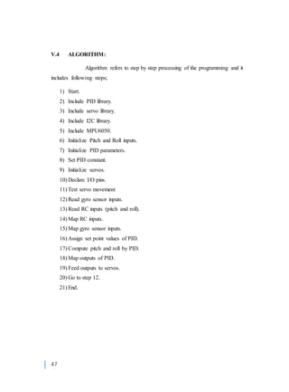
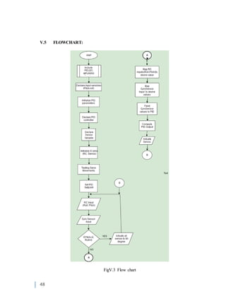
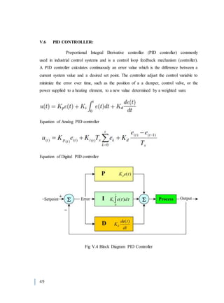
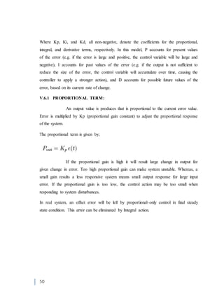
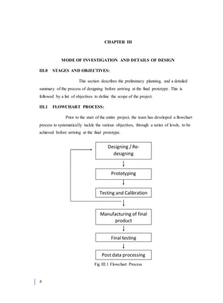
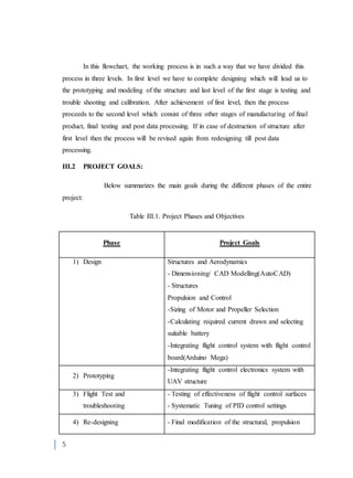
This document describes the design process of a spheroid VTOL UAV. It outlines the objectives, which include designing a strong but lightweight structure within a budget of Rs 50,000. It also describes the flowchart process of designing, prototyping, testing, redesigning, manufacturing the final product, and final testing. The goals are to size the motor and propeller, integrate the flight control electronics, test and tune the flight control surfaces, and verify all objectives are met including withstanding impacts during landing.


![14
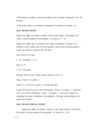
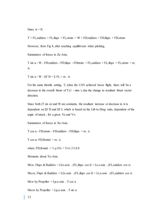
where FL = ½ ρ (Ve + V∞) 2 CL S
(Taking counter-clockwise to be +ve)
Mcg = {[ Lf,z-axis. (FL,flaps cos f) + Lr,z-axis . (FL,rudders cos r) ] + [ Lp,x-axis . T cos
]} - {[ Lf,x-axis. (FL,flaps cos f) + Lr,x-axis . (FL,rudders cos r) ] + [Lp,x-axis . T sinα ]}
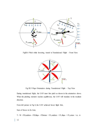
Theoretically, it is difficult to achieve straight and levelled flight during pitching.
However if ΣF L is able to overcome W and ΣF D, it will result in an increase in altitude,
which is more ideal. Therefore, it is concluded that the UAV should flown at a high
enough thrust which must be decreased proportionally to compensate for the increase in
Lift at high velocity to achieve a successful translational flight.
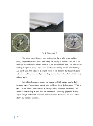
III.7 DESIGN:
In order to make a fair comparison with the Japanese Sphere, some
specifications of the prototypes were based on the limited knowledge of the Japanese
specifications released. A total of 2 prototypes were made, before arriving at the final
prototype and the diameter of the UAV is fixed at 42 centimeters for all three prototypes.
III.7.1 CAD MODELLING:
The prototypes were modelled using Computer Aided Software –
SolidWorks, to speed up the design process by allowing the user to visualize the designs
before manufacturing the actual product. Each parts of the UAV were designed
individually and assembled using the software.
Apart from designing the prototypes to meet the technical specifications, the design
considerations also encompass the manufacturing process. A step-by-step assembly
procedure must be taken into consideration to ensure smooth assembly as some of the
steps require permanent adhesion which is irreversible.](https://image.slidesharecdn.com/8cfce33d-f975-4d63-a87f-459502f74cc8-160215165229/85/SPHEROID-VTOL-UAV-FINAL-THESIS-1-24-320.jpg)