Download to read offline

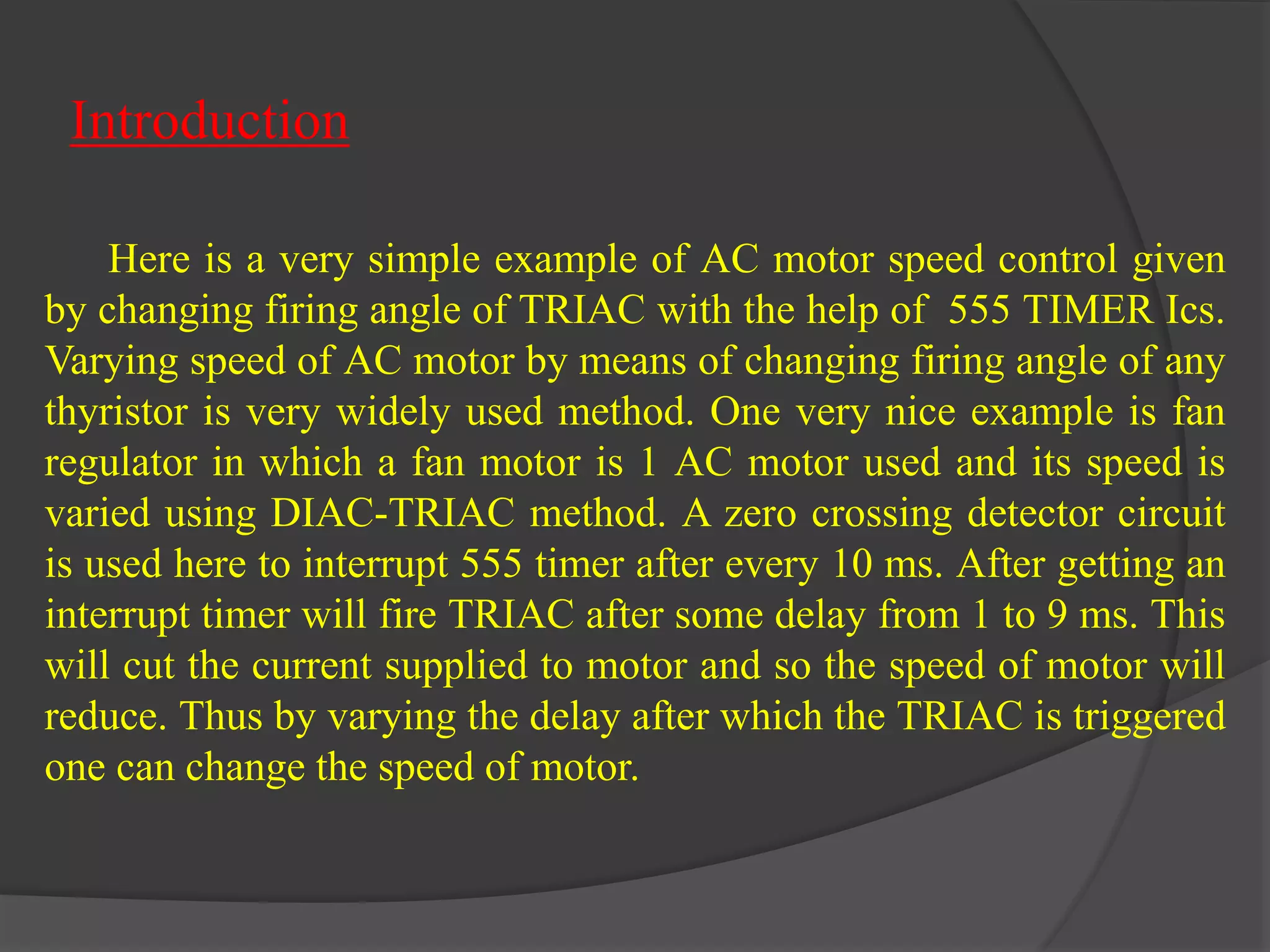


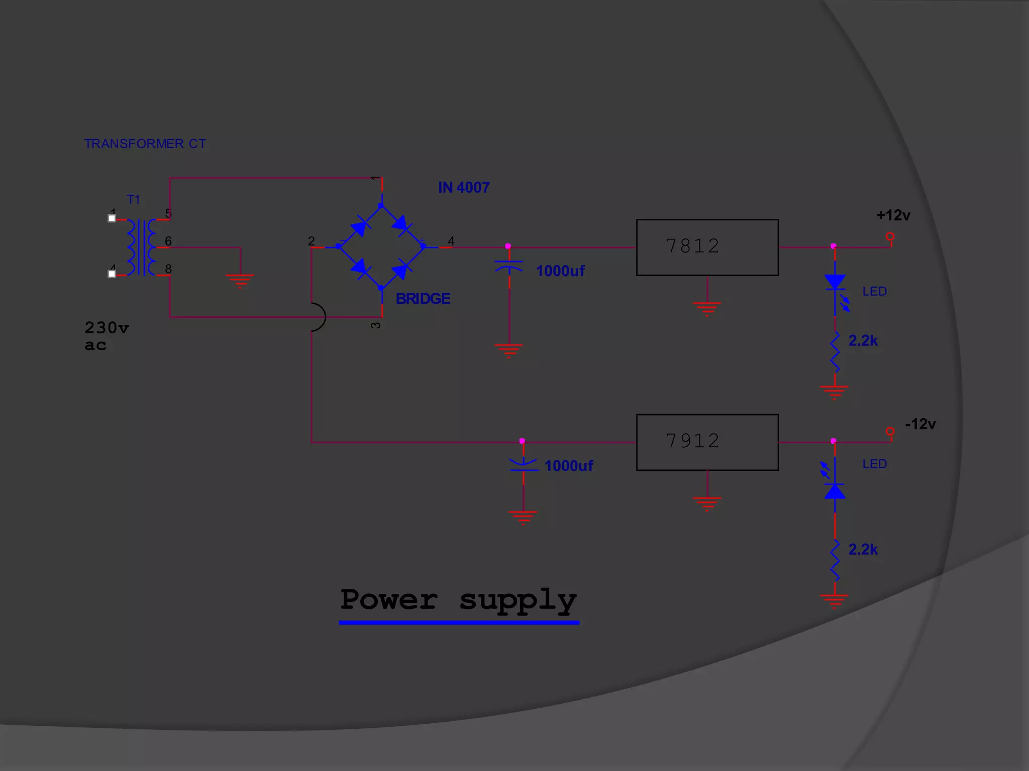


This document discusses the design of a closed-loop speed controller for a single-phase AC induction motor using pulse-width modulation (PWM) of the TRIAC firing angle. It describes how varying the TRIAC firing delay can control motor speed, and how adding a tacho generator and error amplifier in a closed control loop enables set-point speed regulation. Key components include the zero-crossing detector, PWM generator, TRIAC driver, power supply, and control loop circuitry around the motor and tacho generator.