Downloaded 594 times
![Chapter 9
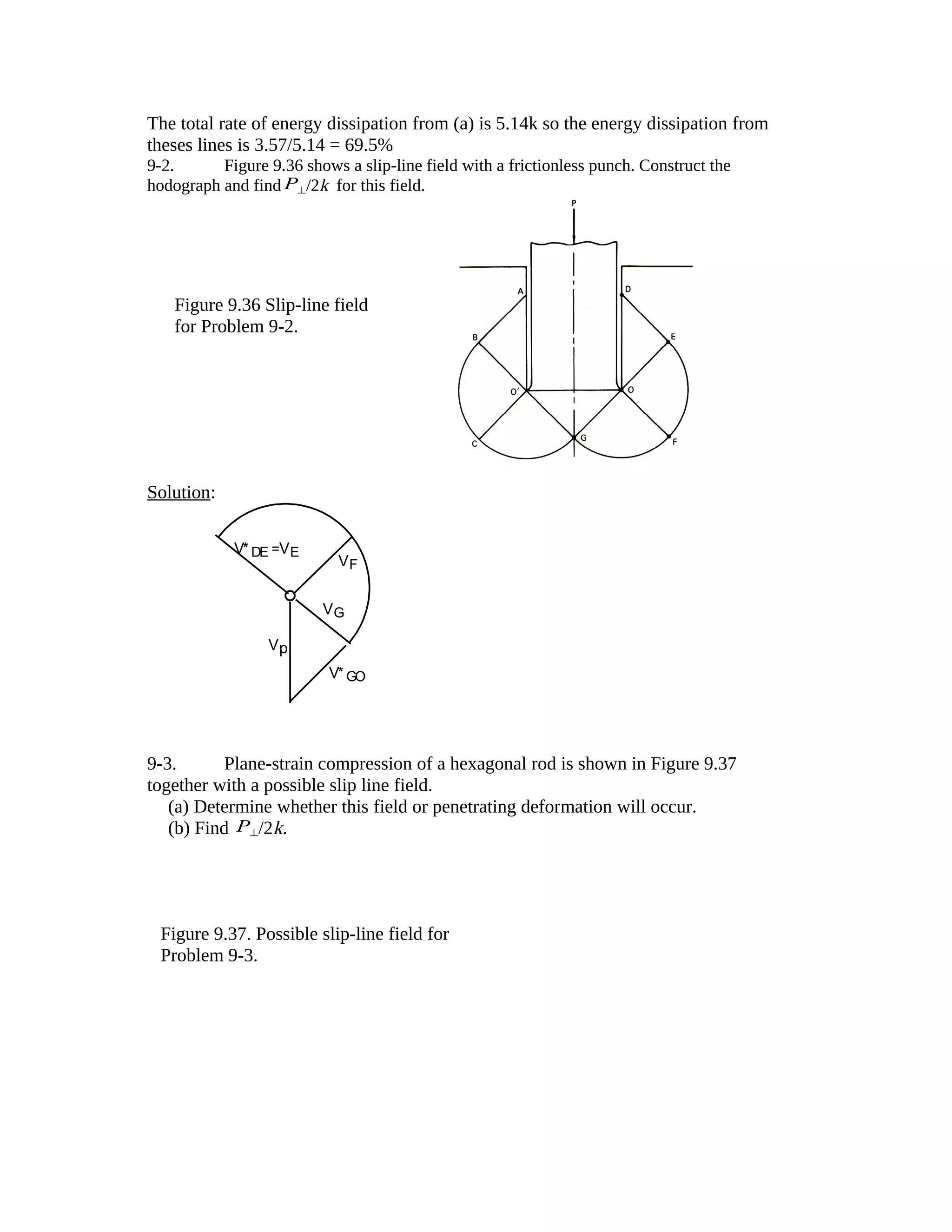
9-1 Using the slip-line field in Figure 9.8 for frictionless indentation it was found that
P⊥/2k = 2.57. Figure 9.35 shows an alternate field for the same problem proposed by Hill.
(a) Find P⊥/2k for this field.
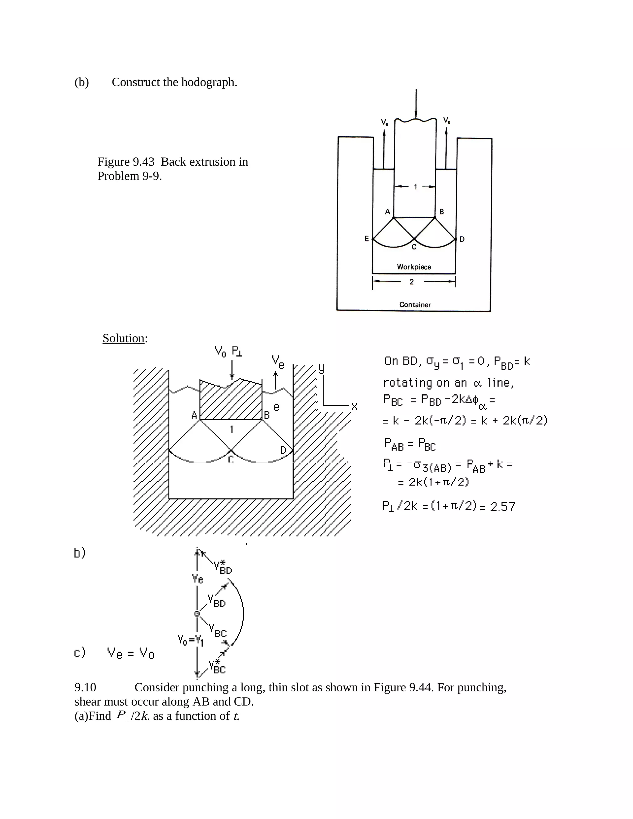
(b) Construct the hodograph.
(c) What percent of the energy is expended along
lines of intense shear?
Figure 9.35 Slip-line field for plane-strain indentation.
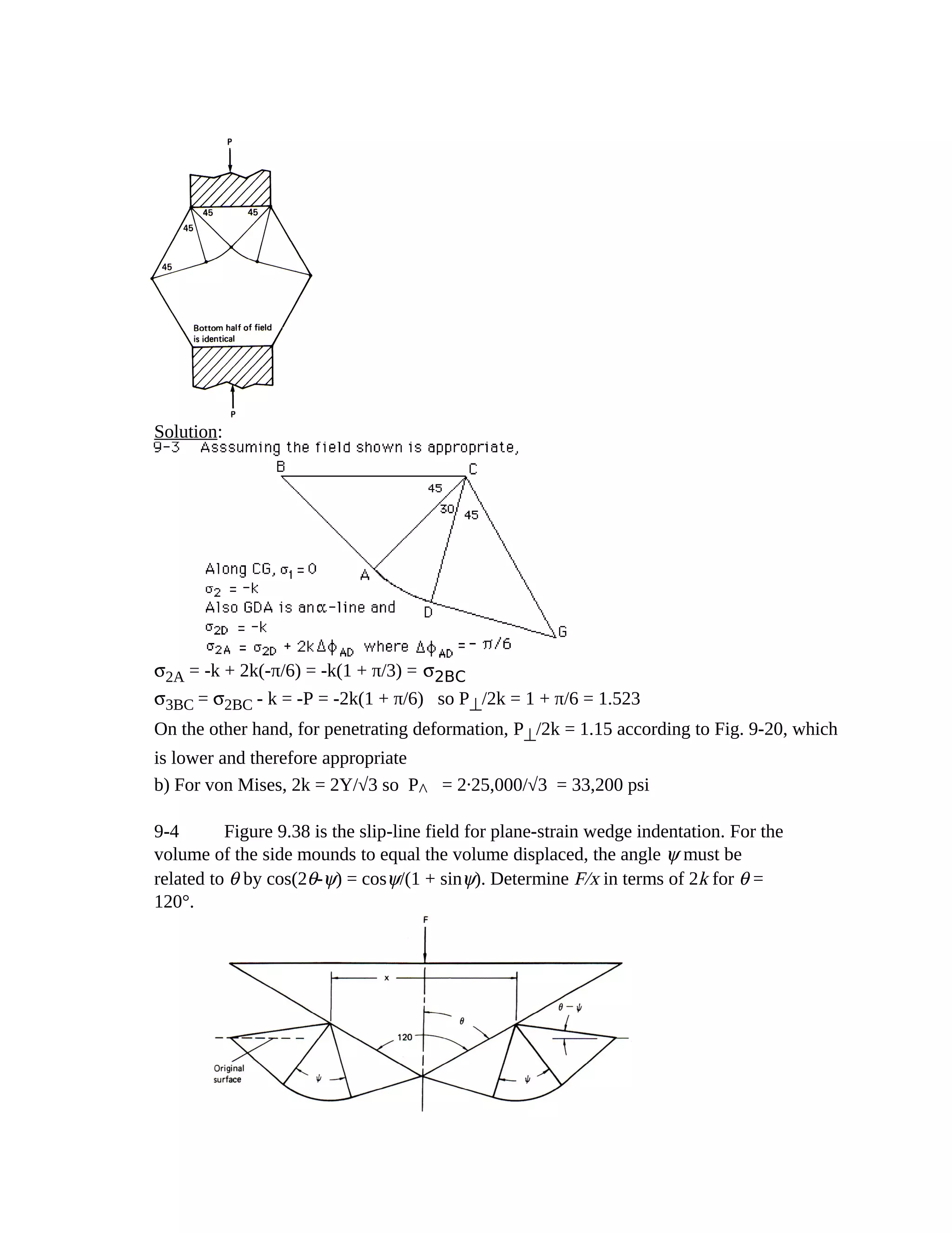
Solution: a)Along ED, σ1 = 0, σ2 = -k, Along EC σ2 = -k, DCFBA is an α-line so in
triangle ABE σ2 = -k +2k∆φ = -k +2k(-π/2) = -k(1+π). σ3 = σ2 -k = P ⊥ . P ⊥ /2k =
1+π/2 = 2.57.
b)
Vp = 1
VAE
V*AB
VF
V*CD
=1,
Intense shear occurs along ABFCD. Note that along BE and EC, the deformation is
gradual.. Letting AE=1, AB=1/√2= BE=CD, BC=(π/2)BE, V*AB = Vp√2 =
V*BC = V*CD so the rate of energy dissipation on these lines is
k( ABV*AB + BCV*BC + CDV*CD) or k[(1/√2)(√2) + π((1/√2)(√2) +(1/√2)
(√2)]Vp. = (2 + π/2)k = 3.57k.](https://image.slidesharecdn.com/solutionmanual9-150303094027-conversion-gate01/75/Solution-manual-9-1-2048.jpg)
![d) rate of energy expenditure along AD and CD = k( ADV*AD+ CDV*CD) = 2k AD
V*AD = 2k(√√2)(√2/2)] = 2k
rate of energy expenditure along arc ABC = k ABCV*ABC
arc length ABC= √2π/2), the velocity discontinuity along this arc V*ABC = V*AD = (√2/2)Vo
= √2/2, so rate of energy = kπ/2 =2k(π/4)
total rate of work = PextVox1 = 2k(1+π/2)
Thefraction expended on lines AD, CD & arc ABC = (1+π/4)/(1+π/2)= 69.4%
The rest is expended in fan = (π/4)/(1+π/2) = 30.6%
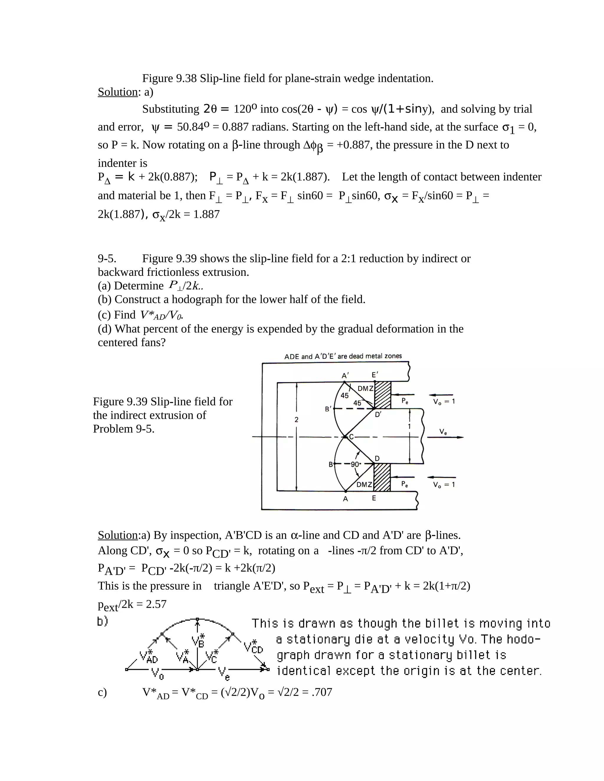
9-6 Fig. 9.40 shows the slip-line field for the 3:1 frictionless extrusion. Find P⊥
/2k and η.
Solution:
This is one of the special fields covered in sect 9-6 for which sinα = r/[2(1-r)]. (Here α =
90o=π/2 so sinα = 1 and r = 2/3. For these fields Pext/(2k) = r(1+α) = (2/3)(1+ π/2) = 1.714
η = wi/wa = 2kε/Pext = 2kε/[2kr(1+α)] = ln3/[(2/3)(1+ π/2)] = η = 64.1%
Note this problem can also be solved by realizing that along PCD = k, and rotating on an α-line
through ∆φα = -π/2, PABD = k + 2k(π/2)
P⊥ = PABD + k = 2k(1+π/2), 3Pext = 2P^, so Pext/2k = (2/3)(1+π/2) etc.
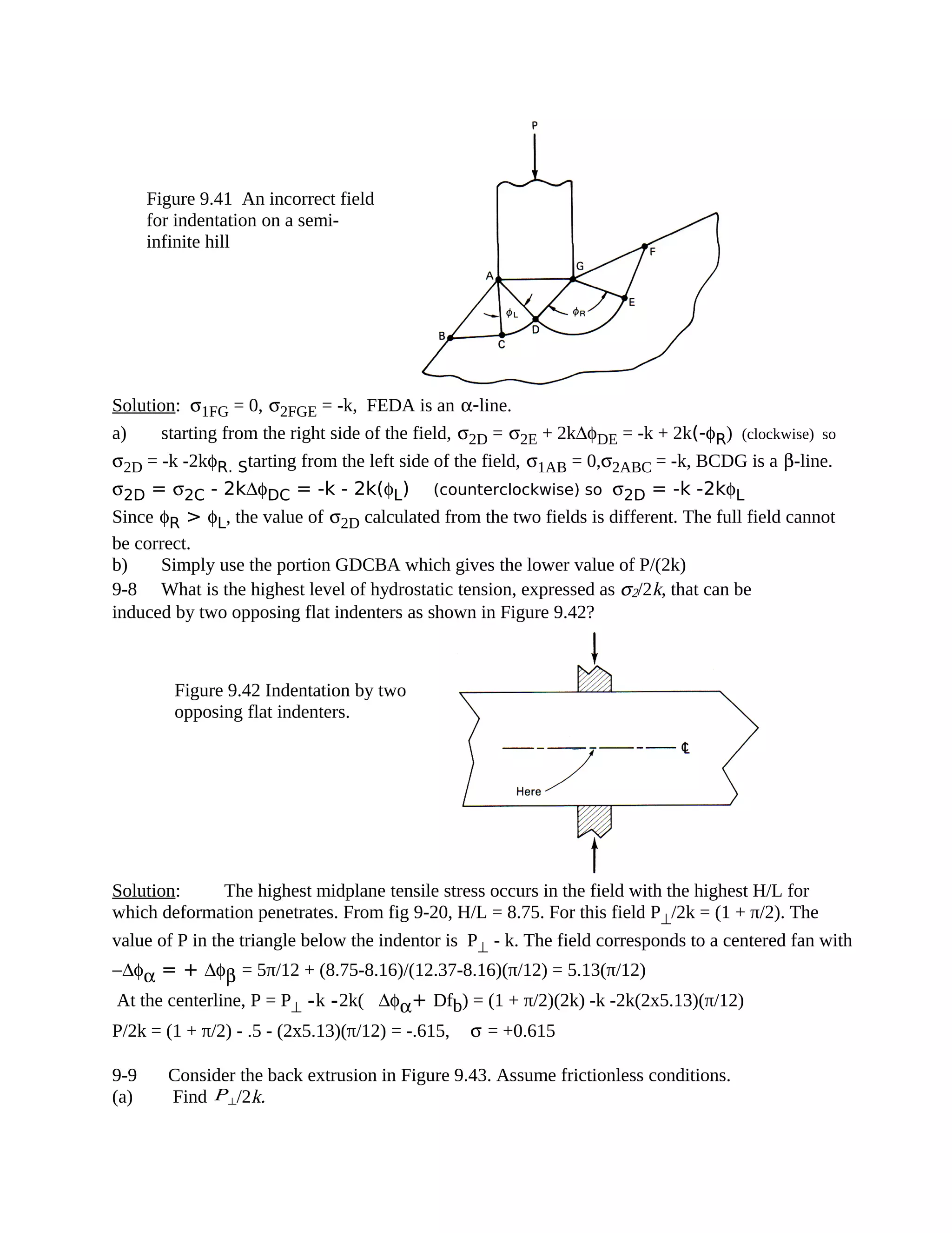
9-7 Indentation of a step on a semi-infinite hill is shown in Figure 9.41. Show that this
field is not possible and draw a correct field
Figure 9.40 The slip-line
field for the 3:1 frictionless
extrusion in Problem 9-6.](https://image.slidesharecdn.com/solutionmanual9-150303094027-conversion-gate01/75/Solution-manual-9-5-2048.jpg)
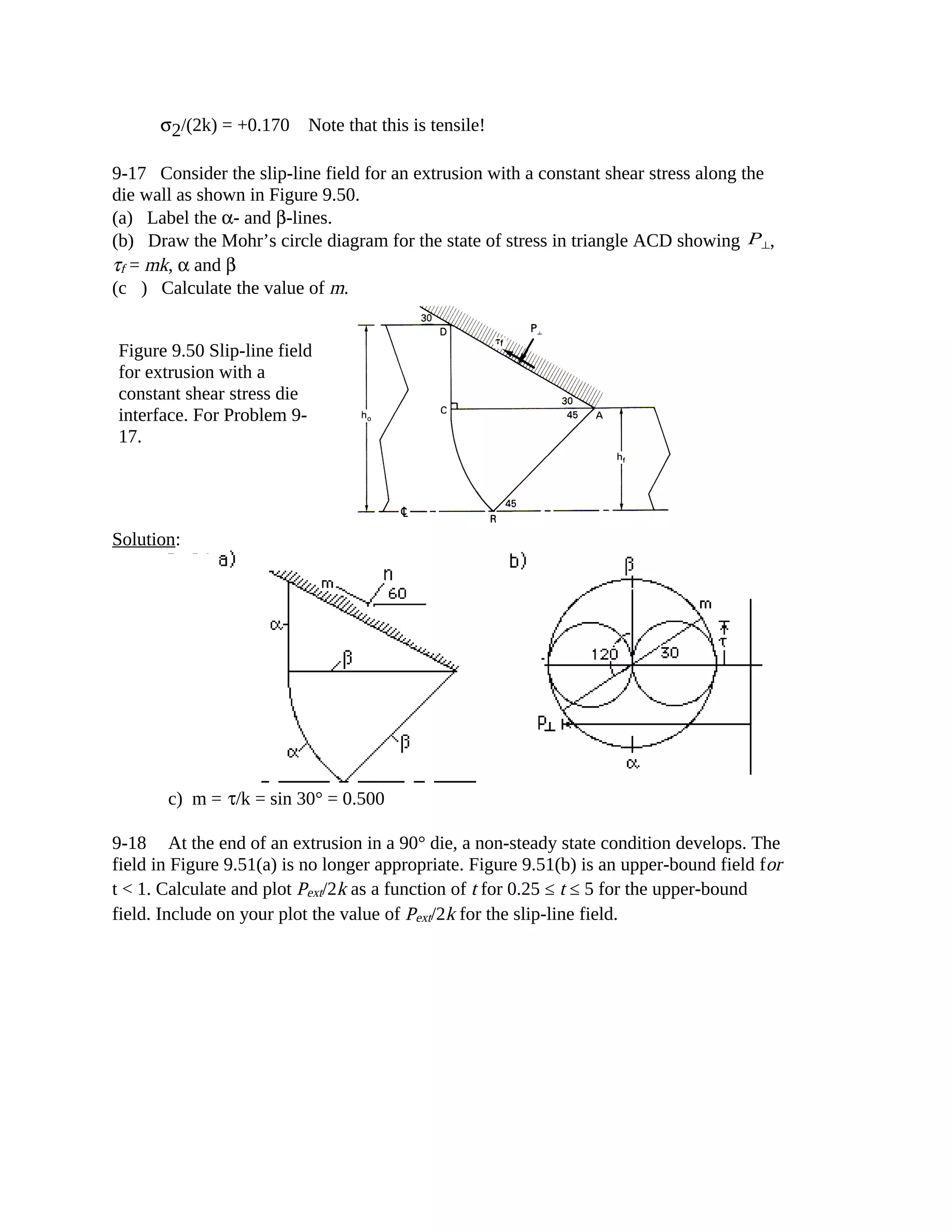
![Solution: From problem 9-12, the value of σx necessary to operate the field is 1.785, or σx = =
1.785(2k) = 3.571k.
Alternatively, shear could occur on a 45o plane from the base of the notch to the opposite surface. The
shear stress on such a plane,
τ = Fxcos45/{(1/cos45)(tn +to)/2} = (1/2)σxtn /[(tn +to)/2] = σxtn /(tn + to).
Shear will occur on such a plane when τ = k, so for shear
k = σxtn/(tn + to) or σx = k(tn + to)/tn = k(1+ to/tn)
For the field to operate instead of shear, 3.571k < k(1+ to/tn), or to/tn > 2.571
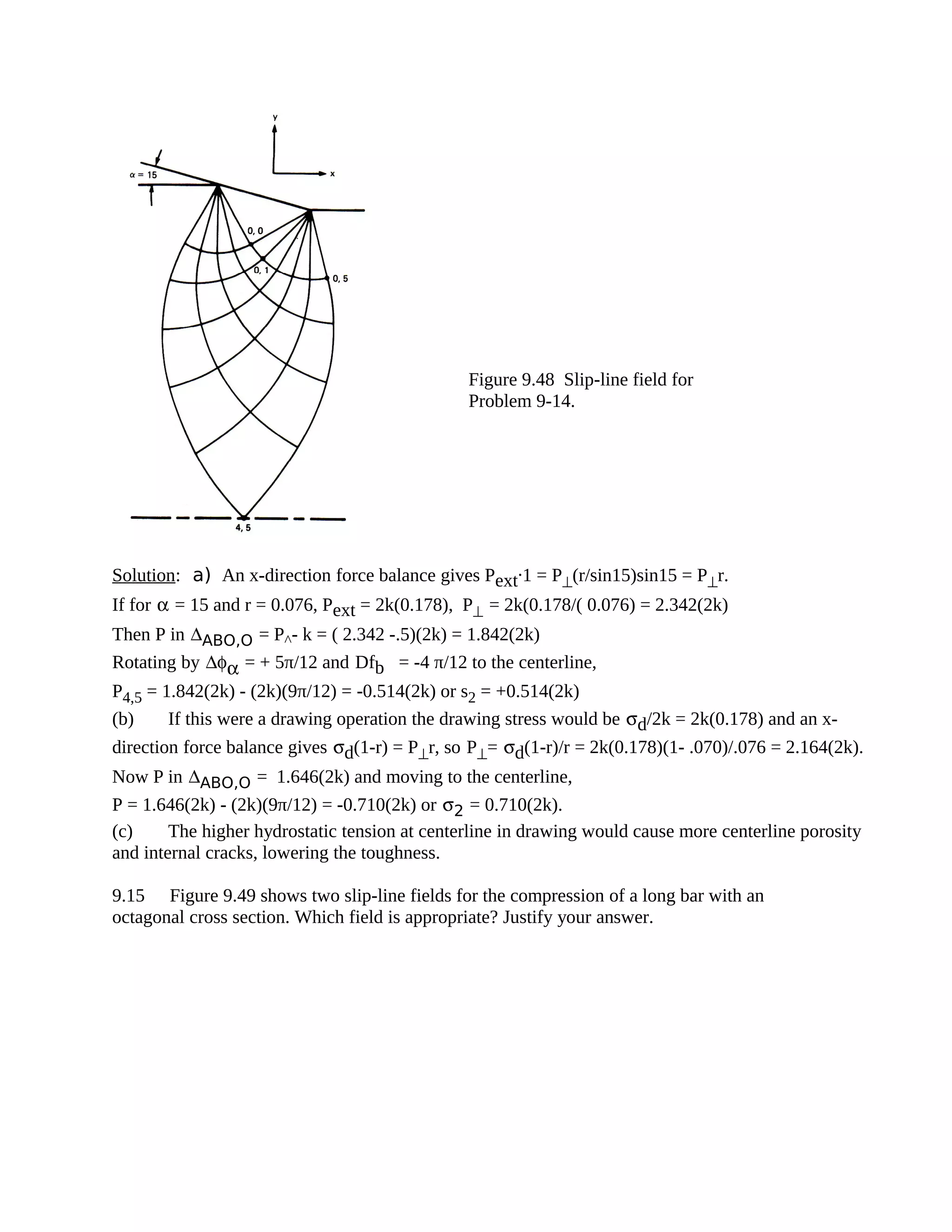
9-14 Figure 9.48 shows the appropriate slip-line field for either frictionless plane-
strain drawing or extrusion where r = 0.0760 and α = 15°.
a. Find the level of σ2 at point 4,5 for extrusion.
b. Find the level of σ2 at point 4,5 for drawing.
c. How might the product depend on whether this is an extrusion or a drawing?
Figure 9.47 Alternate mode of
failure for a notched tensile bar
if to/tn isn’t large enough. For
Problem 9-13.](https://image.slidesharecdn.com/solutionmanual9-150303094027-conversion-gate01/75/Solution-manual-9-10-2048.jpg)
![A 1.0 0.0 0.0
0,2 0.638 1.366 1.00
1,3 0.904 2.12 1.788
2,4 1.335 3.195 2.935
a) hf = 2.935, ho = hf +2sin30 = 3.935
The reduction , r = (ho -hf)/ho = 0.254 or 25.4%
b) A force balance on the die walls is
PAB = P0,0 = -σ3(0,0) and σ3(0,0) = σ2(0,0) - k
so at point 0,0, σ2 = σ3 + k = -3.935Pe + k
σ2(0,2) = σ2(0,0) +2k∆φα = -3.935Pe + k + 2kπ/6 (∆φα = +π/6)
Now rotating from 0,2 to 0,3 by ∆φα = +π/12 and then from 0,3 to 1,3 by ∆φβ = -π/12σ2(0,2)
= σ2(0,0) +2k∆φα = -3.935Pe + k + 2kπ/6
σ2(1,3) = σ2(0,2) +2k(π/12) - 2k(-π/12) = -3.935Pe + k[1+(2/3)π]Now rotating from 1,3 to 1,4
by ∆φα +π/12 and then from 1,4 to 2,4 by ∆φβ = -π/12σ2(2,4) = σ2(1,3) +2k(π/12) - 2k(-π/12)
= -3.935Pe + k([1+π)
Everywhere along the cut σx = σ1 = σ2 + k
from A to 0,2 (y from 0 to 1), σ1 = -3.935Pe + 2k(1 + π/63)at 1,3 (y = 1.788), σ1 = -3.935Pe + 2k(1 +
π/3) at 2,4 (y = 2.935), σ1 = -3.935Pe + 2k(1 + π/2)
Noting that for all these points, σx = -3.935Pe + 2k + f(y), Fx = 0 = ∫σxdy may be expressed as Fx =
0 = (-3.935Pe + 2k)(2.935) +∫f(y)dy. Now plotting f(y) vs. y:
It can be seen that ∫f(y)dy = 1.πk/3 + (1.5πk/3)(1.788 -1.00) + (2.5πk/3)(2.935 -1.788) = 5.29k
Fx = 0 = -3.935Pe(2.935) + 2k(2.935) + 5.29kPe/(2k) = 0.483
c) η = wi/wa where wi = 2kεh = 2k(ln[1/(1-r)] = 0.293 and wa = Pe
η = 0.293/0.483 = 60.7%
d) at point 2,4, σ2 = -3.935Pe + (1+π)k = -3.935(.483.2k) + (1+π)k](https://image.slidesharecdn.com/solutionmanual9-150303094027-conversion-gate01/75/Solution-manual-9-13-2048.jpg)
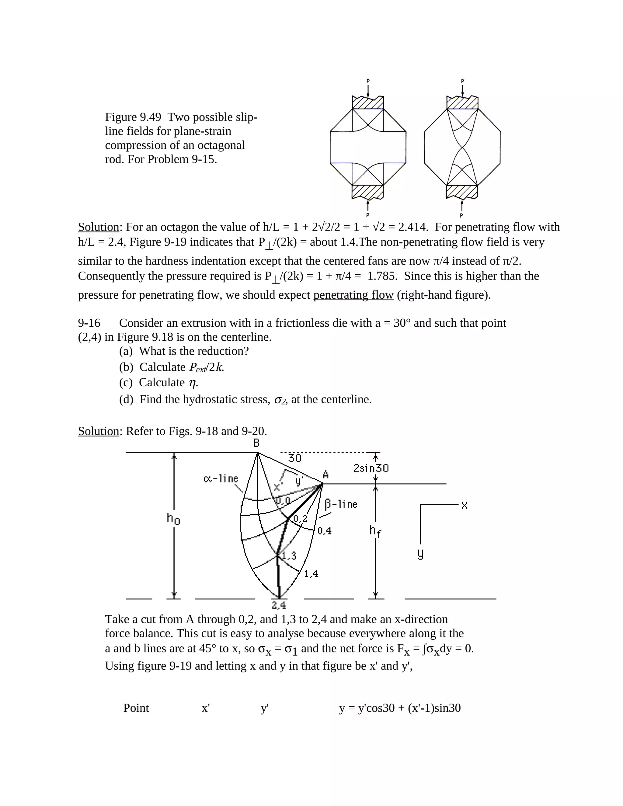
![Solution:
For the slip-line field (a): Along CD σ1 = 0, σ2 = k, and CBA is an α-line
σ2A = σ2ACD = σ2C + 2k∆φAC where ∆φAC = -π/2, σ2ACD = -k + 2k(-π/2) = -k(1 +
π)σ3AD = σ2ACD - k = -2k(1 + π/2) = - P⊥. P⊥ = 2k(1 + π/2); Making a force balance, P⊥
.1 =
2Pe so Pe = k(1 + π/2). Pe/(2k) = (1 + π/2)/2 = 1.285
For the upper-bound field, r = 50%, Ve = 2Vo and γ = θ
2PeVo = k( AOV*AO + OCV*OC) = k(2(t/cosθ)(Vo/cosθ),
Substituting cosθ= t/ AOand AO2 = t2 +1
2PeVo = 2kVo[t(t2+1)/t2] = 2kVo(t + 1/t), Pe/(2k) = (t + 1/t)/2
t Pe/(2k) t Pe/(2k) t Pe/( AO2k)
.25 2.125 .75 1.04 2 1.25
.375 1.52 1.0 1.0 3 1.67
.5 1.25 1.25 1.025 4 2.125
.625 1.11 1.5 1.08 5 2.6
Figure 9.51 (a) Slip-line field for a 2:1
extrusion. (b) Upper-bound field for
the end of a 2:1 extrusion. For Problem
9-18.](https://image.slidesharecdn.com/solutionmanual9-150303094027-conversion-gate01/75/Solution-manual-9-15-2048.jpg)
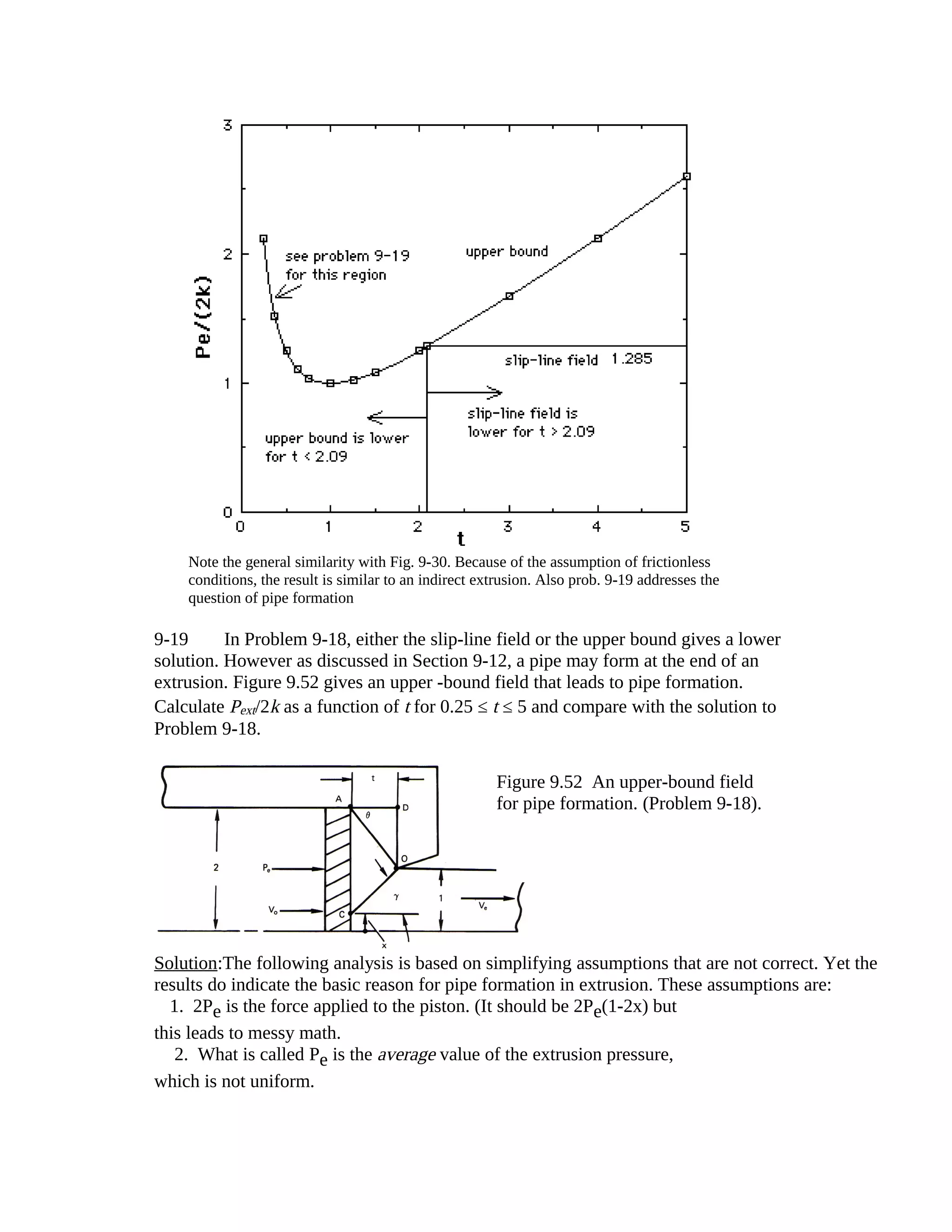
![As point C moves upward along the piston face, x increases, and the metal adjacent to the piston
face moves faster than Vo so a pipe forms. A general hodograph is shown:
Now Ve depends on x, Ve(1-x) = Vo(2-x) or Ve = (2-x)/(1-x)Now to find the value of x for a
minimum Pe.
2VoPe = k[ AOV*AO + OCV*CO]; V*AO = Vo/cosθ and V*CO = (Ve -Vo)/cosγ,
AO= t/cosθ, OC= t/cosγ Now, V*CO = [(2-x)/(1-x) -1]/cosγ = 1/[(1-x) cosγ]
2VoPe = k{(t2+1)/t + [t2 + (1-x)2]/[t(1-x)]} (a)
Setting dPe/dx = 0 to find the minimum, t/(1-x2) -1/t = 0 or t = 1-x, so when γ = 45°, Pe is a
minimum. Substituting t = 1-x into (a),
Pe/(2k) = (1/4)[1-x + 1/(1-x) + 1 +1] = (1/4)[3 - x + 1/(1-x)]. Pe/(2k) = (1/4)[2+t+1/t]
(note this solution is valid only for t ≤ 1 (γ ≤ 45 an x ≥ 0. For t ≤ 1 the solution of Prob.
9-18 gives a lower value than the slip-line field solution)
t Pe/(2k) t Pe/(2k)
.25 1.56 .625 1.056
.375 1.26 .75 1.02
.50 1.13 1.00 1.00](https://image.slidesharecdn.com/solutionmanual9-150303094027-conversion-gate01/75/Solution-manual-9-17-2048.jpg)

This document contains solutions to multiple problems involving slip-line field analysis. Problem 9-14 asks about a slip-line field for extrusion or drawing where r=0.0760 and α=15°. For extrusion, the stress σ2 at point 4,5 is found to be 1.842(2k). For drawing, σ2 would have the same magnitude but opposite sign. The product may depend on whether it is an extrusion or drawing, as extrusion would result in a thicker product while drawing a thinner product.