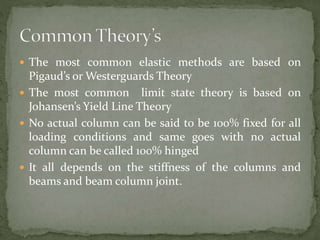
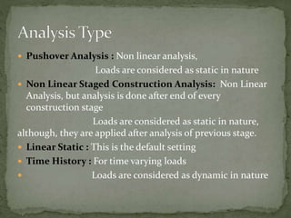
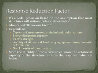
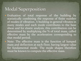
By Rishabh Lala
X Semester
Rajiv Gandhi Proudyogiki Vishwavidyalaya
Integrated PG Program
Civil and Structural Engineering
 Accounts for Shear
Behavior
 Important when thickness
is greater than one tenth
of the span
 Recommended for more
accurate analysis
 Should not be used when
shear deformation is
known to be small.
 Neglects transverse shear
deformation
 When deformation is pure
bending, thin shell should
be used
 Pushover Analysis : Non linear analysis,
Loads are considered as static in nature
 Non Linear Staged Construction Analysis: Non Linear
Analysis, but analysis is done after end of every
construction stage
Loads are considered as static in nature,
although, they are applied after analysis of previous stage.
 Linear Static : This is the default setting
 Time History : For time varying loads
 Loads are considered as dynamic in nature
 Two Types :
 A. Material Non Linearity: Time Dependent
Example : Concrete, Frame Hinges
 Geometric Non Linearity : P Delta Non Linearity
P Delta With large Displacements
 Considering slabs as diaphragms is part of the
approximate analysis
 Diaphragms distribute horizontal forces to the vertical
elements
 Rigid diaphragms are assumed to have infinite inplane
stiffness
 Seismic loading are applied at the center of mass
 Used for faster analysis
 Simulate actual inplane stiffness
 Building codes favour this
 Used when there are chances of significant inplane
deformation
 Example: Slabs with openings, L- or C-shaped
buildings where the ends of the wings can drift
independently of each other.
 Accidental eccentricity is applied at every node
 It is often appropriate to analyze, some stories with
rigid and some with semi-rigid diaphragm asumption
 Centroid of the stiffness, within the floor diaphragm
 Its position is independent of loading magnitude
 Its position is different for different storeys
 If lateral loads are applied to the rigid diaphragm, then
its position is the one, which does not causes any
rotation in that storey.
 Equilibrium equations takes into account, the partially
deformed shape of the structure also.
 Note: Tensile forces tend to resist rotation and
compressive forces tend to enhance rotation and
destabilize the structure, whereas tensile forces stiffen
the structure. This requires moderate iterations.
 ‘P Delta for large scale displacements’ can be used in
case of cables undergoing large displacements. This
may require, large amount of iterations to model large
displacements and large rotations.
 Related to inelastic behaviour of material of the
structural component, characterized by force-
displacement (F-D) relationship.
 Static non Linear analysis method, where structure is
subjected to gravity loading
 Results provide insight into ductile capacity of the
structural system and indicate the mechanism, load
level and deflection at which failure occurs
 When analysis frame objects, material non linearity is
assigned to discrete hinge locatinos, where plastic
rotation occurs
 A yield zone with specific inelastic rotation, which
forms in a member when plastic moment is reached in
a section.
 Plastic Moment: When entire cross-section has
yielded to bending moment, the moment carrying
capacity at that time is called plastic moment.
 Plastic Section: Moment carrying capacity of the cross-
section
 At any cross-section, the plane before bending, remains
plane after bending
 All tensile stresses are taken up by reinforcement and not
by concrete
 Tensile stresses may be calculated by F1/(Ac + M.Ast)
Where :
F1 = Total tension in the member, i.e. pretension in steel
before concreting
Ac = Cross – section of concrete excluding any finish and
excluding steel
M = Modular Ratio
Ast = Area of cross section of reinforcing steel in tension
 Q = ∑ Pu Du /u(Hu.hs)
 Where:
 ∑ Pu = Sum of axial loads on all columns in the story
 Du = elastically computed first order lateral deflection
 Hu = total lateral force acting within the story
 hs = height of story
 If Q <= 0.04  no sway columns
 If Q >= 0.004  sway columns

 The most common elastic methods are based on
Pigaud’s or Westerguards Theory
 The most common limit state theory is based on
Johansen’s Yield Line Theory
 No actual column can be said to be 100% fixed for all
loading conditions and same goes with no actual
column can be called 100% hinged
 It all depends on the stiffness of the columns and
beams and beam column joint.
 It’s a codal provision based on the assumption that most
structures will sustain inelastic deformation.
 Also, called “Behaviour Factor”.
 Depends on :
 Capacity of structure to sustain inelastic deformations
 Energy dissipation capacity
 Its over strength
 Stability of its vertical load carrying system during inelastic
deformation
 Non Linearity of the structure
 More the ductility of the structure i.e. more the rotational
capacity of the structure, more is the response reduction
factor
 This coefficient is based on the spectral response
acceleration.
 This allows us to design buildings for about 20% of the
earthquake forces, by utilizing the flexibility of the
structure provided by its ductility. Response reduction
factor theory gains its relevance, as most of today’s
designs are based on the Earthquake Design
Philosophy.
 Elastic : Instant Recovery
 Inelastic : Very Slow Recovery and might not be 100%
 Plastic : No Recovery

 Evaluation of total response of the building by
statistically combining the response of finite number
of modes of vibration. A building in general vibrates in
many modes and each mode contributes to the base
shear and for elastic analysis, this contribution can be
determined by multiplying the % of total mass, called
effective mass by the acceleration corresponding to
that modal period.
 Note: The effective mass is the function of lumped
mass and deflection at each floor, having largest value
for fundamental mode. The mode shapes therefore
must be known to compute the effective mass.
 Modal Analysis is a general procedure for linear
analysis of the dynamic response of the structure.
Modal Analysis has been widely used in the
earthquake resistant design of special structures, such
as very tall buildings, dams, etcetera.
 However, it has become common for ordinary
structures as well, as cost of the high speed computing
due to the availability of the not so costly analysis
software has come down.
 Modeling of tall structures to an extent is dependent on the type
of analysis done.
 The usual approach is to conduct approximate analysis in the
preliminary stage and then accurate analysis in the final stage.
 Some of the approximations usually done are:
 1. Numerous hinges are inserted at points of assumed points of
contraflexure in the beams and columns of a rigid frame to
convert the structure into a statically determinate one, from an
indeterminate structure.
 2.Approximating simple cantiliver instead of a complex bent.
 3.If structure is symmetrical, half model analysis is also
acceptable
 Slabs can be assumed to be diaphragms
 Material: Linearly Elastic : This assumption allows for
linear methods of analysis
 Participating Components : Only primary components
participate in overall behavior, ignoring the secondary
structural and non-structural components like brick in-
fills, heavy cladding, which may have significant effect on
the stiffness of the structure.
 Floor Slab : Assumed to be rigid in plane. This assumption
may fail during narrow and long slab, precast slabs,
etcetera.
 Cracking : Effects of cracking due to flexural stress are
assumed to be represented by reduced moment of inertia
of beams by 50% and columns by 80% of the uncracked
values.

Software analysis concepts

  • 1.
    By Rishabh Lala XSemester Rajiv Gandhi Proudyogiki Vishwavidyalaya Integrated PG Program Civil and Structural Engineering
  • 2.
     Accounts forShear Behavior  Important when thickness is greater than one tenth of the span  Recommended for more accurate analysis  Should not be used when shear deformation is known to be small.  Neglects transverse shear deformation  When deformation is pure bending, thin shell should be used
  • 3.
     Pushover Analysis: Non linear analysis, Loads are considered as static in nature  Non Linear Staged Construction Analysis: Non Linear Analysis, but analysis is done after end of every construction stage Loads are considered as static in nature, although, they are applied after analysis of previous stage.  Linear Static : This is the default setting  Time History : For time varying loads  Loads are considered as dynamic in nature
  • 4.
     Two Types:  A. Material Non Linearity: Time Dependent Example : Concrete, Frame Hinges  Geometric Non Linearity : P Delta Non Linearity P Delta With large Displacements
  • 5.
     Considering slabsas diaphragms is part of the approximate analysis  Diaphragms distribute horizontal forces to the vertical elements  Rigid diaphragms are assumed to have infinite inplane stiffness  Seismic loading are applied at the center of mass  Used for faster analysis
  • 6.
     Simulate actualinplane stiffness  Building codes favour this  Used when there are chances of significant inplane deformation  Example: Slabs with openings, L- or C-shaped buildings where the ends of the wings can drift independently of each other.  Accidental eccentricity is applied at every node  It is often appropriate to analyze, some stories with rigid and some with semi-rigid diaphragm asumption
  • 7.
     Centroid ofthe stiffness, within the floor diaphragm  Its position is independent of loading magnitude  Its position is different for different storeys  If lateral loads are applied to the rigid diaphragm, then its position is the one, which does not causes any rotation in that storey.
  • 8.
     Equilibrium equationstakes into account, the partially deformed shape of the structure also.  Note: Tensile forces tend to resist rotation and compressive forces tend to enhance rotation and destabilize the structure, whereas tensile forces stiffen the structure. This requires moderate iterations.  ‘P Delta for large scale displacements’ can be used in case of cables undergoing large displacements. This may require, large amount of iterations to model large displacements and large rotations.
  • 9.
     Related toinelastic behaviour of material of the structural component, characterized by force- displacement (F-D) relationship.
  • 10.
     Static nonLinear analysis method, where structure is subjected to gravity loading  Results provide insight into ductile capacity of the structural system and indicate the mechanism, load level and deflection at which failure occurs  When analysis frame objects, material non linearity is assigned to discrete hinge locatinos, where plastic rotation occurs
  • 11.
     A yieldzone with specific inelastic rotation, which forms in a member when plastic moment is reached in a section.  Plastic Moment: When entire cross-section has yielded to bending moment, the moment carrying capacity at that time is called plastic moment.  Plastic Section: Moment carrying capacity of the cross- section
  • 12.
     At anycross-section, the plane before bending, remains plane after bending  All tensile stresses are taken up by reinforcement and not by concrete  Tensile stresses may be calculated by F1/(Ac + M.Ast) Where : F1 = Total tension in the member, i.e. pretension in steel before concreting Ac = Cross – section of concrete excluding any finish and excluding steel M = Modular Ratio Ast = Area of cross section of reinforcing steel in tension
  • 13.
     Q =∑ Pu Du /u(Hu.hs)  Where:  ∑ Pu = Sum of axial loads on all columns in the story  Du = elastically computed first order lateral deflection  Hu = total lateral force acting within the story  hs = height of story  If Q <= 0.04  no sway columns  If Q >= 0.004  sway columns 
  • 14.
     The mostcommon elastic methods are based on Pigaud’s or Westerguards Theory  The most common limit state theory is based on Johansen’s Yield Line Theory  No actual column can be said to be 100% fixed for all loading conditions and same goes with no actual column can be called 100% hinged  It all depends on the stiffness of the columns and beams and beam column joint.
  • 15.
     It’s acodal provision based on the assumption that most structures will sustain inelastic deformation.  Also, called “Behaviour Factor”.  Depends on :  Capacity of structure to sustain inelastic deformations  Energy dissipation capacity  Its over strength  Stability of its vertical load carrying system during inelastic deformation  Non Linearity of the structure  More the ductility of the structure i.e. more the rotational capacity of the structure, more is the response reduction factor
  • 16.
     This coefficientis based on the spectral response acceleration.  This allows us to design buildings for about 20% of the earthquake forces, by utilizing the flexibility of the structure provided by its ductility. Response reduction factor theory gains its relevance, as most of today’s designs are based on the Earthquake Design Philosophy.
  • 17.
     Elastic :Instant Recovery  Inelastic : Very Slow Recovery and might not be 100%  Plastic : No Recovery 
  • 18.
     Evaluation oftotal response of the building by statistically combining the response of finite number of modes of vibration. A building in general vibrates in many modes and each mode contributes to the base shear and for elastic analysis, this contribution can be determined by multiplying the % of total mass, called effective mass by the acceleration corresponding to that modal period.  Note: The effective mass is the function of lumped mass and deflection at each floor, having largest value for fundamental mode. The mode shapes therefore must be known to compute the effective mass.
  • 19.
     Modal Analysisis a general procedure for linear analysis of the dynamic response of the structure. Modal Analysis has been widely used in the earthquake resistant design of special structures, such as very tall buildings, dams, etcetera.  However, it has become common for ordinary structures as well, as cost of the high speed computing due to the availability of the not so costly analysis software has come down.
  • 20.
     Modeling oftall structures to an extent is dependent on the type of analysis done.  The usual approach is to conduct approximate analysis in the preliminary stage and then accurate analysis in the final stage.  Some of the approximations usually done are:  1. Numerous hinges are inserted at points of assumed points of contraflexure in the beams and columns of a rigid frame to convert the structure into a statically determinate one, from an indeterminate structure.  2.Approximating simple cantiliver instead of a complex bent.  3.If structure is symmetrical, half model analysis is also acceptable  Slabs can be assumed to be diaphragms
  • 21.
     Material: LinearlyElastic : This assumption allows for linear methods of analysis  Participating Components : Only primary components participate in overall behavior, ignoring the secondary structural and non-structural components like brick in- fills, heavy cladding, which may have significant effect on the stiffness of the structure.  Floor Slab : Assumed to be rigid in plane. This assumption may fail during narrow and long slab, precast slabs, etcetera.  Cracking : Effects of cracking due to flexural stress are assumed to be represented by reduced moment of inertia of beams by 50% and columns by 80% of the uncracked values.