Flexibility Method
• Theflexibility method, also known as the force method or
compatibility method, is a technique for analyzing statically
indeterminate structures.
• It involves determining the redundant forces by
establishing force-displacement relationships for structural
members and combining them to produce a relationship
for the entire structure.
• This method is suitable when kinematic indeterminacy is
greater than static indeterminacy.
4.
• Determining StaticIndeterminacy: Identify the degree
of static indeterminacy (DSI) of the structure.
• Choosing Redundant Forces: Select the redundant
forces to be analyzed.
• Creating a Basic Determinate Structure: Remove the
redundant restraints, creating a basic determinate
structure.
• Establishing Force-Displacement
Relationships: Determine the displacements caused
by a unit load at each redundant force location.
5.
• Compatibility Equation:Apply compatibility
equations to ensure displacement compatibility at
the redundant force locations.
• Solving for Redundant Forces: Solve the
compatibility equations to find the values of the
redundant forces.
• Calculating Member Forces: Determine member
forces by combining the forces in the basic
determinate structure and those caused by the
redundant forces.
6.
• Flexibility Matrix:
•The flexibility matrix is a square matrix that
represents the displacement at coordinate i
due to a unit force at coordinate j in a
structure.
• It's also known as the "flexibility coefficient".
• The matrix elements are displacements, and
it's always a symmetric matrix.
7.
• Advantages andLimitations:
• Advantages:
• Suitable for structures with a high degree of
static indeterminacy and can provide an
understanding of the structure's behavior.
8.
• Limitations:
• Canbe more computationally intensive for
complex structures compared to stiffness
methods.
•
9.
• Applications:
• Beams,Frames, and Indeterminate structures
with single or double degrees of indeterminacy.
• In essence, the flexibility method provides a
systematic approach to analyzing statically
indeterminate structures by focusing on the
relationship between forces and displacements,
ultimately determining the redundant forces
and internal forces in the structure.
11.
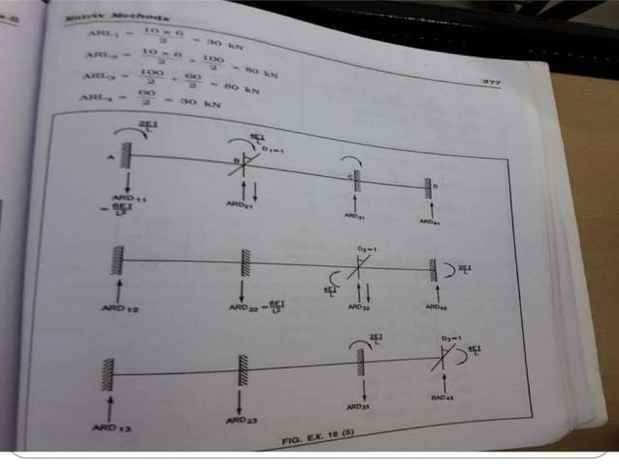
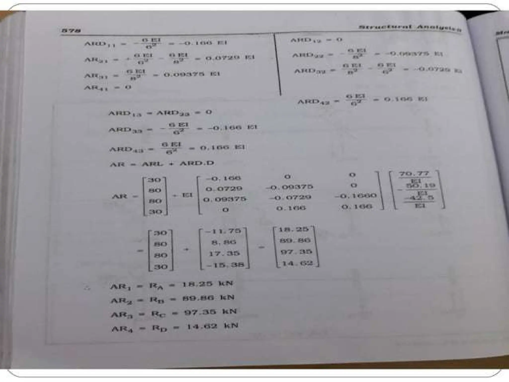
STIFFNESS METHOD
• Elementand global stiffness matrices –
Analysis of continuous beams – Co-ordinate
transformations – Rotation matrix –
Transformations of stiffness matrices, load
vectors and displacements vectors – Analysis
of pin-jointed plane frames and rigid frames
(with redundancy limited to two).
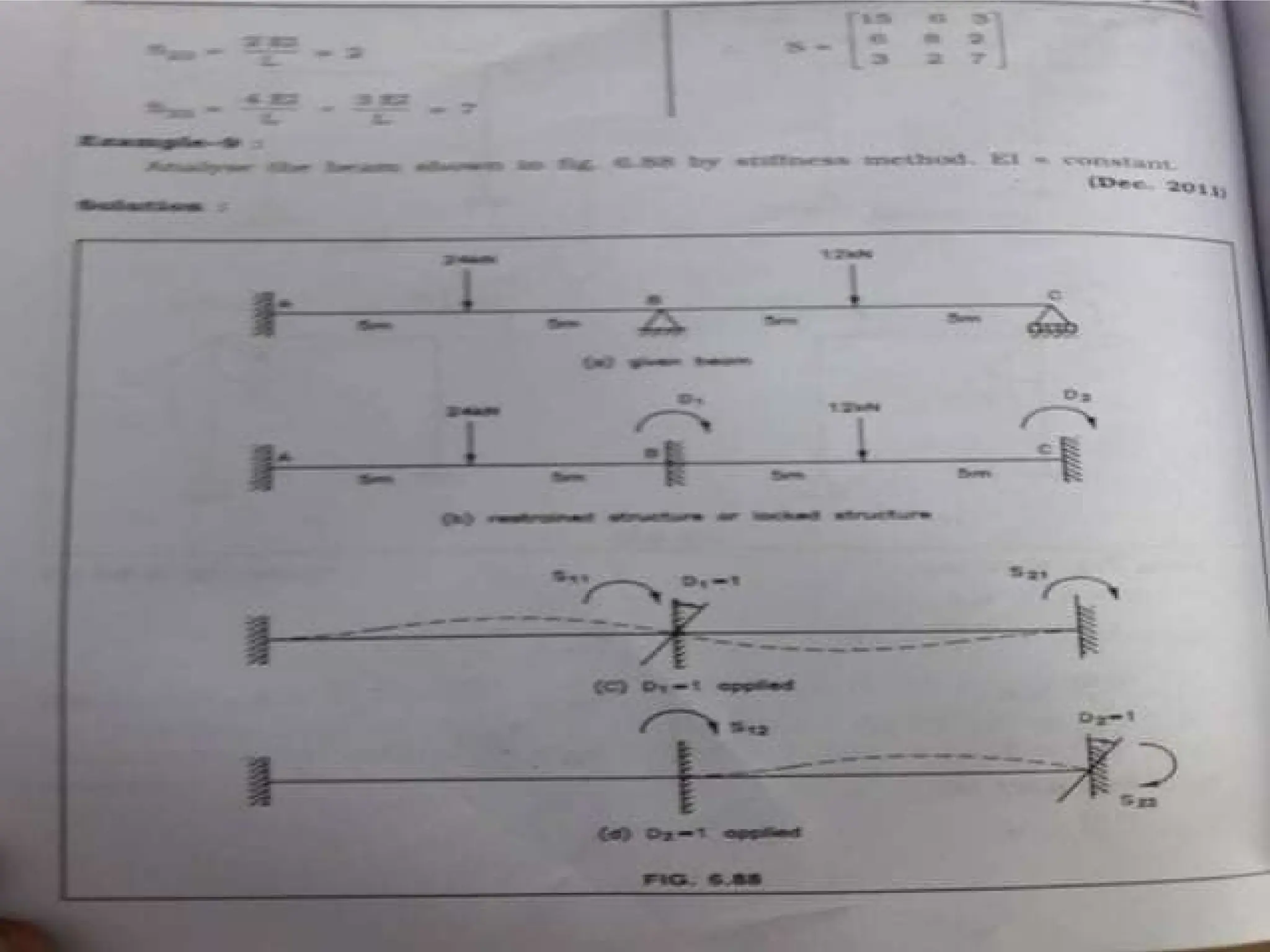
12.
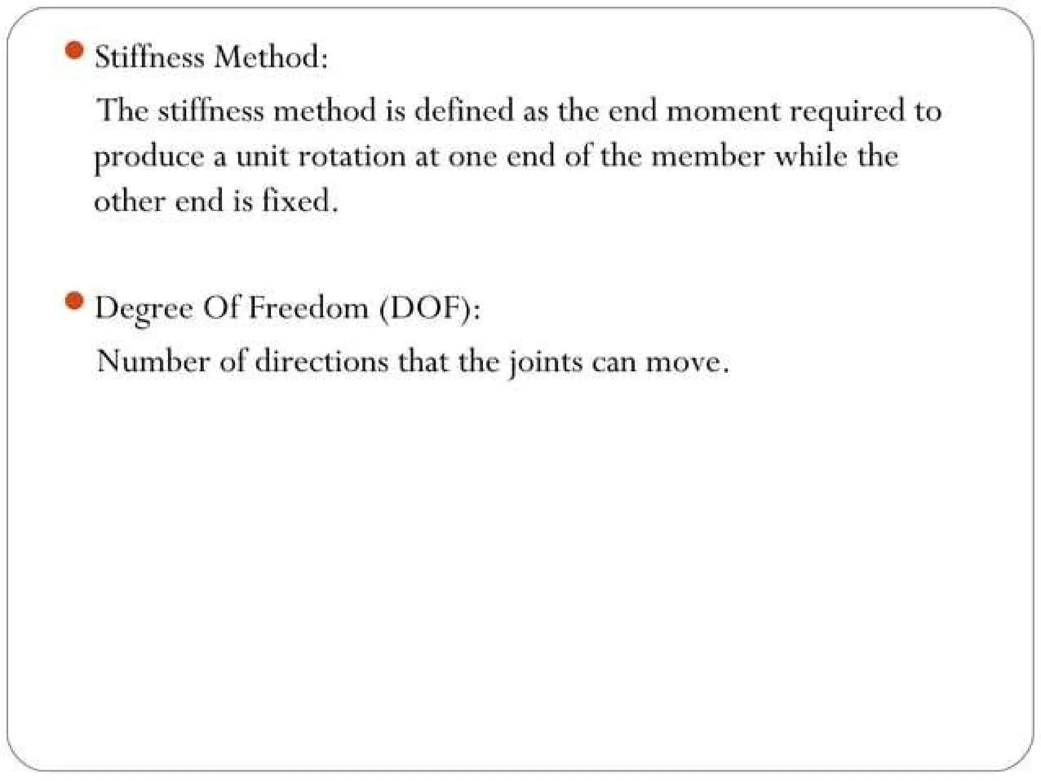
• The stiffnessmethod, also known as the
displacement method or equilibrium method,
is a structural analysis technique that uses nodal
displacements as the primary unknowns to
determine the internal forces and stresses in a
structure. It's a systematic approach for analyzing
both determinate and indeterminate structures.
13.
• Focus onDisplacements:
• The method relies on the principle of
superposition, where displacements are used to
calculate member forces and stresses.
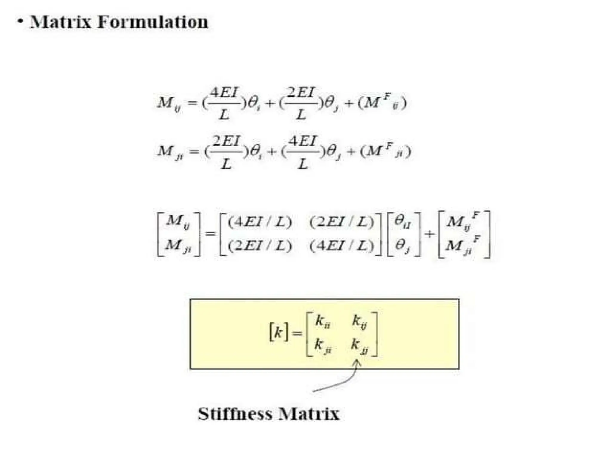
• Stiffness Matrices:
• The core of the method involves developing
stiffness matrices for each member, which relate
the forces at the ends of a member to the
corresponding displacements.
14.
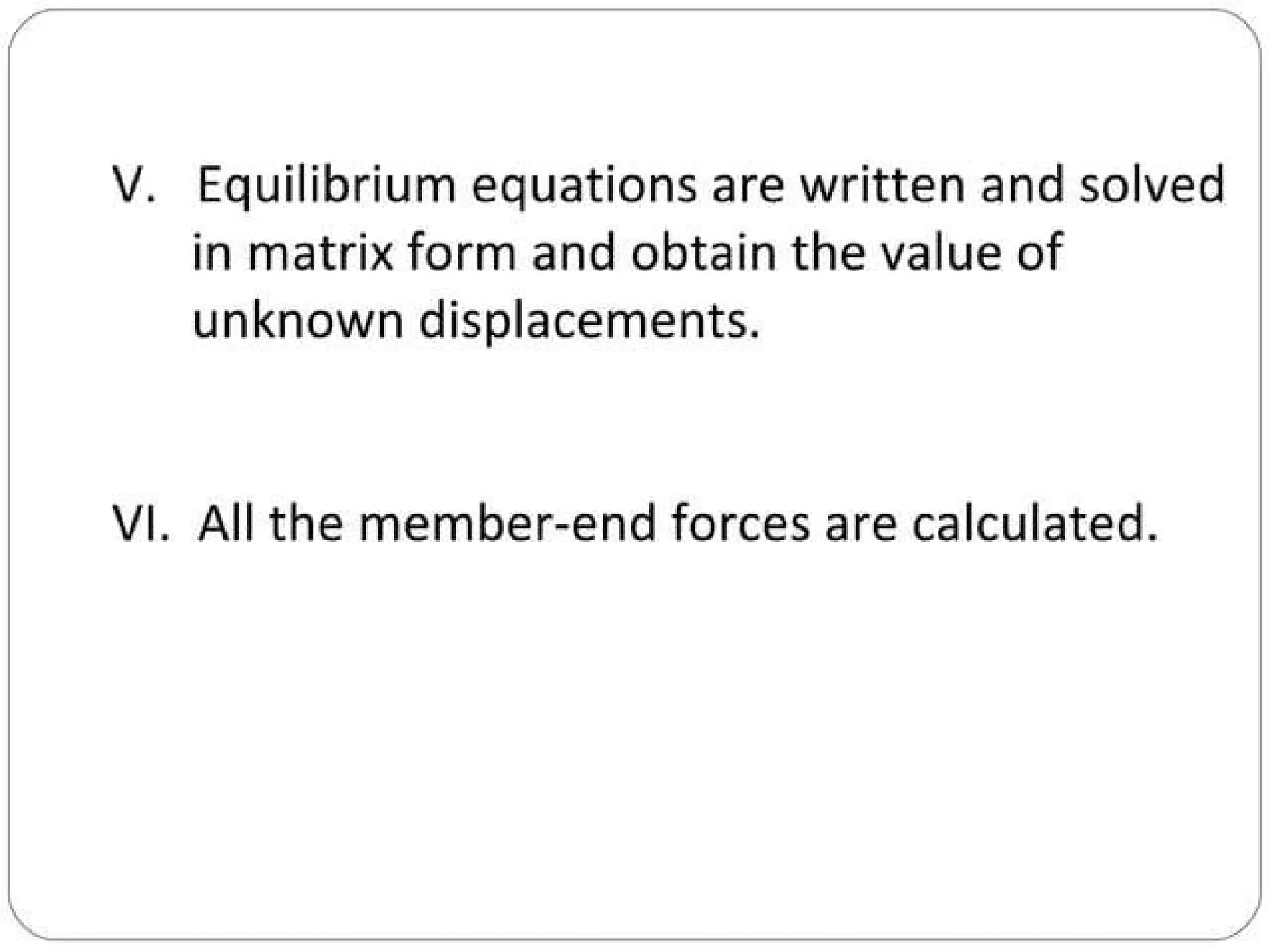
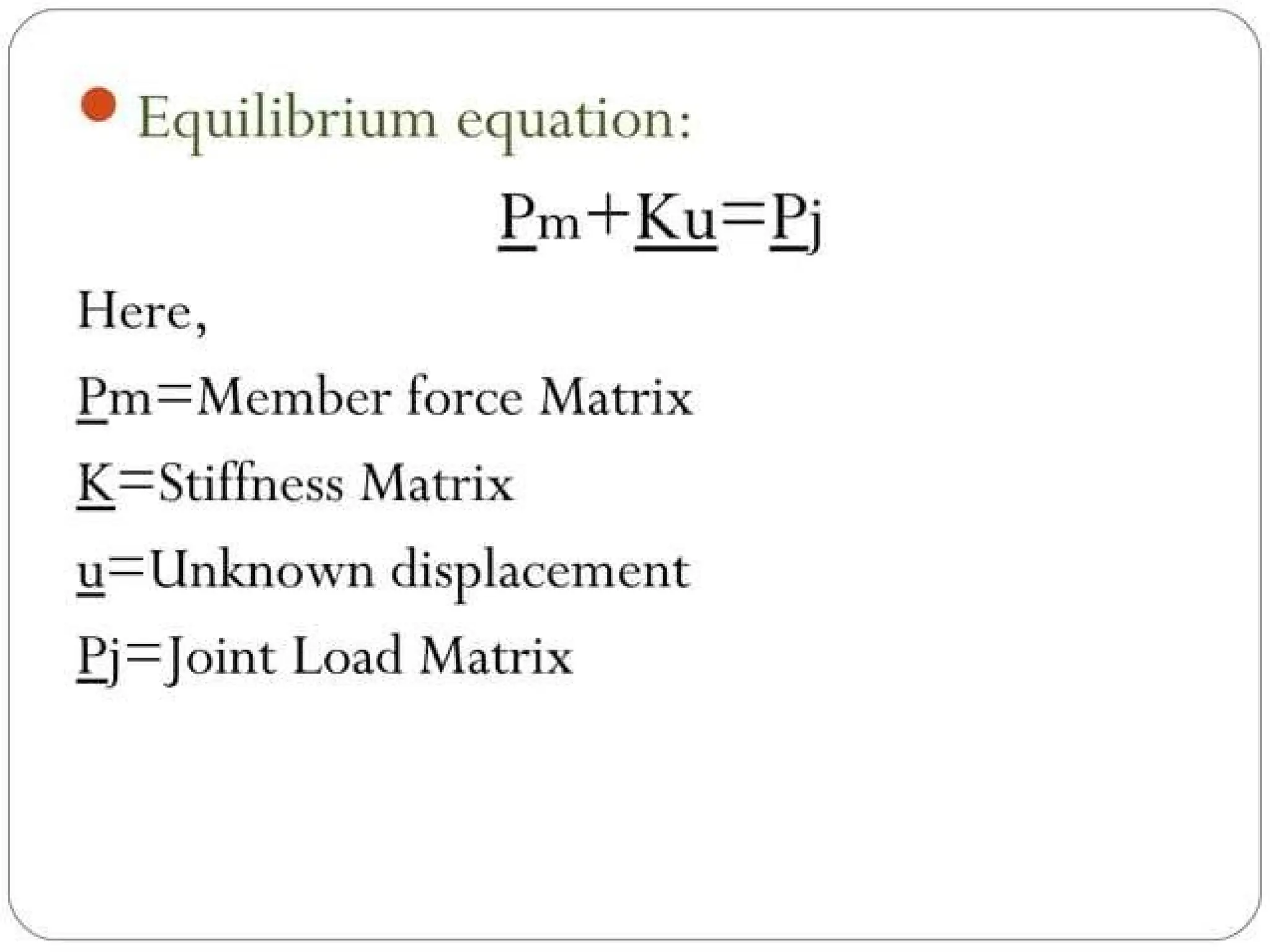
• Global EquilibriumEquations:
• By assembling the member stiffness matrices and
applying equilibrium conditions at the nodes, a
set of global equilibrium equations is established.
• Solving for Unknowns:
• Solving these equations yields the unknown nodal
displacements, which can then be used to
determine the internal forces and stresses within
the structure.
15.
Applications:
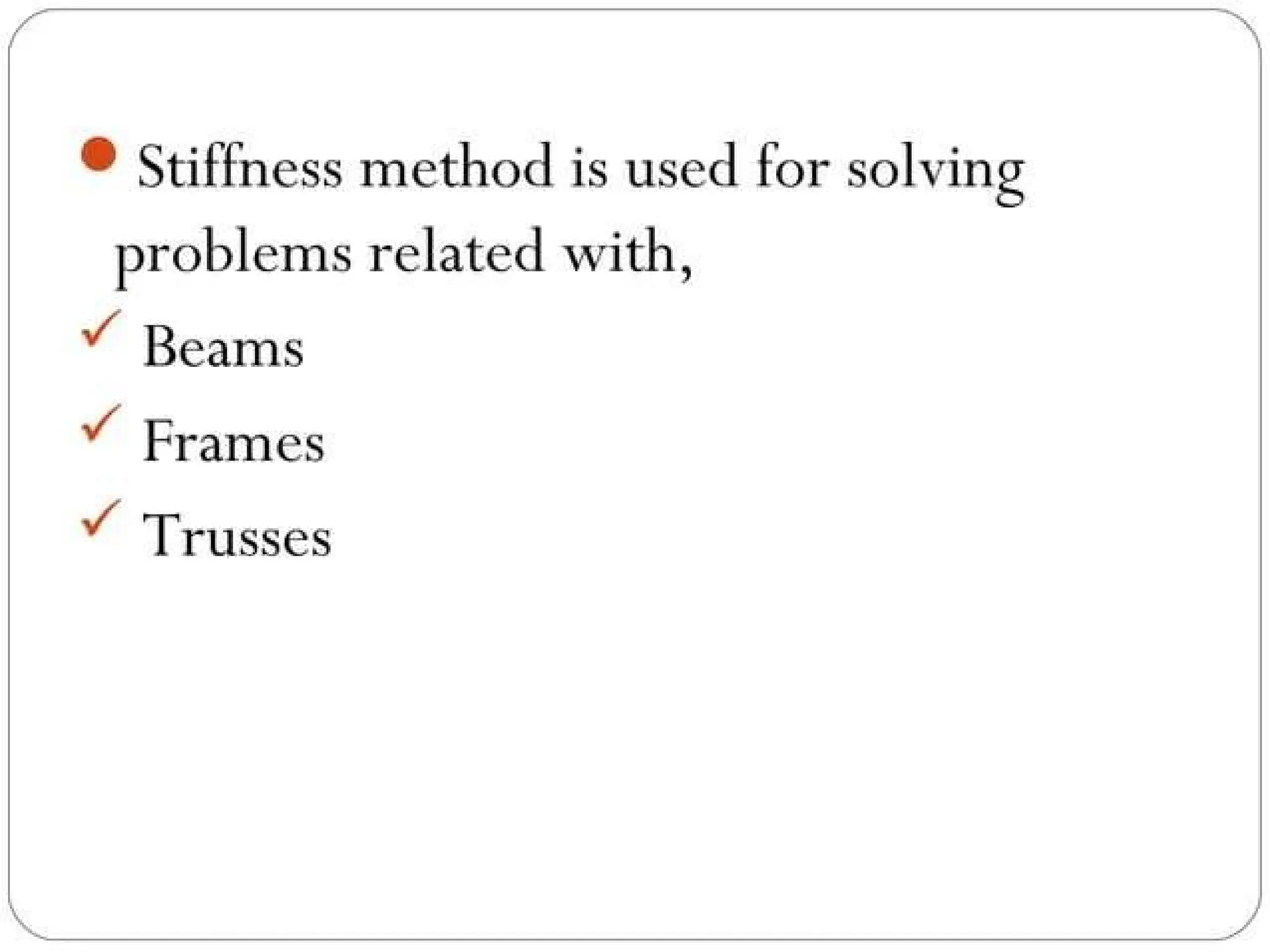
• Analyzing Trusses:
•The stiffness method is particularly well-suited for
analyzing truss structures, where each member
can be represented as a finite element.
• Analyzing Beams and Frames:
• It can also be applied to more complex structures
like beams and frames, by considering the
degrees of freedom at each joint.
16.
Computer-Aided Analysis:
• Thestiffness method forms the basis for most
commercial structural analysis software, enabling the
analysis of complex structures with numerous
members.
• In essence, the stiffness method provides a powerful
and systematic approach for analyzing structures by
focusing on the relationship between displacements
and internal forces, making it a cornerstone of
modern structural engineering analysis.
45.
FINITE ELEMENT METHOD
•Introduction – Discretization of a structure –
Displacement functions – Truss element –
Beam element – Plane stress and plane strain
– Triangular elements.
46.
• The FiniteElement Method (FEM) is a numerical technique for
solving boundary value problems by approximating a continuous
domain with a finite number of smaller, simpler elements
connected at nodes.
• This discretization allows for solving complex problems through a
series of smaller, more manageable equations.
• The method involves defining displacement functions,
formulating element equations, assembling them into a global
system, applying boundary conditions, and solving for unknown
nodal displacements and then calculating stresses and strains.
47.
Introduction to FiniteElement Method
• FEM is a numerical method for solving engineering
problems, particularly those involving complex
geometries, materials, and boundary conditions.
• It breaks down a continuous structure into a finite
number of elements connected at nodes.
• The core idea is to approximate the behavior of the
entire structure by analyzing the behavior of each
element.
• FEM is widely used in structural mechanics, heat
transfer, fluid dynamics, and electromagnetics.
48.
Discretization of aStructure
• Discretization: The process of dividing a continuous domain into a
finite number of smaller, interconnected elements.
• Elements: Simple geometric shapes (e.g., triangles, quadrilaterals,
tetrahedra) that approximate the continuous domain.
• Nodes: Points where elements are connected and where
displacements are defined.
• Mesh: The overall arrangement of elements and nodes in the
discretized domain.
• Example: A complex structure like a bridge or an aircraft wing can
be discretized into a mesh of elements to model its behavior
under stress.
49.
Displacement Functions
• DisplacementFunctions:
• Mathematical functions that describe the displacement of a point
within an element based on the displacements at the element's
nodes.
• Shape Functions:
• A set of functions that, when combined with node displacements,
provide a continuous approximation of the displacement field
within the element.
• Approximation:
• Displacement functions can be linear, quadratic, or higher-order
polynomials, depending on the element type and desired
accuracy.
50.
Element Types
• TrussElement:
• A 1D element used to model structures under axial load, like a bridge
or a building frame.
• Beam Element:
• A 1D element used to model structures that can bend and twist, like a
beam in a bridge or a building floor.
• Plane Stress and Plane Strain Elements:
• 2D elements used to model structures under two-dimensional stress
conditions.
• Triangular Elements:
• 2D elements commonly used in plane stress and plane strain analysis,
particularly due to their flexibility in meshing complex geometries.
51.
Formation of ElementEquations
• Stiffness Matrix: A matrix that relates the
forces acting on an element to the resulting
displacements.
• Load Vector: A vector that represents the
applied loads on the element.
• Element Equations: Equations that describe
the behavior of each element, relating applied
forces to nodal displacements.
52.
Assembly and Solution
•Assembly: Combining the element equations into a global
system of equations that represents the behavior of the
entire structure.
• Global Stiffness Matrix: The combined stiffness matrix for
the entire structure.
• Global Load Vector: The combined load vector for the entire
structure.
• Solution: Solving the global system of equations to
determine the unknown nodal displacements.
• Post-processing: Calculating stresses and strains within each
element based on the determined nodal displacements.
53.
PLASTIC ANALYSIS OFSTRUCTURES
• Statically indeterminate axial problems –
Beams in pure bending – Plastic moment of
resistance – Plastic modulus – Shape factor –
Load factor – Plastic hinge and mechanism –
Plastic analysis of indeterminate beams and
frames – Upper and lower bound theorems.
54.
• Plastic analysisin structural engineering determines the
ultimate or collapse load of a structure by considering the
plastic behavior of materials after yielding.
• It focuses on the structure's capacity to carry load beyond
its elastic limit, utilizing the material's full strength in the
plastic range.
• This method is particularly relevant for steel structures,
where significant plastic deformation before failure is a
characteristic.
55.
• Plastic Hinge:
•A region in a structure where the material
undergoes significant plastic deformation,
allowing for large rotations and redistribution
of moments.
• Plastic Moment (Mp):
• The maximum bending moment a cross-
section can withstand before yielding.
56.
• Shape Factor:
•A value that describes the shape of a cross-section and
relates the plastic moment to the elastic moment.
• Collapse Mechanism:
• A failure mode where plastic hinges form, causing the
structure to collapse under load.
• Collapse Load:
• The load at which the structure reaches its ultimate
capacity and collapses.
57.
Methods for PlasticAnalysis
• Static/Equilibrium Method:
• This method assumes that the structure is in
equilibrium under the applied load and utilizes
the equilibrium conditions to determine the
collapse load.
• Kinematic/Mechanism Method:
• This method considers the possible collapse
mechanisms and uses the virtual work principle
to determine the collapse load.
58.
Applications
• Steel Structures:
•Plastic analysis is widely used for designing steel structures, as
it allows for efficient utilization of material strength.
• Frames and Beams:
• Plastic analysis is particularly useful for analyzing frames and
beams, where plastic hinges can form and redistribute
moments.
• Ultimate Load Design:
• Plastic analysis is a basis for ultimate load design, where the
structure's strength is designed based on its ability to
withstand collapse loads.
59.
Benefits of PlasticAnalysis
• Efficient Material Utilization:
• It allows for a more rational and efficient use of structural
materials by considering their full plastic strength.
• Safety:
• It provides a more accurate assessment of the structure's
capacity and helps ensure safety under extreme loading
conditions.
• Design Optimization:
• It enables designers to optimize structural configurations
and achieve cost-effective designs.
60.
SPACE AND CABLESTRUCTURES
• Analysis of Space trusses using method of
tension coefficients – Beams curved in plan –
Suspension cables – suspension bridges with
two and three hinged stiffening girders.
61.
• The analysisof space trusses, beams curved in plan,
suspension cables, and suspension bridges with different
stiffening girder arrangements involves understanding
their behavior under various loads.
• Space trusses are three-dimensional structures analyzed
using methods like the tension coefficient method. Beams
curved in plan experience bending, shear, and torsion,
while suspension cables primarily experience tension.
• Suspension bridges, with two or three-hinged stiffening
girders, are analyzed to determine cable tension, girder
stresses, and influence lines for various loads.
62.
Space Trusses
• Methodof Tension Coefficients:
• This method is used to analyze the forces in
members of a space truss, taking into account
the three-dimensional nature of the structure.
• Analysis:
• The method involves solving equations of
equilibrium for each node, considering forces
in all three spatial directions.
63.
• Beams Curvedin Plan:
• Behavior:
• These beams experience bending, shear, and
torsional stresses due to their curved geometry.
• Analysis:
• The analysis involves determining bending
moments, shear forces, and torsional moments
at different points along the beam.
64.
• Suspension Cables:
•Tension:
• Suspension cables are designed to withstand only
tensile forces, with no bending or compression.
• Analysis:
• The analysis focuses on determining the tension
in the cable under various loads, as well as the
cable's sag and length.
65.
Suspension Bridges:
• StiffeningGirders: Suspension bridges utilize
stiffening girders to distribute loads from the
deck to the main cables.
• Two-Hinged Girders: These girders have two
hinges and are statically indeterminate.
• Three-Hinged Girders: These girders have
three hinges and are statically determinate.
66.
• Analysis: Theanalysis involves determining the tension in the
cables, stresses in the stiffening girders, and influence lines for
various loads. Influence lines help determine the maximum
forces in different members under a moving load.
• Cable Tension: The tension in the cable is influenced by the load
on the bridge and the geometry of the bridge.
• Girder Stresses: The stresses in the stiffening girder are affected
by the load distribution and the geometry of the girder.
• Influence Lines: Influence lines for bending moment and shear
force in the girders are constructed to determine the maximum
values under a moving load.