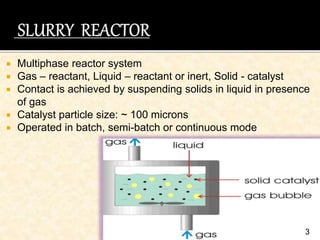
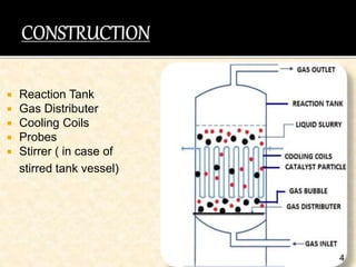
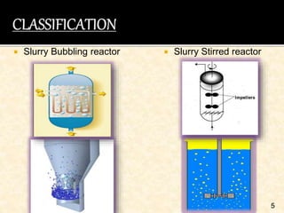
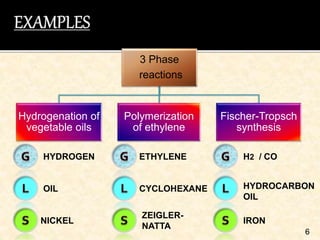
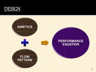
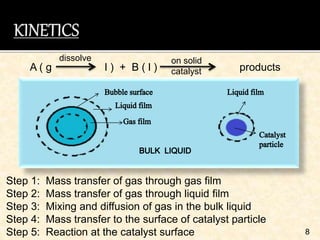
1
SUBMITTED TO:
Dr. BRISHTI MITRA
HEAD OF THE DEPARTMENT
CHEMICAL ENGINEERING
U.I.E.T. , C.S.J.M.U. , KANPUR
SUBMITTED BY:
SUPRIYA GUPTA
CSJMA14001390226
B.TECH , FINAL YEAR
CHEMICAL ENGINEERING
 Introduction
 Construction
 Classification
 Examples
 Design
 Advantages
 Disadvantages
 Applications
 Conclusion
 References
2
 Multiphase reactor system
 Gas – reactant, Liquid – reactant or inert, Solid - catalyst
 Contact is achieved by suspending solids in liquid in presence
of gas
 Catalyst particle size: ~ 100 microns
 Operated in batch, semi-batch or continuous mode
3
 Reaction Tank
 Gas Distributer
 Cooling Coils
 Probes
 Stirrer ( in case of
stirred tank vessel)
4
 Slurry Bubbling reactor  Slurry Stirred reactor
5
6
3 Phase
reactions
Hydrogenation of
vegetable oils
Polymerization
of ethylene
Fischer-Tropsch
synthesis
HYDROGEN
OIL
NICKEL
ETHYLENE
CYCLOHEXANE
ZEIGLER-
NATTA
HYDROCARBON
OIL
H2 / CO
IRON
7
KINETICS
FLOW
PATTERN
PERFORMANCE
EQUATION
Step 1: Mass transfer of gas through gas film
Step 2: Mass transfer of gas through liquid film
Step 3: Mixing and diffusion of gas in the bulk liquid
Step 4: Mass transfer to the surface of catalyst particle
Step 5: Reaction at the catalyst surface 8
A ( g l ) + B ( l ) products
on solid
catalyst
dissolve
Rate observed (r)ob = kg ag (Cg – Cgi)
= kl ag (Cli – Cl)
= kc ac (Cl – Cs)
= k ac Cs 9
10
Global rate expression :
ac Cg
ac + ac H + H + H
ag kg ag kl kc k
ro =
ac = external surface area of catalyst particles per unit .
volume of bubble free liquid
ag = bubble – liquid interfacial area per unit volume of
. . bubble free liquid
kg = gas side mass transfer coefficient
kl = liquid side mass transfer coefficient (bubble – liquid)
kc = liquid side mass transfer coefficient ( liquid – particle)
k = reaction rate constant
H = henry’s law constant ( Cgi = H Cli )
11
Mixed flow G / any flow L Plug flow G / any flow L
F AO X A = (- ro ) Vr F AO dXA = (- ro ) dVr
12
Mixed flow G / Batch L Plug flow G / Batch L
FAO X A = (- ro ) Vr F AO dXA = (- ro ) dVr
 High reaction rate
 Negligible intraparticle diffusion resistance
 Online catalyst addition and removal
 Better temperature control for highly exothermic reactions
 Easy and simple construction
13
 Product separation is
difficult
 Low rate of mass transfer
14
 Hydrogenation
 Oxidation
 Polymerization
 Halogenation
 Fermentation
 Waste water treatment
15
 Advanced reactor technology for G/L processes
 Complex bubble behavior
 Feasible liquid solid separation method – combination
method
16
 O. Levenspiel, Chemical Reaction Engineering, John
Willey & Sons
 J.M. Smith, Chemical Engineering Kinetics, 3rd edition,
McGraw-Hill
 https://nptel.ac.in>module 2> lec 18
 T Wang, J Wang, Y Jin – Industrial & Engineering
Chemistry…,2007- ACS Publications
17
18

Slurry reactor

  • 1.
    1 SUBMITTED TO: Dr. BRISHTIMITRA HEAD OF THE DEPARTMENT CHEMICAL ENGINEERING U.I.E.T. , C.S.J.M.U. , KANPUR SUBMITTED BY: SUPRIYA GUPTA CSJMA14001390226 B.TECH , FINAL YEAR CHEMICAL ENGINEERING
  • 2.
     Introduction  Construction Classification  Examples  Design  Advantages  Disadvantages  Applications  Conclusion  References 2
  • 3.
     Multiphase reactorsystem  Gas – reactant, Liquid – reactant or inert, Solid - catalyst  Contact is achieved by suspending solids in liquid in presence of gas  Catalyst particle size: ~ 100 microns  Operated in batch, semi-batch or continuous mode 3
  • 4.
     Reaction Tank Gas Distributer  Cooling Coils  Probes  Stirrer ( in case of stirred tank vessel) 4
  • 5.
     Slurry Bubblingreactor  Slurry Stirred reactor 5
  • 6.
    6 3 Phase reactions Hydrogenation of vegetableoils Polymerization of ethylene Fischer-Tropsch synthesis HYDROGEN OIL NICKEL ETHYLENE CYCLOHEXANE ZEIGLER- NATTA HYDROCARBON OIL H2 / CO IRON
  • 7.
  • 8.
    Step 1: Masstransfer of gas through gas film Step 2: Mass transfer of gas through liquid film Step 3: Mixing and diffusion of gas in the bulk liquid Step 4: Mass transfer to the surface of catalyst particle Step 5: Reaction at the catalyst surface 8 A ( g l ) + B ( l ) products on solid catalyst dissolve
  • 9.
    Rate observed (r)ob= kg ag (Cg – Cgi) = kl ag (Cli – Cl) = kc ac (Cl – Cs) = k ac Cs 9
  • 10.
    10 Global rate expression: ac Cg ac + ac H + H + H ag kg ag kl kc k ro = ac = external surface area of catalyst particles per unit . volume of bubble free liquid ag = bubble – liquid interfacial area per unit volume of . . bubble free liquid kg = gas side mass transfer coefficient kl = liquid side mass transfer coefficient (bubble – liquid) kc = liquid side mass transfer coefficient ( liquid – particle) k = reaction rate constant H = henry’s law constant ( Cgi = H Cli )
  • 11.
    11 Mixed flow G/ any flow L Plug flow G / any flow L F AO X A = (- ro ) Vr F AO dXA = (- ro ) dVr
  • 12.
    12 Mixed flow G/ Batch L Plug flow G / Batch L FAO X A = (- ro ) Vr F AO dXA = (- ro ) dVr
  • 13.
     High reactionrate  Negligible intraparticle diffusion resistance  Online catalyst addition and removal  Better temperature control for highly exothermic reactions  Easy and simple construction 13
  • 14.
     Product separationis difficult  Low rate of mass transfer 14
  • 15.
     Hydrogenation  Oxidation Polymerization  Halogenation  Fermentation  Waste water treatment 15
  • 16.
     Advanced reactortechnology for G/L processes  Complex bubble behavior  Feasible liquid solid separation method – combination method 16
  • 17.
     O. Levenspiel,Chemical Reaction Engineering, John Willey & Sons  J.M. Smith, Chemical Engineering Kinetics, 3rd edition, McGraw-Hill  https://nptel.ac.in>module 2> lec 18  T Wang, J Wang, Y Jin – Industrial & Engineering Chemistry…,2007- ACS Publications 17
  • 18.