Downloaded 4,328 times


![Slope Stability Numerical
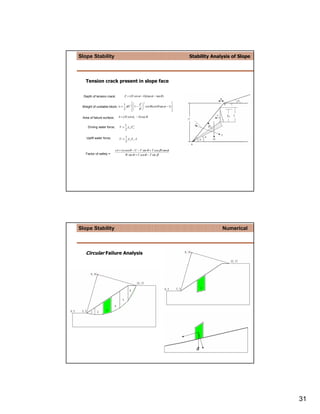
Circular Failure Analysis
FOS = c+σ tan
φ
τs
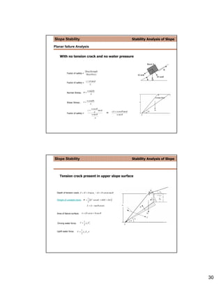
Slope Stability Stability Analysis of Slope
Circular Failure Analysis
FOS = c+σtan
φ
τ = c + σ tan φ
τs
w cos θ
c+ tan φ Wn
∆L c∆L + w cos θ tan φ
FOS = =
w sin θ w sin θ
∆L
n= p
∑ [c∆L
n =1
n + Wn cos α n tan φ ]
FOS = n= p
∑ [W
n =1
n sin α n ]
32](https://image.slidesharecdn.com/slopestability-110506063321-phpapp02/85/Slopestability-32-320.jpg)


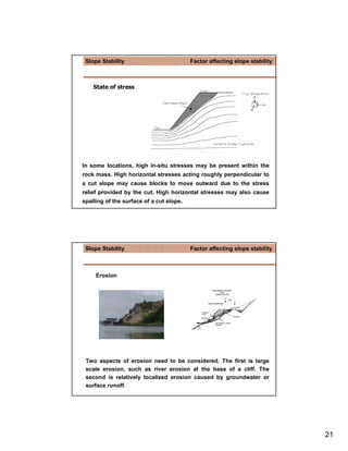
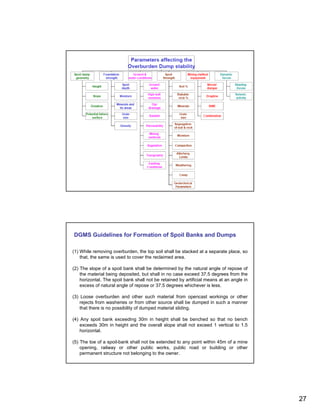
The document discusses the significance of slope stability in mining, detailing types of slope failures, factors affecting stability, and methods of analysis. Key issues include geological conditions, hydrological influences, and industry guidelines for safe excavation practices. It emphasizes the importance of accurate modeling and monitoring to prevent failures and ensure economic efficiency in open-pit mining operations.


