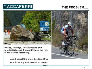
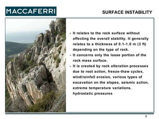
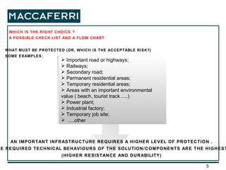
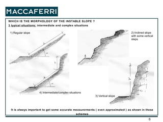
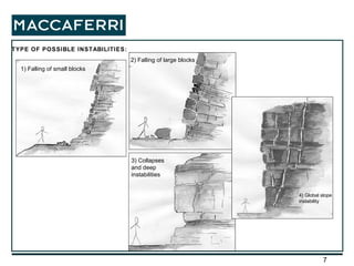
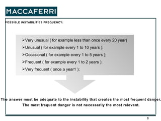
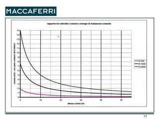
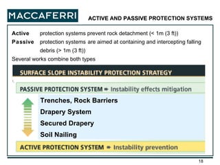
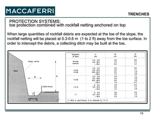
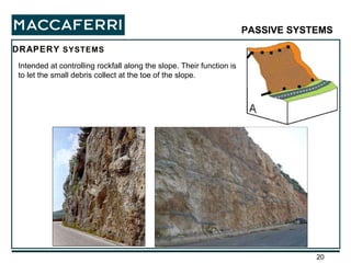
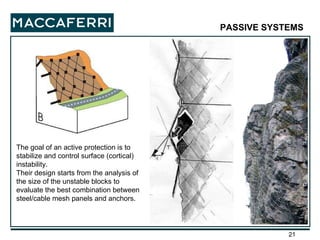
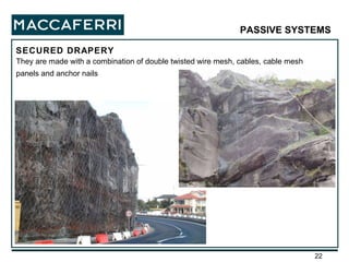
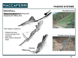
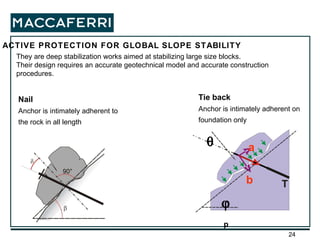
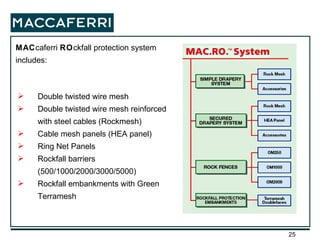
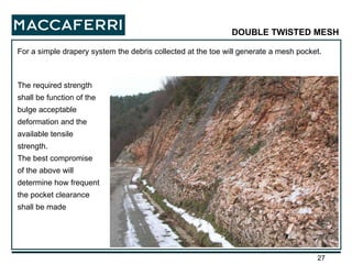
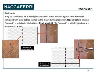
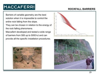
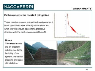
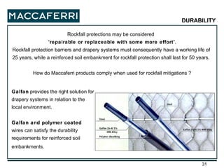
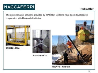
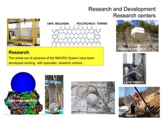
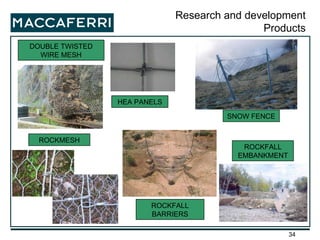
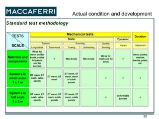
Rockfall mitigation, problems and solutions: The MACRO System
Roads, railways, infrastructure and residential areas frequently face the risk of rock slope instability. .. and something must be done if we want to safely use roads and protect lives! THE PROBLEM….
A rockfall mitigation is a very complex project because very often it is made from the combination of revetments, rockfall fences and/or rockfall embankments, with an alternative of the various protections systems without a constant rule. The designer must start from the risk analysis, considering the available founding, verifying the feasibility of the revetments and/or the rock fences in relationship with the morphology of the slope, the surrounding presence of buildings and roads and at the end, choosing the types of products to be used. The goal of this presentation is to give several general suggestions: we are aware of the reality that in few minutes it is not possible to become an expert, but certainly we can upgrade our understanding of the problem in order to have a proper design.
- It relates to the rock surface without affecting the overall stability. It generally relates to a thickness of 0.1-1.0 m (3 ft) depending on the type of rock. - It concerns only the loose portion of the rock mass surface. - It is created by rock alteration processes due to root action, freeze-thaw cycles, wind/rainfall erosion, various types of excavation on the slopes, seismic action, extreme temperature variations, hydrostatic pressures SURFACE INSTABILITY
Important road or highways; Railways; Secondary road; Permanent residential areas; Temporary residential areas; Areas with an important environmental value ( beach, tourist track…..) Power plant; Industrial factory; Temporary job site; … .other WHAT MUST BE PROTECTED (OR, WHICH IS THE ACCEPTABLE RISK?) SOME EXAMPLES: AN IMPORTANT INFRASTRUCTURE REQUIRES A HIGHER LEVEL OF PROTECTION . THE REQUIRED TECHNICAL BEHAVIOURS OF THE SOLUTION/COMPONENTS ARE THE HIGHEST. (HIGHER RESISTANCE AND DURABILITY) WHICH IS THE RIGHT CHOICE ? A POSSIBLE CHECK LIST AND A FLOW CHART
WHICH IS THE MORPHOLOGY OF THE INSTABLE SLOPE ?  3 typical situations;  intermediate and complex situations It is always important to get some accurate measurerments ( even approximated ) as shown in these schemes 3) Vertical slope 1) Regular slope 2) Inclined slope with some vertical steps 4) Intermediate/complex situations
TYPE OF POSSIBLE INSTABILITIES: 1) Falling of small blocks 3) Collapses and deep instabilities 2) Falling of large blocks 4) Global slope instability
POSSIBLE INSTABILITIES FREQUENCY: Very unusual ( for example less than once every 20 year) Unusual ( for example every 1 to 10 years ); Occasional ( for example every 1 to 5 years ); Frequent ( for example every 1 to 2 years ); Very frequent ( once a year1 ); The answer must be adequate to the instability that creates the most frequent danger. The most frequent danger is not necessarily the most relevant.
THE ENVIRONMENTAL PROBLEMS INTERFERING WITH THE SOLUTION: Marine environment Rocks containing chalk, pyrite etc  Presence of aggressive natural gasses (ex. H 2 S volcanic) or industrial Fire danger Snow avalanches danger Vicinity of streams, drainage channels etc All these factors can influence the duration and the efficiency of the intervention
PROBLEMS INTERFERING WITH THE INSTALLATION PROCEDURES: The best season for the execution of the job (presence of snow, seasonal rainfall etc ) Safety requirements for the workers (rockfall danger during the installation etc) Job site ease of access ( presence of roads),  Job site with a difficult access (lack of roads and/or very high rock slope: need of placing with a helicopter) In some situations it is sometimes impossible to work. Or , if it possible that the timing of the execution can be very long. All these factors influence the final cost.
DURING THE INSTALLATION IT IS IMPORTANT TO VERIFY  IF: It is possible to remove unstable blocks by scaling It is possible to cut trees before the meshes installation Access roads are in relationship with the slope to be protected. It is possible or needed to use  a helicopter ( analyzing the possible restriction due to the presence of electrical lines etc. ) Road
THE URGENT NEED OF MAKING THE PROTECTION It is critical to evaluate the timing of the construction phases. FREQUENT FALLS OCCASIONAL FALLS Very high slope with large block with low frequency ( low risk ) or small blocks with very high frequency ( high risk  ): The solution is a rockfall barrier. Probably, the design  cannot contain all the large blocks, but prevents the risk.
DURABILITY OF THE PROTECTION Temporary protections For short  time protections of building yards or infrastructures  The design safety factors may be lower and the technical specifications of the materials used may not be at the highest level (Corrosion Protection). Permanent protections For roads, railways and urban areas The design safety factors must be reasonably high and the technical specifications of the materials used must be the best. The different durability is managed by the change in the safety factors and in the technical specifications of the materials.
THE REQUIREMENTS OF THE MAINTENANCE During the life of the protection the maintenance procedures can require:  Periodical visual inspections to check meshes and barriers Survey by rock climbers Periodical removal of the debris at the back of barriers or embankments Periodical removal of the debris at the bottom of simple drapery systems Repair of the passive protections ( closing  possible broke meshes ) Repair of the active-passive protections ( checking the situation of the anchoring system ) Maintenance grants the protection efficiency. The customer must be informed about the maintenance requirements.
ROCKFALL THE BORDER CONDITIONS AND THE APPROACH METHODOLOGIES THE PARAMETERS AFFECTING THE DESIGN OF A PASSIVE PROTECTION:  FALLING ENERGY FALLING SPEED HEIGHT OF IMPACT BEST POSITION ALONG THE SLOPE OPERATIVE PROBLEMS DURING THE INSTALLATION
THE FALLING ENERGY  The falling energy is given from the rotational energy and translational one  E = E   + Ek where: E    = ½ I   2  (I = inertial moment;   = angular rotational speed)   Ek = ½ M v 2  (M = block weight; v=translational speed)  The most important energy is the translational one that normally is at least around the 80% of the total kinetic energy. The rotational energy is around the 10-20% of the total one and is in relationship with the shape of the block. Normally squared block have a very low rotational energy.
 
Active  protection systems prevent rock detachment (< 1m (3 ft)) Passive  protection systems   are aimed at containing and intercepting falling debris (> 1m (3 ft)) Several works combine both types ACTIVE  AND  PASSIVE  PROTECTION SYSTEMS Trenches, Rock Barriers Drapery System Secured Drapery Soil Nailing
When large quantities of rockfall debris are expected at the toe of the slope, the rockfall netting will be placed at 0.3-0.6 m  (1 to 2 ft) away from the toe surface. In order to intercept the debris, a collecting ditch may be built at the toe . PROTECTION SYSTEMS:  toe protection combined with rockfall netting anchored on top TRENCHES
Intended at controlling rockfall along the slope. Their function is to let the small debris collect at the toe of the slope. DRAPERY  SYSTEMS PASSIVE SYSTEMS
The goal of an active protection is to stabilize and control surface (cortical) instability. Their design starts from the analysis of the size of the unstable blocks to evaluate the best combination between steel/cable mesh panels and anchors. PASSIVE SYSTEMS
SECURED DRAPERY PASSIVE SYSTEMS   They are made with a combination of double twisted wire mesh, cables, cable mesh panels and anchor nails
ROCKFALL EMBANKMENTS Rockfall barriers Ditches PASSIVE SYSTEMS   Flexible barrier fences Structures aimed at catching and stopping the falling rock. Their design is based on: Global rock sizes Level of energy to be absorbed Best position along the slope
They are deep stabilization works aimed at stabilizing large size blocks. Their design requires an accurate geotechnical model and accurate construction procedures. ACTIVE PROTECTION FOR GLOBAL SLOPE STABILITY Tie back   Anchor is intimately adherent on foundation only Nail Anchor is intimately adherent to the rock in all length T   p a b
MAC caferri  RO ckfall protection system includes: Double twisted wire mesh Double twisted wire mesh reinforced with steel cables (Rockmesh) Cable mesh panels (HEA panel) Ring Net Panels Rockfall barriers (500/1000/2000/3000/5000) Rockfall embankments with Green Terramesh
The approach of  MAC.RO.  is to provide a variety of solutions with specific design methodologies. Not only a series of products. The key factors leading to the correct protection system are: The evaluation of the required strength parameters for the protection to be used The weight of the volume of debris at the toe of the slope  The energy to be absorbed by the barrier  The strength and the stiffness required to keep a certain block in place  The stress transferred to the anchors The consideration of  “boundary conditions” around the protection: for example the max deformation of the netting of a barrier after the impact.
For a simple drapery system the debris collected at the toe will generate a mesh pocket.  DOUBLE TWISTED MESH The required strength shall be function of the bulge acceptable deformation and the available tensile strength. The best compromise of the above will determine how frequent the pocket clearance shall be made
Rockmesh may be considered as a “steel geocomposite” made with hexagonal steel wire mesh combined with steel cables twisted in the mesh during production.  RockMesh M  (“Mono Oriented”) is with horizontal cables.  RockMesh B  (“Bi Oriented”) is with longitudinal and transversal cables. Rochmesh  B  BI-ORIENTED Rockmesh M  MONO-ORIENTED ROCKMESH
Barriers of variable geometry are the best solution when it is impossible to control the entire rock falling from the slope. They can be chosen in relation to the energy of the rock falling phenomena. Maccaferri developed and tested a wide range of barriers from 500 up to 5000 kJ and can provide all the specific installation procedures. ROCKFALL BARRIERS
Embankments for rockfall mitigation These passive systems are an ideal solution when it is not possible to work  directly on the slope and when there is enough space for a protective structure with the best environmental benefit. Green Terramesh  units are an excellent solution due to the flexibility of the system, the natural greening and ease of installation EMBANKMENTS
Rockfall protections may be considered  “ repairable or replaceable with some more effort ”. Rockfall protection barriers and drapery systems must consequently have a working life of 25 years, while a reinforced soil embankment for rockfall protection shall last for 50 years. How do Maccaferri products comply when used for rockfall mitigations ? Galfan  provides the right solution for drapery systems in relation to the local environment. Galfan and polymer coated  wires can satisfy the durability requirements for reinforced soil embankments.   DURABILITY
The entire range of solutions provided by MAC.RO. Systems have been developed in cooperation with Research Institutes. CNR/ITC - Milan LATIF TRENTO TRENTO – field test RESEARCH
Research The whole set of solutions of the MACRO System have been developed working  with specialist  research centres Research and Development Research centers CEMAGREF  GRENOBLE CNR/ITC – MILANO TRENTO UNIV. BOLOGNA  POLITECNICO  TORINO PONT BOSET FONZASO CTR FIELD LATIF TRENTO
DOUBLE TWISTED WIRE MESH ROCKMESH ROCKFALL BARRIERS HEA PANELS ROCKFALL EMBANKMENT Research and development Products SNOW FENCE
Standard test methodology  Actual condition and development

1 Macro Intro 2008

  • 1.
    Rockfall mitigation, problemsand solutions: The MACRO System
  • 2.
    Roads, railways, infrastructureand residential areas frequently face the risk of rock slope instability. .. and something must be done if we want to safely use roads and protect lives! THE PROBLEM….
  • 3.
    A rockfall mitigationis a very complex project because very often it is made from the combination of revetments, rockfall fences and/or rockfall embankments, with an alternative of the various protections systems without a constant rule. The designer must start from the risk analysis, considering the available founding, verifying the feasibility of the revetments and/or the rock fences in relationship with the morphology of the slope, the surrounding presence of buildings and roads and at the end, choosing the types of products to be used. The goal of this presentation is to give several general suggestions: we are aware of the reality that in few minutes it is not possible to become an expert, but certainly we can upgrade our understanding of the problem in order to have a proper design.
  • 4.
    - It relatesto the rock surface without affecting the overall stability. It generally relates to a thickness of 0.1-1.0 m (3 ft) depending on the type of rock. - It concerns only the loose portion of the rock mass surface. - It is created by rock alteration processes due to root action, freeze-thaw cycles, wind/rainfall erosion, various types of excavation on the slopes, seismic action, extreme temperature variations, hydrostatic pressures SURFACE INSTABILITY
  • 5.
    Important road orhighways; Railways; Secondary road; Permanent residential areas; Temporary residential areas; Areas with an important environmental value ( beach, tourist track…..) Power plant; Industrial factory; Temporary job site; … .other WHAT MUST BE PROTECTED (OR, WHICH IS THE ACCEPTABLE RISK?) SOME EXAMPLES: AN IMPORTANT INFRASTRUCTURE REQUIRES A HIGHER LEVEL OF PROTECTION . THE REQUIRED TECHNICAL BEHAVIOURS OF THE SOLUTION/COMPONENTS ARE THE HIGHEST. (HIGHER RESISTANCE AND DURABILITY) WHICH IS THE RIGHT CHOICE ? A POSSIBLE CHECK LIST AND A FLOW CHART
  • 6.
    WHICH IS THEMORPHOLOGY OF THE INSTABLE SLOPE ? 3 typical situations; intermediate and complex situations It is always important to get some accurate measurerments ( even approximated ) as shown in these schemes 3) Vertical slope 1) Regular slope 2) Inclined slope with some vertical steps 4) Intermediate/complex situations
  • 7.
    TYPE OF POSSIBLEINSTABILITIES: 1) Falling of small blocks 3) Collapses and deep instabilities 2) Falling of large blocks 4) Global slope instability
  • 8.
    POSSIBLE INSTABILITIES FREQUENCY:Very unusual ( for example less than once every 20 year) Unusual ( for example every 1 to 10 years ); Occasional ( for example every 1 to 5 years ); Frequent ( for example every 1 to 2 years ); Very frequent ( once a year1 ); The answer must be adequate to the instability that creates the most frequent danger. The most frequent danger is not necessarily the most relevant.
  • 9.
    THE ENVIRONMENTAL PROBLEMSINTERFERING WITH THE SOLUTION: Marine environment Rocks containing chalk, pyrite etc Presence of aggressive natural gasses (ex. H 2 S volcanic) or industrial Fire danger Snow avalanches danger Vicinity of streams, drainage channels etc All these factors can influence the duration and the efficiency of the intervention
  • 10.
    PROBLEMS INTERFERING WITHTHE INSTALLATION PROCEDURES: The best season for the execution of the job (presence of snow, seasonal rainfall etc ) Safety requirements for the workers (rockfall danger during the installation etc) Job site ease of access ( presence of roads), Job site with a difficult access (lack of roads and/or very high rock slope: need of placing with a helicopter) In some situations it is sometimes impossible to work. Or , if it possible that the timing of the execution can be very long. All these factors influence the final cost.
  • 11.
    DURING THE INSTALLATIONIT IS IMPORTANT TO VERIFY IF: It is possible to remove unstable blocks by scaling It is possible to cut trees before the meshes installation Access roads are in relationship with the slope to be protected. It is possible or needed to use a helicopter ( analyzing the possible restriction due to the presence of electrical lines etc. ) Road
  • 12.
    THE URGENT NEEDOF MAKING THE PROTECTION It is critical to evaluate the timing of the construction phases. FREQUENT FALLS OCCASIONAL FALLS Very high slope with large block with low frequency ( low risk ) or small blocks with very high frequency ( high risk ): The solution is a rockfall barrier. Probably, the design cannot contain all the large blocks, but prevents the risk.
  • 13.
    DURABILITY OF THEPROTECTION Temporary protections For short time protections of building yards or infrastructures The design safety factors may be lower and the technical specifications of the materials used may not be at the highest level (Corrosion Protection). Permanent protections For roads, railways and urban areas The design safety factors must be reasonably high and the technical specifications of the materials used must be the best. The different durability is managed by the change in the safety factors and in the technical specifications of the materials.
  • 14.
    THE REQUIREMENTS OFTHE MAINTENANCE During the life of the protection the maintenance procedures can require: Periodical visual inspections to check meshes and barriers Survey by rock climbers Periodical removal of the debris at the back of barriers or embankments Periodical removal of the debris at the bottom of simple drapery systems Repair of the passive protections ( closing possible broke meshes ) Repair of the active-passive protections ( checking the situation of the anchoring system ) Maintenance grants the protection efficiency. The customer must be informed about the maintenance requirements.
  • 15.
    ROCKFALL THE BORDERCONDITIONS AND THE APPROACH METHODOLOGIES THE PARAMETERS AFFECTING THE DESIGN OF A PASSIVE PROTECTION: FALLING ENERGY FALLING SPEED HEIGHT OF IMPACT BEST POSITION ALONG THE SLOPE OPERATIVE PROBLEMS DURING THE INSTALLATION
  • 16.
    THE FALLING ENERGY The falling energy is given from the rotational energy and translational one E = E  + Ek where: E  = ½ I  2 (I = inertial moment;  = angular rotational speed) Ek = ½ M v 2 (M = block weight; v=translational speed) The most important energy is the translational one that normally is at least around the 80% of the total kinetic energy. The rotational energy is around the 10-20% of the total one and is in relationship with the shape of the block. Normally squared block have a very low rotational energy.
  • 17.
  • 18.
    Active protectionsystems prevent rock detachment (< 1m (3 ft)) Passive protection systems are aimed at containing and intercepting falling debris (> 1m (3 ft)) Several works combine both types ACTIVE AND PASSIVE PROTECTION SYSTEMS Trenches, Rock Barriers Drapery System Secured Drapery Soil Nailing
  • 19.
    When large quantitiesof rockfall debris are expected at the toe of the slope, the rockfall netting will be placed at 0.3-0.6 m (1 to 2 ft) away from the toe surface. In order to intercept the debris, a collecting ditch may be built at the toe . PROTECTION SYSTEMS: toe protection combined with rockfall netting anchored on top TRENCHES
  • 20.
    Intended at controllingrockfall along the slope. Their function is to let the small debris collect at the toe of the slope. DRAPERY SYSTEMS PASSIVE SYSTEMS
  • 21.
    The goal ofan active protection is to stabilize and control surface (cortical) instability. Their design starts from the analysis of the size of the unstable blocks to evaluate the best combination between steel/cable mesh panels and anchors. PASSIVE SYSTEMS
  • 22.
    SECURED DRAPERY PASSIVESYSTEMS They are made with a combination of double twisted wire mesh, cables, cable mesh panels and anchor nails
  • 23.
    ROCKFALL EMBANKMENTS Rockfallbarriers Ditches PASSIVE SYSTEMS Flexible barrier fences Structures aimed at catching and stopping the falling rock. Their design is based on: Global rock sizes Level of energy to be absorbed Best position along the slope
  • 24.
    They are deepstabilization works aimed at stabilizing large size blocks. Their design requires an accurate geotechnical model and accurate construction procedures. ACTIVE PROTECTION FOR GLOBAL SLOPE STABILITY Tie back Anchor is intimately adherent on foundation only Nail Anchor is intimately adherent to the rock in all length T   p a b
  • 25.
    MAC caferri RO ckfall protection system includes: Double twisted wire mesh Double twisted wire mesh reinforced with steel cables (Rockmesh) Cable mesh panels (HEA panel) Ring Net Panels Rockfall barriers (500/1000/2000/3000/5000) Rockfall embankments with Green Terramesh
  • 26.
    The approach of MAC.RO. is to provide a variety of solutions with specific design methodologies. Not only a series of products. The key factors leading to the correct protection system are: The evaluation of the required strength parameters for the protection to be used The weight of the volume of debris at the toe of the slope The energy to be absorbed by the barrier The strength and the stiffness required to keep a certain block in place The stress transferred to the anchors The consideration of “boundary conditions” around the protection: for example the max deformation of the netting of a barrier after the impact.
  • 27.
    For a simpledrapery system the debris collected at the toe will generate a mesh pocket. DOUBLE TWISTED MESH The required strength shall be function of the bulge acceptable deformation and the available tensile strength. The best compromise of the above will determine how frequent the pocket clearance shall be made
  • 28.
    Rockmesh may beconsidered as a “steel geocomposite” made with hexagonal steel wire mesh combined with steel cables twisted in the mesh during production. RockMesh M (“Mono Oriented”) is with horizontal cables. RockMesh B (“Bi Oriented”) is with longitudinal and transversal cables. Rochmesh B BI-ORIENTED Rockmesh M MONO-ORIENTED ROCKMESH
  • 29.
    Barriers of variablegeometry are the best solution when it is impossible to control the entire rock falling from the slope. They can be chosen in relation to the energy of the rock falling phenomena. Maccaferri developed and tested a wide range of barriers from 500 up to 5000 kJ and can provide all the specific installation procedures. ROCKFALL BARRIERS
  • 30.
    Embankments for rockfallmitigation These passive systems are an ideal solution when it is not possible to work directly on the slope and when there is enough space for a protective structure with the best environmental benefit. Green Terramesh units are an excellent solution due to the flexibility of the system, the natural greening and ease of installation EMBANKMENTS
  • 31.
    Rockfall protections maybe considered “ repairable or replaceable with some more effort ”. Rockfall protection barriers and drapery systems must consequently have a working life of 25 years, while a reinforced soil embankment for rockfall protection shall last for 50 years. How do Maccaferri products comply when used for rockfall mitigations ? Galfan provides the right solution for drapery systems in relation to the local environment. Galfan and polymer coated wires can satisfy the durability requirements for reinforced soil embankments. DURABILITY
  • 32.
    The entire rangeof solutions provided by MAC.RO. Systems have been developed in cooperation with Research Institutes. CNR/ITC - Milan LATIF TRENTO TRENTO – field test RESEARCH
  • 33.
    Research The wholeset of solutions of the MACRO System have been developed working with specialist research centres Research and Development Research centers CEMAGREF GRENOBLE CNR/ITC – MILANO TRENTO UNIV. BOLOGNA POLITECNICO TORINO PONT BOSET FONZASO CTR FIELD LATIF TRENTO
  • 34.
    DOUBLE TWISTED WIREMESH ROCKMESH ROCKFALL BARRIERS HEA PANELS ROCKFALL EMBANKMENT Research and development Products SNOW FENCE
  • 35.
    Standard test methodology Actual condition and development

Editor's Notes

  • #2 2
  • #3 2
  • #4 2
  • #5 2
  • #6 2
  • #7 2
  • #8 2
  • #9 2
  • #10 2
  • #11 2
  • #12 2
  • #13 2
  • #14 2
  • #15 2
  • #16 2
  • #17 2
  • #18 2
  • #19 2
  • #21 2
  • #22 2
  • #23 2
  • #24 2
  • #25 2
  • #26 2
  • #27 2
  • #28 2
  • #29 2
  • #30 2
  • #31 2
  • #32 2
  • #33 2
  • #35 Failure will often occur in rigid structures when combined with moving water. Piping can quickly occur when water is not restricted to flow along the soil surface. As soil is washed away there is more room for water to flow and hence velocities increase leading to more soil to be washed away. Gabions and Reno mattresses prevent this from occuring by deflecting with the soil. This prevents cavities from forming - maintaining contact with the soil as a result the water velocity is reduced as water flows through the mattress Because gabions are flexible there is no concentration of stress. As a load is applied the Gabions are free to redistribute the forces and hence minimise any overstressing. Being free draining, there is no build up of pore pressure behind the structure This also permits the free flow of water through the structure allowing plants to maintian access water. Because of these natural advantages, Gabions have been in use for over 100years
  • #36 2