SlideShare a Scribd company logo
1 of 59
Download to read offline
ROCK EXCAVATION MACHINES – UNDER
            GROUND
              U.Siva Sankar
            Sr. Under Manager
            Project Planning
     Singareni Collieries Company Ltd

      E-Mail :ulimella@gmail.com or
          uss_7@yahoo.com
                  Visit at:
  www.slideshare.net/sankarsulimella


   Mechanical            Rock Excavation


                                           1
Mechanical Excavation Systems
   Different mechanical excavation systems, like machines with;
     Teeth (Dozer, Shovel, Scraper, Bucket wheel excavator, Bucket chain excavator)
     Ripping tool (Coal Plough, ripper, rock breaker),
     Pick mounted rotary cutting head/drum (Roadheader, Shearer, Continuous
     miner, Surface miner)
     Disc cutters and button bits (rock drill, Mobile tunnel miner, Tunnel boring
     machine)
     Auger tool (Continuous Auger Miner, Surface Auger Miner)

 Application of Mechanical Systems
   Under Ground:
       Continuous Miners, Bolter miners, Auger Miners and shearers for coal or soft
       nonmetalics
       Boom type miners (road headers in soft to medium hard rocks)
       Rapid excavation equipment (Mobile tunnel miners,Tunner borers, raise borers,
       and shaft sinking rigs) for soft to medium hard and hard rocks)
   Surface:
       Rippers for very compact soil, coal, and weathered or soft rock
       Bucket wheel and cutting head excavators for soil or coal
       Augers and highwall miners for coal
       Mechanical dredges for placers and soil


Classification of Underground mechanical excavator by rock type


    Hard rock         Soft rock
    1.Roadheader      1.Roadheader
    2.TBM             2.Continuous Miner
    3.Mobile Miner    3.Shearer
    4.Raise Borer

Comparison of mechanical excavation with drill and blast systems

                Advantages                                 Disadvantages

• Generally gives more rapid advance than    • Cannot excavate very hard rock
  blasting in soft to medium-hard rock.
                                             • High capital cost
• Fewer unit operations
                                             • Require specialist maintenance
• Smoother excavation profiles
                                             • Not as flexible
• No blasting damage to surrounding rock

• Inherently safer


                                                                                       2
Parameters influencing applicability of mechanical miners

    The decision to introduce a mechanical miner is generally based on the
    predicted performance of the selected machine in the given geological and
    operational conditions.
    Since it is usually not possible to change the geological conditions, a
    thorough study of the geological and geotechnical parameters (rock mass
    and intact rock properties) at the feasibility and planning stages should be
    carried out to match the machine and operational parameters to the
    geological conditions.
 Machine considerations
   The general technical requirements of excavation machines, in addition to
   safety and economy, are selective mining ability, flexibility, mobility and hard
   and abrasive rock-cutting ability.
   Selective mining ability is the ability to cut selectively in mixed face
   conditions so that the mineral can be excavated separately, reducing
   dilution.
   Mobility means easy relocation of machines from one face to another, when
   necessary.
   Flexibility means easy adaptability to changing operational conditions,
   such as face cross-section shape (horseshoe, rectangular, circular,
   etc.), gradient, turning radius and unevenness of the floor.


Machine considerations
  Hard and abrasive rock-cutting ability is the most important limiting factor on
  the performance of mechanical miners; applications show that strength,
  texture, etc., of the geological environment are the basic input parameters for
  the selection of mechanical miners and performance prediction. the most
  efficient type of tool in hard and abrasive rock.

Geological and geotechnical considerations
  Rock mass features (such as joint sets, bedding planes, foliation, hydro
  geological conditions, deposit geometry, etc.) and intact rock properties (such
  as cuttability, abrasiveness etc).
Operational considerations
  Mine layouts and development drivages are planned in accordance with the
  mining method, which is selected on the basis of orebody shape and
  dimensions and other deposit characteristics.

   For reliable, economic operation the characteristics and layout features of
   a mechanical miner should reflect whether it is to be used for the
   excavation of drifts or for ore/mineral. The layout might be modified for a
   particular mechanical miner if necessary.

   The back-up equipment (such as muck transportation, support, etc.) selected
   for a new mine must be chosen to be compatible with the mechanical miner.
   In an existing mining operation, however, the machine might be selected on
   the basis of the equipment already in use.


                                                                                      3
Main influencing parameters for excavation
 Rock
     Rock composition
     Abrasivity (equivalent quartz content)
     Matrix
     Density (porosity/dry gross density)
     Strength: compressive-tensile-shear
     Destruction energy
     Post-failure behaviour


Main influencing parameters for excavation

 Rock mass
     Joint structure: spacing, roughness,
     orientation
     Anisotropy: orientation, formation
     Primary stress conditions
     Weathering: type and degree
     Hydrothermal decomposition


                                              4
Compressive strength


Density


 Abrasivity


Discontinuities


Moisture content


Insitu stress condition


Other Material properties


                            5
CM- Continuous Miner, MTM- Mobile Tunnel Miner, TBM- Tunnel Boring Machine


   Abrasivity of rock

   ■ Definition: Abrasivity describes the behaviour of rock
     with regard to its „grinding“ effect on metal surfaces,
     predominantly picks.

    Abrasivity is influenced by

       Rock type and composition
       Content of hard minerals (quartz, phyrite, hard
      silicates)
       Grain size of hard minerals
       Intergranular bond


                                                                             6
Abrasivity of Rocks


                      7
8
Excavatability Index:


 N= Excavatability index
 Ms= Mass Strength number
 RQD= Rock Quality Designation
 Jn= Joint set number
 Js= relative ground structure number
 Jr= Joint roughness number
 Ja= joint alteration number


                                        9
Table: Mass Strength Number (MS) of rocks


                                          Fig: Joint Set Number (JN)
                                          for Rocks


                                  Fig: Relative ground
                                  structure (JS) of rocks


Fig: Joint Roughness
Number (Jr) for Rocks


                                                                       10
Fig: Joint Alteration
                                               Number (Ja) for Rocks


  Assessment of Cuttability and excavation Index (Kirsten,1982)


Road Header:
  Roadheaders are the most widely used underground partial-face excavation
  machines for low to medium strength rocks.
  They are used for both development and production in soft rock mining
  industry (i.e. main haulage drifts, roadways, cross-cuts, etc.) particularly in
  coal, sedimentary rocks, industrial minerals and evaporitic rocks.
   In civil construction, they find extensive use for excavation of tunnels
  (railway, roadway, sewer, diversion tunnels, etc.) in soft ground conditions,
  as well as for enlargement and rehabilitation of various underground
  structures.
  Their ability to excavate almost any profile opening also makes them very
  attractive to those mining and civil construction projects where various
  opening sizes and profiles need to be constructed.

  "Roadheading" machines with a cutter head designed to excavate stone
  rather than coal instead of drilling and blasting.
  This gives a more continuous process and should give a good drift profile.
  The use is limited by the grades involved (maximum 1in 4 (140) and the
  hardness of the material to be cut (maximum 60-150 MPa UCS).


                                                                                    11
In addition to their high mobility and versatility, roadheaders are generally low
   capital cost systems compared to the most other mechanical excavators.
   Because of higher cutting power density due to a small cutting drum, they offer
   the capability to excavate rocks harder and more abrasive than their
   counterparts, such as the continuous miners and borers.


   Roadheaders were first developed for mechanical excavation of coal in the
   early 50s.
   The major improvements achieved in the last 50 years consist of steadily
   increased machine weight, size and cutterhead power, improved design of
   boom, muck pick up and loading system, more efficient cutterhead design,
   metallurgical developments in cutting bits, advances in hydraulic and electrical
   systems and more widespread use of automation and remote control features.
   All these have led to drastic enhancements in machine cutting capabilities,
   system availability and the service life.


  Machine weights have reached from 17 tons up to 120 tons providing more
  stable and stiffer (less vibration, less maintenance) platforms from which
  higher thrust forces can be generated for attacking harder rock formations.


  The cutterhead power has increased significantly from 37 kW approaching to
  500 kW to allow for higher torque capacities. Modern machines have the
  ability to cut cross-sections over 100 m2 from a stationary point.

In comparison to drill and blast methods, the main advantages of
   roadheaders are:
   One machine is capable of cutting, loading and assisting in the erection of
   supports.
   Compared with conventional driving, a greater advance per manshift is
   obtained.
   Roof control is improved since the roof and sides of the roadway are not
   shattered by shotfiring.
   The machine is very stable, easily controlled and capable of cutting a large
   variety of roadway sections and sizes.
   It is safer since the men are near to the unsupported strata only during the
   erection of supports.


                                                                                       12
Classification of Boom Type road Header:
Generation:
                              Weight (Tonnes)         Compressive Strength of
                  Generation                          Rock to be cut (MPa)
                  1st (1960)      9                   40
                  2nd   (1970)    22 to 37            85
                  3rd (1976)      45 to 70            100
                  4th   (2000)    120                 100 to 160


 Weight:
 Tucker (1985) classified roadheaders according to weight as:        Class   Weight
 - Light Duty; weight up to 30 t, cutting capabilities up to 70        0     <20 t
   MPa                                                                  I    20-30 t
 - Medium Duty; weight between 34 to 45 t, cutting capabilities        II    30-50 t
   up to 100 MPa                                                       III   50-75 t
 - Heavy Duty; weight over 45 t, cutting capabilities up to 150        IV          >75 t
   MPa
 Atlas Copco – Eickhoff established the following classification according
 to weight (Schneider, 1988);


Classification of Boom Type road Header:

  Neil et. al (1994) refer roadheaders as small size up to 30 t, midsize between
  30 to 70 t and large size between 70 to120 t.

 Cutting Action of heads:

   Milling type or Borer Type (axial head), and

   Ripping Type (Transverse head)


                        Fig: Cutting action of roadheaders
                        a. Ripping type, b. milling type


                                                                                           13
Borer type Roadheader


Borer type Roadheader


                        14
Borer type Roadheader (Side view)


       Borer type Roadheader


                                    15
Ripper type Roadheader


   Ripper type Roadheader


                            16
Fig: Double head or twin Boom Roadheader


Cutting tools on Roadheader
   Radial picks are generally suitable for cutting soft to medium hard rocks and
   coal.

    Forward attack picks are also termed tangential picks, together with point
    attack picks due to the orientation of their tool axis. Such picks can also be
    used for cutting soft to medium hard rocks.

    Point attack picks, also known as pencil point tools, have been increasingly
    employed in medium to hard rock cutting and become an inevitable tool on
    medium and heavy duty roadheaders.


                                                                                     17
Table; Factors influencing Cutting performance


                                                   Fig. Comparison of cutting
                                                   performance (Gehring, 1989)


  Cutting Mechanism in transverse head Roadheaders:

     Pick spacings around the cutting head are defined as line spacing (SL) and
     circumferential spacing (Cs) as shown in Fig.
     Line spacing is the distance between the cutting lines along the length of the
     cutting head and depends mainly on the depth of cut and cuttability of material
     being cut.
     Circumferential pick spacing is the angular distance between the picks
     measured perpendicular to the axis of rotation, which is mainly related to the
     angle of wrap, head diameter, line spacing, total number of picks, tool-holder
     size and additional space required for water sprays.


Fig. Line and circumferential spacings on a cutting head.      Fig: RH Cutting Action


                                                                                        18
Fig. Lacing patterns of the first (unequal) and the second (equal) cutting heads.


              Fig. Breakout patterns of the experimental cutting heads.


     Manufacturing of equal spacing circumferential picks is not possible due to
     overlap of cutter picks. The performance of equal spaced picks is good in
     terms of breakout, vibration studies, but overall performance is not as good
     as unequal patterns.


     Pick consumption rate (pick/solid bank m3) varies from 0.049 to 0.044. If the
     rock is very abrasive or the pick consumption rate is more than 1 pick/m3,
     then roadheader excavation usually becomes uneconomical due to frequent
     bit changes coupled with increased vibration and maintenance costs.


                                                                                     19
Continuous miner is a mining machine that produces a constant flow of ore from
the working face of the mine. The machine continuously extracts as it is loading
coal with a cutting steel drum and conveyor system.

The continuous miner has been available in some form since the late 1800s. The
first machine to resemble a continuous miner was known as the English Channel
Machine.
Continuous Miners
Though there are many variations in design, continuous miners mostly consist of
five main elements:
A central body to carry all other components mounted on some type of drive
mechanism to provide mobility (most commonly caterpillar tracks).
A "cutting head" usually rotating drum(s) and/or chains with cutting picks
attached
A loading mechanism to pick up cut coal and deliver it into the central part of
the machine
A conveying system, usually a chain conveyor running in a steel trough from
front to rear of the miner
A rear jib section capable of a degree of vertical and horizontal movement to
enable the coal to be delivered into a transport or loaded at a desired point.


                                                   Continuous Miners


                                                                                   20
Continuous Miners


                                 For extraction of hard rocks,
                                 continuous miner is designed
                                 to have both Ripperveyor
                                 cutter head and chainless
                                 cutter head. The diameter of
                                 chainless cutter head is less
                                 than that of Ripperveyor


            Continuous Miner


                    Rate of drivage –50 meters/day
                    Production –1500 Tonnes/day
                    For seams of 1 in 5 gradient
                                      and flatter
                    Thickness of 3.0 m to 4.0 m


                                                                 21
Continuous Miner


Some continuous miners (at one time almost all) could not cut the full
roadway width in one pass but had to be moved backwards and forwards
and from side to side in order to cut the full profile.


This often results in a very rough rib line (bad for stability and ventilation
flow) and delays the ability to install support into/under freshly exposed
roof for a period. The advantages of the ability to cut the full profile in one
pass was recognized early, but was not easy to achieve.


Cutting forward in a straight line could be readily accommodated, but it is
necessary to be able to turn corners, mostly at right angles, and to be able
to retreat the cutting machine from one roadway to relocate at frequent
intervals.


These factors have proved major stumbling blocks to many developments.
In machines which covered the full face, steering in the vertical plane
could also be a major difficulty.


                                                                                  22
The "ideal" continuous miner would:
   Be able to cut the full face in one pass
   Be easily moveable between locations without dismantling parts
   Be able to excavate right angle turns with a minimum radius
   Have roof and rib bolters fixed to the machine in a location where each
   row of the designed support pattern can be installed without moving the
   miner and be installed close to the cut face if necessary
   Have adequate space alongside to allow good ventilation of the face area
   for efficient removal of gas and dust.


                                                                 Fig: Mining of
                                                                 Steep seams with
                                                                 roadheader and
                                                                 miller      head
                                                                 (drum-type)
                                                                 miners


        Overview of Continuous Miner machine Manufacturers


                                                                                    23
Overview of Continuous Miner machine types vs. Operation heights


Lacing pattern on CM Drums


     Fig: Continuous drum with pick boxes


 The arrangement of picks on the vanes is called a lacing pattern.
 CM drum(10) comprises a cylindrical body(11) having an outer cylindrical surface(12).
 Extending from the surface are start vanes with each vane extending angularly and
 longitudinally w.r.t. longitudinal axis of the drum.
 at the drum end there is clearance ring vane up on the picks are positioned
 On each vane number of picks are placed, each pick having leading, trailing and side
 faces
 Upon rotation each pick follows cutting path with adjacent picks at a spacing of 30 to
 100mm.


                                                                                          24
Fig: Pick Lacing Pattern on Continuous Miner drum for Coal


25,26- End Rings, 27 Left Web Section, 29 Right web section 28 central web section


    Fig: Pick Lacing Pattern on Continuous Miner drum for Stone or Hard
                                   rocks


                                                                                     25
Fig: Pick Lacing Pattern on Continuous Miner drum


The picks are placed on each vane at an attack angle of between 400 to
500.
The vanes extend angularly about at an angle 100 to 300
The spacing between picks is 50mm to 90mm on drums used for coal
and 40 to 50mm on drums used for hard rock cutting.


                                                                         26
CM SUMPING SEQUENCE


              1


CM SUMPING SEQUENCE


              1


                      27
CM SUMPING SEQUENCE


              1


CM SUMPING SEQUENCE


                      2


                          28
CM SUMPING SEQUENCE


                      3


CM SUMPING SEQUENCE


               4


                          29
CM SUMPING SEQUENCE


                  5


CM SUMPING SEQUENCE


                      6


                          30
CM SUMPING SEQUENCE


                      7


CM SUMPING SEQUENCE


                      8


                          31
CM SUMPING SEQUENCE


                      9


CM SUMPING SEQUENCE


                          10


                               32
CM SUMPING SEQUENCE


                      11


CM SUMPING SEQUENCE


                 12


                           33
CM SUMPING AND SHEAR SEQUENCE


     SD


SH    1


     CM SUMPING AND SHEAR SEQUENCE


     SD

SH    1   2


                                     34
CM SUMPING AND SHEAR SEQUENCE


       SD


SH      1   2   3


     CM SUMPING AND SHEAR SEQUENCE


       SD

SH      1   2   3   4


                                     35
CM SUMPING AND SHEAR SEQUENCE


       SD


SH      1   2   3   4   5


     CM SUMPING AND SHEAR SEQUENCE


       SD

SH      1   2   3   4   5   6


                                     36
CM SUMPING AND SHEAR SEQUENCE


       SD


SH      1   2   3       4   5   6   7


      CM SUMPING AND SHEAR SEQUENCE


                    8
                                        9

       SD

SH      1   2   3       4   5   6   7


                                            37
Auger Mining:
    The potential for underground coal production from drilling or augering
    machines has been recognized since at least the 1940s.

    These machines could bore into the virgin coal from stabilized entries and
    provide access to otherwise sterilized coal reserves.

    Auger drills mounted with cutterheads cut and fracture through both
    overburden and coal, operating very similar to a drill machine.

    The cutting action of an auger differs from other coal cutting machines, such
    as continuous miners, in that it exploits the lower tensile strength of coal rather
    than overcoming the comparatively high compressive strength of coal.

    Therefore, auger drills are able to generate a greater amount of power in
    cutting coal than a continuous miner.

    This makes augers more efficient in terms of the power needed to cut the coal.

    There are Thin seam auger miner for extraction in thin UG seams and Surface
    auger Miner for extraction of seams from highwall of open pit mines


                                              Fig: Auger Miner for Thin seam
                                                        extraction


                                                                                          38
Auger performance is principally governed by two main factors; machine
power and cutter head diameter.

The greater the power available the deeper the penetration and the higher the
mining rate, for the same machine configuration.

The larger the diameter of the cutter head the greater the rate of production
per metre of hole advance and hence the higher the mining rate.

Thin seam miner (TSM) is actually a type of continuous miner that can cut
seams from 0.6m to1.2m height and up to 1.5 m high into a coal seam
situated under a highwall in surface mines

Augers drills used in surface mining can range from 18 to 61 m in length to two
to seven feet (0.6 to 2.1 m) in diameter. The cutter head on the auger bores a
number of openings into the seam, similar to how a wood drill produces wood
shavings. The coal is then extracted and transported up to the surface via the
spiral action of flights. Additional auger lengths or flights can then be added as
the cutter head penetrates and drives deeper down into the bored hole


Auger mining is a low-cost method of recovering coal from horizontal or
slightly pitched seams exposed through geological erosion. The practice of
auger mining is reserved primarily for extracting coal at depths of up to 1,000
feet (305 m).
One of the drawbacks is that once the cutter head enters the coal seam, the
operator is unable to view the cutting action directly and must rely more on a
sense of feel for the machine to determine potential problems.

 Auger Advantages

Proven ability to mine a cleaner coal product

Proven selective mining capabilities

Extremely low ground pressure

Heavy duty construction for hard cutting

Remote control capabilities

Proven low cost solutions for Ultra Thin Seam Mining


                                                                                     39
FiG: Surface Auger Mining


     High wall Mining Technology – Auger Type

•   Consisting of single or dual cutting heads with coal being cleared
    by spiraled flights, creating circular entries


                                                                         40
High wall Mining Technology – Auger Type

DUAL HEAD AUGER


            Fig: Auger Cutter head and Auger Flights


                                                       41
Coal Ploughes


      Essentially a plough is a large mass of steel, usually of a more or less
      triangular shape when viewed from the coal face or goaf sides, fitted with
      large "picks" (more like small agricultural plough blade tips) angled from
      the steel body towards the coal face.
      The plough height is the working height in the seam being mined (possibly
      a bit lower if the coal tops can be guaranteed to fall once the coal below is
      cut.
      These "picks" act in a fashion similar to chisels and break a narrow web of
      coal off the face (of the order of 300-400mm thick). In most cases there
      are no moving parts on a coal plough.
      The plough itself is mounted on the front of the AFC and is pushed into
      the face by push cylinders mounted in the supports.
      The plough has an endless chain haulage attached to the rear, and is
      driven through sprockets on electric drive(s) at the face end(s).


Coal Ploughes

The main advantages of ploughs compared to shearers are:

   Cheap
   Simple (no moving parts on the cutting machine itself)
   Relatively low dust make
   Able to keep exposed roof area very small (but a large number of chock
   movements would be required to maintain this)


Though only a small web is taken, in the right conditions production rates can be
  comparable to a shearer as the plough is operated at a relatively fast speed
  along the face.

Some disadvantages are:

   Cutting height is fixed
   Ability to cut stone is limited
   With increasing cutting height, machine stability becomes more problematic
   Grading can only be done using the AFC angle
   There are safety implications with an exposed chain haulage.


                                                                                      42
Plow Systems


Plow systems are intended for coal mining
in flat and inclined seams with the
inclination up to 40° with coal hardness up
to 40 MPa in seams with the height range
from 0.6m to 1.8m


                                              In dependence on seam thickness
                                              and mining conditions       plow
                                              systems can be operated either
                                              with powered roof support or with
                                              individual hydraulic support (pit
                                              props)
                                                              Mining Machines
                                                                      Division


                                Plow Systems
BASE PLATE PLOW

The plow system using atypical pan line with plow guide and
plow chain on the goaf side.
Advantages

• It is very suitable for
extremely low seams from
0.6m.
• Easy access to a tow chain
of the plow.
• High safety while handling
with a tow chain also in
inclinations.


                                       Disadvantages
                                       • Losses due to friction of the plow body
                                       bottom plate on the floor.


                                                                                   43
Plow Systems
  SLIDING PLOW

  The plow system using atypical pan line with plow guide
  and plow chain on the face side.
   Advantages
   •    It is intended for
  seams from 0.9m to
  1.8m.
  • Well controllable even
  when the floor is rolling.
  •    Low losses due to
  friction by a plow body.
                                                        Disadvantages

                                                       • It is unsuitable for seams
                                                       less than 0.9m.
                                                       • Not easy access to a tow
                                                       chain of the plow.
                                                       • Difficult and dangerous
                                                       while handling with a tow
                                                       chain.


                                   Plow Systems


Advantages                                    Disadvantages
• It is very suitable for extremely low seams
from 0.6m.                                    • Losses due to friction of the plow body
• Easy access to a tow chain of the plow.     bottom plate on the floor.
• High safety while handling with a tow chain
also in inclinations.
BASE PLATE PLOW
The plow system using atypical pan line with plow guide and plow chain on the goaf
side.


                                                                                          44
Plow Systems


 Advantages                                          Disadvantages
 • It is intended for seams from 0.9m to 1.8m.      • It is unsuitable for seams less than
• Well controllable even when the floor is          0.9m.
rolling.                                            • Not easy access to a tow chain of the
• Low losses due to friction by a plow body.        plow.
                                                    • Difficult and dangerous while handling
                                                    with a tow chain.
 SLIDING PLOW
 The plow system using atypical pan line with plow guide and plow chain on the face side.


  Shearers


      A shearer consists of a machine body containing electric motors, hydraulic
      equipment and controls which is mounted over the AFC.
      Horizontal cutting drums are mounted on the face side of the machine, laced
      with cutting picks and rotating in a plane parallel to the face.
      If the AFC is pushed towards the face as the cutting drums are rotated and the
      shearer travels along the face, it is able to cut into the face for the full web width,
      moving along a snake in the AFC.
      This is known as "sumping in".
      Once fully into the web, the shearer can advance the full length of the face
      cutting out the web.
      The snake can also be reversed to cut the wedge shaped portion of coal left
      while sumping in.


                                                                                                45
Shearer


Large diameter drums could have a pre-cutter to aid in
rib face control on the longwall face.


                                                          Pre_Cutting


 Fig: Shearer Drums with Radial and Point attack
 picks


                                      Fig: Side view of
                                      Shearer drum


                                                                        46
Fig; Positioning picks on shearer drums


Positioning picks on shearer drums

   Shearer drums consist of several spiral vanes and a backplate welded on a hollow
   drum shell.
   The spiral vanes serve for cutting and loading, while the backplate is mainly used
   for corner cutting at the face side to relieve the cutting action of the vane picks.
   The linear advance of a shearer drum per entire revolution is produced by the
   combined cutting actions of the vanes.
   Spiral vanes and the backplate provide space for the picks to be mounted on
   drums.
   Spiral vanes or cutting sequences on shearer drums are also known as ‘starts’,
   and the number of starts equal that of the spiral vanes.
   The total number of starts on a shearer drum varies(3,4,6) depending on the
   shearer drum design
   Picks can be classified according to their tilt angles and positions on the cutting
   head.
   The tilt angle is the angle between the pick axis and a plane perpendicular to the
   axis of cutting head rotation (Figure a).
   Picks, with their axes perpendicular to the axis of cutting head rotation, are named
   traversing or arcing picks, while those mounted on the region closer to the nose
   section of the cutting head, with individual tilt angles, are termed gauge picks.
   Sumping picks are placed on the nose section of the cutting head with their axes
   parallel to the axis of rotation of the cutting head. The last gauge pick on the face
   side of the cutting head is known as the corner cutting pick.


                                                                                           47
Fig. Pick positioning on a shearer drum: (a) profile view of the
      drum (b) lacing of spiral and clearance ring picks


Positioning picks on shearer drums

     A modern shearer drum also has three groups of picks cutting the coal
     seam while it rotates and transfers coal particles from the face onto the
     armoured face conveyor.
     The first group of picks that cuts most of the coal-seam, which are
     mounted on spiral vanes and correspond to the traversing picks on the
     roadheader cutting heads, are named vane picks.
     The second group of picks mounted on the backplate section of the
     shearer drum, and corresponding to the gauge picks on the roadheader
     cutting heads, are termed clearance ring picks.
     Today’s shearer drums also have some sumping picks mounted on the
     outer face of the clearance ring to provide extra protection for the drum
     The arrangement of clearance ring picks on the shearer drum was
     reported to be more complicated than that of vane picks
     The forces required to cut the coal at a certain depth by a clearance ring
     pick were reported to be two to ten times higher than the forces needed to
     cut the coal at the same depth by a vane pick
     More the wear of the clearance ring picks than others


                                                                                  48
Mobile Tunnel Miner (MTM)


Characteristics and advantages

   Especially developed for hard rock tunneling
   and mining
   This method allows for any shape of tunnel
   (rectangular, horse-shoe or circular)
   The technology requires less cutting force than
   a normal TBM
   Combines the flexibility of a roadheader and
   the power of a TBM


  Mobile Tunnel Miner (MTM)
    MTM is able to excavate any shape of tunnel (rectangular, horse-shoe or
    circular)
    MTM works with the “Under cutting Technique” requiring less cutting forces
    than with a normal hard rock TBM.
    The cutting principle with under cutting disc cutters is highly efficient as it
    overcomes the lower tensile strength of the rock instead of higher
    compressive strength.
    The machine is equipped with a crawler unit and a gripper system.
     The unit allows the MTM to move without using the crawler.
    The MTM is equipped with 3,4 or 8 arms depending on the size of the tunnel.
    The muck is transported to the rear of the machine, similar to roadheader


                                                           Fig: Schematic drawing of
                                                           the cutting technique


                                                                                       49
Tunnel Boring Machine (TBM)
TBM is a full face excavator which cuts rock by means of disc cutters mounted
     on a circular revolving cutting head (figure 7.5). The following design
     features enable it to cut stronger rock than any other type of mechanical
     excavator.

      Large mass
      Hydraulic stabilising jacks
      High cutting force provided by hydraulic thrust rams
      Cutting discs for rock breakage by indentation

Because of the size and weight of the typical TBM, they are suitable only for
     the excavation of long straight drivages such as civil engineering tunnels.


   Tunnel Boring Machine (TBM)
    TBM provides a good, circular profile which is good for stability and
    ventilation but usually requires a false floor to be laid to create a flat floor
    for travel.
    Limited by grades involved and grade control can be problematic is some
    strata conditions. Not suitable for other than very gradual changes of
    direction (typically minimum 500m turning radius although tighter radius
    machines can be designed and utilized).
    Unlike drill and blast or roadheading methods, tunnel boring machines do
    not have the capability to readily vary the dimension of the excavation nor
    are they suitable in varying ground conditions.

 Disadvantages of TBMs
    High capital cost (several million dollars)
    Can only cut circular section
    Large turning radius (100 m)
    Time-consuming to install
    Minimum tunnel length of 2 km required to justify installation


                                                                                       50
Wide choice of TBMs for rock tunneling with diameter > 14m for different ground
   conditions
      Open or Gripper type for hard ground
      Single shield – hard ground
      Double shield – hard ground
      EPB (Earth Pressure Balance Machines) – Soft ground, pressure< 7 bar
      Slurry and mix-shield – Soft ground with very high water pressure and large
      amounts of ground water


                                                                                Fig: Gripper
                                                                                TBM


          The largest diameter TBM, at 15.43 m, was built by Herrenknecht AG
          for a recent project in Shanghai, China. The machine was built to bore
          through soft ground including sand and clay.

          The largest diameter hard rock TBM, at 14.4 m, was manufactured by
          The Robbins Company for Canada's Niagara Tunnel Project.
                             1 Cutterhead           4 Anchor Drilling Devices
                             2 Cutterhead Support   5 Wire Mesh Erector
                             3 Ring Erector


                                                    5
           2


  1
                                         4

                   3

                                             Fig: Gripper TBM


                                                                                               51
A TBM breaks rock with disc cutters mounted on the rotating cutter-head
            in such a pattern that they roll against the rock of the tunnel face in a
            series of concentric circular grooves or kerfs.
            The cutting force is produced by powerful hydraulic thrust rams. Each
            disc cutter is free to rotate within its mounting.
            The high cutting forces required to break strong rock types produce
            equally high reaction forces on the machine.
            To maintain contact with the rock and to maintain the optimum spacing
            between cutting grooves, the machine is held stable by a combination of
            its great mass and by hydraulic jacks (grippers) acting against the side of
            the tunnel.
            Broken rock is gathered from the floor by scoops mounted around the
            perimeter of the cutting head and discharged at the crown of the cutter
            head onto a belt conveyor that runs through the center of the machine


       Cutter head              Grippers                  Conveyor


                                                                           1. Start
                                                                           boring
                                                                           stroke


                                                                           2. End
Main                                                                       boring
body                                                                       stroke

                                                                           3. Start
                                                                           reset
                                                                           stroke
        Invert       Front          Thrust     Rear         Main
        scraper      lift leg       cylinder   lift leg     motors
                                                                           4. End
   Fig: Cutting cycle of Atlas Copco TBM                                   reset
                                                                           stroke


                                                                       Fig: Hydraulic
                                                                       jacks holding a
                                                                       TBM in place.
                                                               1. Cutter head
                                                               2. Front shield
                                                               3. Main beam
                                                               4. Gripper trolley
                                                               5. thrust cylinders
                                                               6. Belt conveyor
                                                               7. Ring beam erector structure
                                                               8. Shortcret
                  Fig: Gripper Shield


                                                                                                52
All types of hard rock TBMs excavate rock using disc cutters mounted in
     the cutter head.
     The disc cutters create compressive stress fractures in the rock, causing it
     to chip away from the rock in front of the machine, called the tunnel face.
     The excavated rock, known as muck, is transferred through openings in
     the cutter head to a belt conveyor, where it runs through the machine to a
     system of conveyors or muck cars for removal from the tunnel.
     Cutter head of soft rock TBM does not use disc cutters only, but instead a
     combination of tungsten carbide cutting bits, carbide disc cutters, and/or
     hard rock disc cutters.


Fig. Disc type cutter.                    Fig. (a) Kerf cutter (b) Pineapple cutter.


    Different Cutter Heads - TBMs


                                                                                       53
54
Single Shield TBM


             1.Cutter head
             2.Shield
             3.Belt conveyor
             4.Excavated material removal trolley


                                                    55
Double Shield TBM


           1. Cutter head
           2. Shields
               2a - Front shield
               2b - Double shield
               2c - Rear shield and gripper
           Belt conveyor
           Excavated material removal trolley


                                                56
EPBMs


Fig: Schematic
representation of EPBM


                         57
Fig: Schematic
                         representation of EPBM


                                   Fig: Types of
                                   Cutting face
                                   of EPBMs


                                    Schematic
                                representation of a
                                 slurry type shield
                                      machine


Cutting head sketch of
  slurry type shield


                                                      58
Types of cutting face of slurry type shield


                                              59

More Related Content

What's hot

Mining Methods
Mining MethodsMining Methods
Mining MethodsVR M
 
Underground metal mining methods
Underground metal mining methodsUnderground metal mining methods
Underground metal mining methodsSafdar Ali
 
Optimization of Blasting Parameters in open cast mines
Optimization of Blasting Parameters in open cast minesOptimization of Blasting Parameters in open cast mines
Optimization of Blasting Parameters in open cast minesAnurag Jha
 
Bucket wheel excavator ppt
Bucket wheel excavator pptBucket wheel excavator ppt
Bucket wheel excavator pptknowledge
 
Method of working of continuous miner in underground coal
Method of working of     continuous miner in underground coalMethod of working of     continuous miner in underground coal
Method of working of continuous miner in underground coalSafdar Ali
 
Lectures on metal mining
Lectures on metal miningLectures on metal mining
Lectures on metal miningRanjeet Kumar
 
Blast design in opencast mining
Blast design in opencast miningBlast design in opencast mining
Blast design in opencast mininggopal karmakar
 
In pit crusher conveyour system
In pit crusher conveyour systemIn pit crusher conveyour system
In pit crusher conveyour systemKotesh Bhukya
 
Underground mining system
Underground mining systemUnderground mining system
Underground mining systemSrimontorumpa
 
Longwall technology in india, SCCL
Longwall technology in india, SCCLLongwall technology in india, SCCL
Longwall technology in india, SCCLUlimella Siva Sankar
 
Underhand stoping method
Underhand stoping methodUnderhand stoping method
Underhand stoping methodNeelesh Pandey
 
Thin seam mining
Thin seam miningThin seam mining
Thin seam miningSafdar Ali
 

What's hot (20)

Surface miner
Surface minerSurface miner
Surface miner
 
Mining Methods
Mining MethodsMining Methods
Mining Methods
 
Caving Underground Mining Methods (longwall, Sublevel caving, & Block caving)
Caving Underground Mining Methods (longwall, Sublevel caving, &  Block caving)Caving Underground Mining Methods (longwall, Sublevel caving, &  Block caving)
Caving Underground Mining Methods (longwall, Sublevel caving, & Block caving)
 
Underground metal mining methods
Underground metal mining methodsUnderground metal mining methods
Underground metal mining methods
 
Highwall mining
Highwall miningHighwall mining
Highwall mining
 
Optimization of Blasting Parameters in open cast mines
Optimization of Blasting Parameters in open cast minesOptimization of Blasting Parameters in open cast mines
Optimization of Blasting Parameters in open cast mines
 
Bucket wheel excavator ppt
Bucket wheel excavator pptBucket wheel excavator ppt
Bucket wheel excavator ppt
 
Method of working of continuous miner in underground coal
Method of working of     continuous miner in underground coalMethod of working of     continuous miner in underground coal
Method of working of continuous miner in underground coal
 
Lectures on metal mining
Lectures on metal miningLectures on metal mining
Lectures on metal mining
 
Blast design in opencast mining
Blast design in opencast miningBlast design in opencast mining
Blast design in opencast mining
 
Road Header and Bolter Miner
Road Header and Bolter MinerRoad Header and Bolter Miner
Road Header and Bolter Miner
 
Board & Pillar
Board & PillarBoard & Pillar
Board & Pillar
 
Blasting Gallery Method
Blasting Gallery MethodBlasting Gallery Method
Blasting Gallery Method
 
Strata control
Strata control Strata control
Strata control
 
In pit crusher conveyour system
In pit crusher conveyour systemIn pit crusher conveyour system
In pit crusher conveyour system
 
Side discharge loader
Side discharge loaderSide discharge loader
Side discharge loader
 
Underground mining system
Underground mining systemUnderground mining system
Underground mining system
 
Longwall technology in india, SCCL
Longwall technology in india, SCCLLongwall technology in india, SCCL
Longwall technology in india, SCCL
 
Underhand stoping method
Underhand stoping methodUnderhand stoping method
Underhand stoping method
 
Thin seam mining
Thin seam miningThin seam mining
Thin seam mining
 

Viewers also liked

Theories of interaction of rock cutting tools
Theories of interaction of rock cutting toolsTheories of interaction of rock cutting tools
Theories of interaction of rock cutting toolsUlimella Siva Sankar
 
Selection of powered roof supports – 2 leg shields vis-à-vis
Selection of powered roof supports – 2 leg shields vis-à-visSelection of powered roof supports – 2 leg shields vis-à-vis
Selection of powered roof supports – 2 leg shields vis-à-visUlimella Siva Sankar
 
Numerical modelling in Geomechanics
Numerical modelling in GeomechanicsNumerical modelling in Geomechanics
Numerical modelling in GeomechanicsUlimella Siva Sankar
 
Latest technological developments in underground mining
Latest technological developments in underground miningLatest technological developments in underground mining
Latest technological developments in underground miningPartha Sarathi Panda
 
Mining Machinery Learning Material
Mining Machinery Learning MaterialMining Machinery Learning Material
Mining Machinery Learning MaterialBhaskar Naidu
 
Differnt technologies in oc mines
Differnt technologies in oc minesDiffernt technologies in oc mines
Differnt technologies in oc minesSATYANARAYANA I
 
Ground control in undergound mines
Ground control in undergound minesGround control in undergound mines
Ground control in undergound minesUlimella Siva Sankar
 
Grievance redressal of Hubli railway station : A multistorey approach
Grievance redressal of Hubli railway station : A multistorey approach Grievance redressal of Hubli railway station : A multistorey approach
Grievance redressal of Hubli railway station : A multistorey approach Nishanth Patil
 
Presentation tools of GLOBUS
Presentation tools of GLOBUSPresentation tools of GLOBUS
Presentation tools of GLOBUSGLOBUS Tools
 
Numerical modelling in Geo mechanics
Numerical modelling in Geo mechanicsNumerical modelling in Geo mechanics
Numerical modelling in Geo mechanicsUlimella Siva Sankar
 

Viewers also liked (20)

Theories of interaction of rock cutting tools
Theories of interaction of rock cutting toolsTheories of interaction of rock cutting tools
Theories of interaction of rock cutting tools
 
insitu Horizontal stress
insitu Horizontal stressinsitu Horizontal stress
insitu Horizontal stress
 
Selection of powered roof supports – 2 leg shields vis-à-vis
Selection of powered roof supports – 2 leg shields vis-à-visSelection of powered roof supports – 2 leg shields vis-à-vis
Selection of powered roof supports – 2 leg shields vis-à-vis
 
Numerical modelling in Geomechanics
Numerical modelling in GeomechanicsNumerical modelling in Geomechanics
Numerical modelling in Geomechanics
 
Design of openings
Design of openingsDesign of openings
Design of openings
 
Pneumoconiosis
PneumoconiosisPneumoconiosis
Pneumoconiosis
 
Latest technological developments in underground mining
Latest technological developments in underground miningLatest technological developments in underground mining
Latest technological developments in underground mining
 
Mining Machinery Learning Material
Mining Machinery Learning MaterialMining Machinery Learning Material
Mining Machinery Learning Material
 
strata monitoring Instrumentation
strata monitoring Instrumentationstrata monitoring Instrumentation
strata monitoring Instrumentation
 
Differnt technologies in oc mines
Differnt technologies in oc minesDiffernt technologies in oc mines
Differnt technologies in oc mines
 
Slopestability
SlopestabilitySlopestability
Slopestability
 
Ground control in undergound mines
Ground control in undergound minesGround control in undergound mines
Ground control in undergound mines
 
Lecture 4: Underground Mining
Lecture 4: Underground MiningLecture 4: Underground Mining
Lecture 4: Underground Mining
 
Subsidence in coal mines
Subsidence in coal minesSubsidence in coal mines
Subsidence in coal mines
 
Grievance redressal of Hubli railway station : A multistorey approach
Grievance redressal of Hubli railway station : A multistorey approach Grievance redressal of Hubli railway station : A multistorey approach
Grievance redressal of Hubli railway station : A multistorey approach
 
Presentation tools of GLOBUS
Presentation tools of GLOBUSPresentation tools of GLOBUS
Presentation tools of GLOBUS
 
Longwall machinery
Longwall  machineryLongwall  machinery
Longwall machinery
 
2leg vs4leg
2leg vs4leg2leg vs4leg
2leg vs4leg
 
Strike dip rise longwall panels
Strike dip rise longwall panelsStrike dip rise longwall panels
Strike dip rise longwall panels
 
Numerical modelling in Geo mechanics
Numerical modelling in Geo mechanicsNumerical modelling in Geo mechanics
Numerical modelling in Geo mechanics
 

Similar to Ug mechanical excavation

Performance review of TBM
Performance review of TBMPerformance review of TBM
Performance review of TBMindranjanGhosh
 
final presentation 1 goa
final presentation 1 goafinal presentation 1 goa
final presentation 1 goaAnkit Anand
 
Unit 2 - Rock Mass Classification.ppt
Unit 2 - Rock Mass Classification.pptUnit 2 - Rock Mass Classification.ppt
Unit 2 - Rock Mass Classification.pptAnshul Yadav
 
brief INTRODUCTION TO ROCK MECHANICS.pptx
brief INTRODUCTION TO ROCK MECHANICS.pptxbrief INTRODUCTION TO ROCK MECHANICS.pptx
brief INTRODUCTION TO ROCK MECHANICS.pptxdalisanjennethcabint
 
Rock mechanics for engineering geology part 1
Rock mechanics for engineering geology part 1Rock mechanics for engineering geology part 1
Rock mechanics for engineering geology part 1Jyoti Khatiwada
 
IRJET- Computer Aided Design and Finite Element Analysis of Swing Jaw Plate o...
IRJET- Computer Aided Design and Finite Element Analysis of Swing Jaw Plate o...IRJET- Computer Aided Design and Finite Element Analysis of Swing Jaw Plate o...
IRJET- Computer Aided Design and Finite Element Analysis of Swing Jaw Plate o...IRJET Journal
 
Rock mechanics
Rock mechanicsRock mechanics
Rock mechanicsZeomSlim
 
rock chapter 7(1).pptx
rock chapter 7(1).pptxrock chapter 7(1).pptx
rock chapter 7(1).pptxThomasHundasa1
 
30_IJT_5_2_2015-raviprasad gupta BR
30_IJT_5_2_2015-raviprasad gupta BR30_IJT_5_2_2015-raviprasad gupta BR
30_IJT_5_2_2015-raviprasad gupta BRRAVI PRASAD GUPTA
 
A Study in Various Techniques, Advances and Issues Used for Rock Masses
A Study in Various Techniques, Advances and Issues Used for Rock MassesA Study in Various Techniques, Advances and Issues Used for Rock Masses
A Study in Various Techniques, Advances and Issues Used for Rock MassesIJRES Journal
 
Different kinds of quarry crusher performance and characteristics
Different kinds of quarry crusher performance and characteristicsDifferent kinds of quarry crusher performance and characteristics
Different kinds of quarry crusher performance and characteristicslinxiaomo
 
5. Introduction & use of mining machinery.docx
5. Introduction & use of mining machinery.docx5. Introduction & use of mining machinery.docx
5. Introduction & use of mining machinery.docxAzazAlamKhan
 
Building stones quarrying
Building stones quarryingBuilding stones quarrying
Building stones quarryingNaresh Kumar
 
NATM (New Austrian Tunneling Method ) in Tunneling
NATM (New Austrian Tunneling Method ) in TunnelingNATM (New Austrian Tunneling Method ) in Tunneling
NATM (New Austrian Tunneling Method ) in TunnelingHamed Zarei
 
Somnath soni (iit ism) dhanbad presentation vphep
Somnath soni (iit ism) dhanbad presentation vphepSomnath soni (iit ism) dhanbad presentation vphep
Somnath soni (iit ism) dhanbad presentation vphepSomnath Soni
 
Basic Engineering_Day 1.pptx
Basic Engineering_Day 1.pptxBasic Engineering_Day 1.pptx
Basic Engineering_Day 1.pptxJanak82
 
Aggregate Crushing Equipment
Aggregate Crushing EquipmentAggregate Crushing Equipment
Aggregate Crushing EquipmentArpit Shrivastava
 
Mca admission in india
Mca admission in indiaMca admission in india
Mca admission in indiaEdhole.com
 

Similar to Ug mechanical excavation (20)

Performance review of TBM
Performance review of TBMPerformance review of TBM
Performance review of TBM
 
final presentation 1 goa
final presentation 1 goafinal presentation 1 goa
final presentation 1 goa
 
Unit 2 - Rock Mass Classification.ppt
Unit 2 - Rock Mass Classification.pptUnit 2 - Rock Mass Classification.ppt
Unit 2 - Rock Mass Classification.ppt
 
brief INTRODUCTION TO ROCK MECHANICS.pptx
brief INTRODUCTION TO ROCK MECHANICS.pptxbrief INTRODUCTION TO ROCK MECHANICS.pptx
brief INTRODUCTION TO ROCK MECHANICS.pptx
 
Rock mechanics for engineering geology part 1
Rock mechanics for engineering geology part 1Rock mechanics for engineering geology part 1
Rock mechanics for engineering geology part 1
 
IRJET- Computer Aided Design and Finite Element Analysis of Swing Jaw Plate o...
IRJET- Computer Aided Design and Finite Element Analysis of Swing Jaw Plate o...IRJET- Computer Aided Design and Finite Element Analysis of Swing Jaw Plate o...
IRJET- Computer Aided Design and Finite Element Analysis of Swing Jaw Plate o...
 
Rock mechanics
Rock mechanicsRock mechanics
Rock mechanics
 
rock chapter 7(1).pptx
rock chapter 7(1).pptxrock chapter 7(1).pptx
rock chapter 7(1).pptx
 
30_IJT_5_2_2015-raviprasad gupta BR
30_IJT_5_2_2015-raviprasad gupta BR30_IJT_5_2_2015-raviprasad gupta BR
30_IJT_5_2_2015-raviprasad gupta BR
 
A Study in Various Techniques, Advances and Issues Used for Rock Masses
A Study in Various Techniques, Advances and Issues Used for Rock MassesA Study in Various Techniques, Advances and Issues Used for Rock Masses
A Study in Various Techniques, Advances and Issues Used for Rock Masses
 
Reasonable combination of high
Reasonable combination of highReasonable combination of high
Reasonable combination of high
 
Different kinds of quarry crusher performance and characteristics
Different kinds of quarry crusher performance and characteristicsDifferent kinds of quarry crusher performance and characteristics
Different kinds of quarry crusher performance and characteristics
 
5. Introduction & use of mining machinery.docx
5. Introduction & use of mining machinery.docx5. Introduction & use of mining machinery.docx
5. Introduction & use of mining machinery.docx
 
Building stones quarrying
Building stones quarryingBuilding stones quarrying
Building stones quarrying
 
NATM (New Austrian Tunneling Method ) in Tunneling
NATM (New Austrian Tunneling Method ) in TunnelingNATM (New Austrian Tunneling Method ) in Tunneling
NATM (New Austrian Tunneling Method ) in Tunneling
 
Somnath soni (iit ism) dhanbad presentation vphep
Somnath soni (iit ism) dhanbad presentation vphepSomnath soni (iit ism) dhanbad presentation vphep
Somnath soni (iit ism) dhanbad presentation vphep
 
Basic Engineering_Day 1.pptx
Basic Engineering_Day 1.pptxBasic Engineering_Day 1.pptx
Basic Engineering_Day 1.pptx
 
Aggregate Crushing Equipment
Aggregate Crushing EquipmentAggregate Crushing Equipment
Aggregate Crushing Equipment
 
Mca admission in india
Mca admission in indiaMca admission in india
Mca admission in india
 
Geotechnical properties of rocks
Geotechnical  properties  of rocksGeotechnical  properties  of rocks
Geotechnical properties of rocks
 

More from Ulimella Siva Sankar

Safety Management of Deep Mechanised Longwall Mine
Safety Management of Deep Mechanised Longwall MineSafety Management of Deep Mechanised Longwall Mine
Safety Management of Deep Mechanised Longwall MineUlimella Siva Sankar
 
Rock mass classification or rock mass rating of rock materials in civil and m...
Rock mass classification or rock mass rating of rock materials in civil and m...Rock mass classification or rock mass rating of rock materials in civil and m...
Rock mass classification or rock mass rating of rock materials in civil and m...Ulimella Siva Sankar
 
Physico-Mechanical properties of rock materials
Physico-Mechanical properties of rock materialsPhysico-Mechanical properties of rock materials
Physico-Mechanical properties of rock materialsUlimella Siva Sankar
 
Longwall technology in india, SCCL
Longwall technology in india, SCCLLongwall technology in india, SCCL
Longwall technology in india, SCCLUlimella Siva Sankar
 

More from Ulimella Siva Sankar (10)

Tube bundle gas monitoring system
Tube bundle gas monitoring systemTube bundle gas monitoring system
Tube bundle gas monitoring system
 
Aircooling underground coal mine
 Aircooling underground coal mine Aircooling underground coal mine
Aircooling underground coal mine
 
Adriyala longwall paper
Adriyala  longwall  paperAdriyala  longwall  paper
Adriyala longwall paper
 
Safety Management of Deep Mechanised Longwall Mine
Safety Management of Deep Mechanised Longwall MineSafety Management of Deep Mechanised Longwall Mine
Safety Management of Deep Mechanised Longwall Mine
 
Pillar design in coal mines
Pillar design in coal minesPillar design in coal mines
Pillar design in coal mines
 
Insitu stresses and measurement
Insitu stresses and measurementInsitu stresses and measurement
Insitu stresses and measurement
 
Selection of viable ug technology
Selection of viable ug technologySelection of viable ug technology
Selection of viable ug technology
 
Rock mass classification or rock mass rating of rock materials in civil and m...
Rock mass classification or rock mass rating of rock materials in civil and m...Rock mass classification or rock mass rating of rock materials in civil and m...
Rock mass classification or rock mass rating of rock materials in civil and m...
 
Physico-Mechanical properties of rock materials
Physico-Mechanical properties of rock materialsPhysico-Mechanical properties of rock materials
Physico-Mechanical properties of rock materials
 
Longwall technology in india, SCCL
Longwall technology in india, SCCLLongwall technology in india, SCCL
Longwall technology in india, SCCL
 

Recently uploaded

Unblocking The Main Thread Solving ANRs and Frozen Frames
Unblocking The Main Thread Solving ANRs and Frozen FramesUnblocking The Main Thread Solving ANRs and Frozen Frames
Unblocking The Main Thread Solving ANRs and Frozen FramesSinan KOZAK
 
Making_way_through_DLL_hollowing_inspite_of_CFG_by_Debjeet Banerjee.pptx
Making_way_through_DLL_hollowing_inspite_of_CFG_by_Debjeet Banerjee.pptxMaking_way_through_DLL_hollowing_inspite_of_CFG_by_Debjeet Banerjee.pptx
Making_way_through_DLL_hollowing_inspite_of_CFG_by_Debjeet Banerjee.pptxnull - The Open Security Community
 
Slack Application Development 101 Slides
Slack Application Development 101 SlidesSlack Application Development 101 Slides
Slack Application Development 101 Slidespraypatel2
 
AI as an Interface for Commercial Buildings
AI as an Interface for Commercial BuildingsAI as an Interface for Commercial Buildings
AI as an Interface for Commercial BuildingsMemoori
 
Kotlin Multiplatform & Compose Multiplatform - Starter kit for pragmatics
Kotlin Multiplatform & Compose Multiplatform - Starter kit for pragmaticsKotlin Multiplatform & Compose Multiplatform - Starter kit for pragmatics
Kotlin Multiplatform & Compose Multiplatform - Starter kit for pragmaticscarlostorres15106
 
Understanding the Laravel MVC Architecture
Understanding the Laravel MVC ArchitectureUnderstanding the Laravel MVC Architecture
Understanding the Laravel MVC ArchitecturePixlogix Infotech
 
Pigging Solutions in Pet Food Manufacturing
Pigging Solutions in Pet Food ManufacturingPigging Solutions in Pet Food Manufacturing
Pigging Solutions in Pet Food ManufacturingPigging Solutions
 
Integration and Automation in Practice: CI/CD in Mule Integration and Automat...
Integration and Automation in Practice: CI/CD in Mule Integration and Automat...Integration and Automation in Practice: CI/CD in Mule Integration and Automat...
Integration and Automation in Practice: CI/CD in Mule Integration and Automat...Patryk Bandurski
 
08448380779 Call Girls In Diplomatic Enclave Women Seeking Men
08448380779 Call Girls In Diplomatic Enclave Women Seeking Men08448380779 Call Girls In Diplomatic Enclave Women Seeking Men
08448380779 Call Girls In Diplomatic Enclave Women Seeking MenDelhi Call girls
 
SIEMENS: RAPUNZEL – A Tale About Knowledge Graph
SIEMENS: RAPUNZEL – A Tale About Knowledge GraphSIEMENS: RAPUNZEL – A Tale About Knowledge Graph
SIEMENS: RAPUNZEL – A Tale About Knowledge GraphNeo4j
 
Transcript: #StandardsGoals for 2024: What’s new for BISAC - Tech Forum 2024
Transcript: #StandardsGoals for 2024: What’s new for BISAC - Tech Forum 2024Transcript: #StandardsGoals for 2024: What’s new for BISAC - Tech Forum 2024
Transcript: #StandardsGoals for 2024: What’s new for BISAC - Tech Forum 2024BookNet Canada
 
Benefits Of Flutter Compared To Other Frameworks
Benefits Of Flutter Compared To Other FrameworksBenefits Of Flutter Compared To Other Frameworks
Benefits Of Flutter Compared To Other FrameworksSoftradix Technologies
 
How to Remove Document Management Hurdles with X-Docs?
How to Remove Document Management Hurdles with X-Docs?How to Remove Document Management Hurdles with X-Docs?
How to Remove Document Management Hurdles with X-Docs?XfilesPro
 
Artificial intelligence in the post-deep learning era
Artificial intelligence in the post-deep learning eraArtificial intelligence in the post-deep learning era
Artificial intelligence in the post-deep learning eraDeakin University
 
Automating Business Process via MuleSoft Composer | Bangalore MuleSoft Meetup...
Automating Business Process via MuleSoft Composer | Bangalore MuleSoft Meetup...Automating Business Process via MuleSoft Composer | Bangalore MuleSoft Meetup...
Automating Business Process via MuleSoft Composer | Bangalore MuleSoft Meetup...shyamraj55
 
Maximizing Board Effectiveness 2024 Webinar.pptx
Maximizing Board Effectiveness 2024 Webinar.pptxMaximizing Board Effectiveness 2024 Webinar.pptx
Maximizing Board Effectiveness 2024 Webinar.pptxOnBoard
 
How to convert PDF to text with Nanonets
How to convert PDF to text with NanonetsHow to convert PDF to text with Nanonets
How to convert PDF to text with Nanonetsnaman860154
 
Tech-Forward - Achieving Business Readiness For Copilot in Microsoft 365
Tech-Forward - Achieving Business Readiness For Copilot in Microsoft 365Tech-Forward - Achieving Business Readiness For Copilot in Microsoft 365
Tech-Forward - Achieving Business Readiness For Copilot in Microsoft 3652toLead Limited
 

Recently uploaded (20)

Unblocking The Main Thread Solving ANRs and Frozen Frames
Unblocking The Main Thread Solving ANRs and Frozen FramesUnblocking The Main Thread Solving ANRs and Frozen Frames
Unblocking The Main Thread Solving ANRs and Frozen Frames
 
Vulnerability_Management_GRC_by Sohang Sengupta.pptx
Vulnerability_Management_GRC_by Sohang Sengupta.pptxVulnerability_Management_GRC_by Sohang Sengupta.pptx
Vulnerability_Management_GRC_by Sohang Sengupta.pptx
 
Making_way_through_DLL_hollowing_inspite_of_CFG_by_Debjeet Banerjee.pptx
Making_way_through_DLL_hollowing_inspite_of_CFG_by_Debjeet Banerjee.pptxMaking_way_through_DLL_hollowing_inspite_of_CFG_by_Debjeet Banerjee.pptx
Making_way_through_DLL_hollowing_inspite_of_CFG_by_Debjeet Banerjee.pptx
 
Slack Application Development 101 Slides
Slack Application Development 101 SlidesSlack Application Development 101 Slides
Slack Application Development 101 Slides
 
AI as an Interface for Commercial Buildings
AI as an Interface for Commercial BuildingsAI as an Interface for Commercial Buildings
AI as an Interface for Commercial Buildings
 
Kotlin Multiplatform & Compose Multiplatform - Starter kit for pragmatics
Kotlin Multiplatform & Compose Multiplatform - Starter kit for pragmaticsKotlin Multiplatform & Compose Multiplatform - Starter kit for pragmatics
Kotlin Multiplatform & Compose Multiplatform - Starter kit for pragmatics
 
Understanding the Laravel MVC Architecture
Understanding the Laravel MVC ArchitectureUnderstanding the Laravel MVC Architecture
Understanding the Laravel MVC Architecture
 
Pigging Solutions in Pet Food Manufacturing
Pigging Solutions in Pet Food ManufacturingPigging Solutions in Pet Food Manufacturing
Pigging Solutions in Pet Food Manufacturing
 
Integration and Automation in Practice: CI/CD in Mule Integration and Automat...
Integration and Automation in Practice: CI/CD in Mule Integration and Automat...Integration and Automation in Practice: CI/CD in Mule Integration and Automat...
Integration and Automation in Practice: CI/CD in Mule Integration and Automat...
 
08448380779 Call Girls In Diplomatic Enclave Women Seeking Men
08448380779 Call Girls In Diplomatic Enclave Women Seeking Men08448380779 Call Girls In Diplomatic Enclave Women Seeking Men
08448380779 Call Girls In Diplomatic Enclave Women Seeking Men
 
SIEMENS: RAPUNZEL – A Tale About Knowledge Graph
SIEMENS: RAPUNZEL – A Tale About Knowledge GraphSIEMENS: RAPUNZEL – A Tale About Knowledge Graph
SIEMENS: RAPUNZEL – A Tale About Knowledge Graph
 
Transcript: #StandardsGoals for 2024: What’s new for BISAC - Tech Forum 2024
Transcript: #StandardsGoals for 2024: What’s new for BISAC - Tech Forum 2024Transcript: #StandardsGoals for 2024: What’s new for BISAC - Tech Forum 2024
Transcript: #StandardsGoals for 2024: What’s new for BISAC - Tech Forum 2024
 
Benefits Of Flutter Compared To Other Frameworks
Benefits Of Flutter Compared To Other FrameworksBenefits Of Flutter Compared To Other Frameworks
Benefits Of Flutter Compared To Other Frameworks
 
How to Remove Document Management Hurdles with X-Docs?
How to Remove Document Management Hurdles with X-Docs?How to Remove Document Management Hurdles with X-Docs?
How to Remove Document Management Hurdles with X-Docs?
 
Artificial intelligence in the post-deep learning era
Artificial intelligence in the post-deep learning eraArtificial intelligence in the post-deep learning era
Artificial intelligence in the post-deep learning era
 
The transition to renewables in India.pdf
The transition to renewables in India.pdfThe transition to renewables in India.pdf
The transition to renewables in India.pdf
 
Automating Business Process via MuleSoft Composer | Bangalore MuleSoft Meetup...
Automating Business Process via MuleSoft Composer | Bangalore MuleSoft Meetup...Automating Business Process via MuleSoft Composer | Bangalore MuleSoft Meetup...
Automating Business Process via MuleSoft Composer | Bangalore MuleSoft Meetup...
 
Maximizing Board Effectiveness 2024 Webinar.pptx
Maximizing Board Effectiveness 2024 Webinar.pptxMaximizing Board Effectiveness 2024 Webinar.pptx
Maximizing Board Effectiveness 2024 Webinar.pptx
 
How to convert PDF to text with Nanonets
How to convert PDF to text with NanonetsHow to convert PDF to text with Nanonets
How to convert PDF to text with Nanonets
 
Tech-Forward - Achieving Business Readiness For Copilot in Microsoft 365
Tech-Forward - Achieving Business Readiness For Copilot in Microsoft 365Tech-Forward - Achieving Business Readiness For Copilot in Microsoft 365
Tech-Forward - Achieving Business Readiness For Copilot in Microsoft 365
 

Ug mechanical excavation

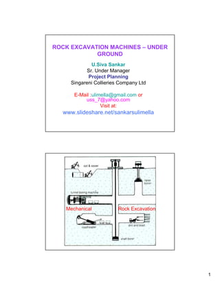
  • 1. ROCK EXCAVATION MACHINES – UNDER GROUND U.Siva Sankar Sr. Under Manager Project Planning Singareni Collieries Company Ltd E-Mail :ulimella@gmail.com or uss_7@yahoo.com Visit at: www.slideshare.net/sankarsulimella Mechanical Rock Excavation 1
  • 2. Mechanical Excavation Systems Different mechanical excavation systems, like machines with; Teeth (Dozer, Shovel, Scraper, Bucket wheel excavator, Bucket chain excavator) Ripping tool (Coal Plough, ripper, rock breaker), Pick mounted rotary cutting head/drum (Roadheader, Shearer, Continuous miner, Surface miner) Disc cutters and button bits (rock drill, Mobile tunnel miner, Tunnel boring machine) Auger tool (Continuous Auger Miner, Surface Auger Miner) Application of Mechanical Systems Under Ground: Continuous Miners, Bolter miners, Auger Miners and shearers for coal or soft nonmetalics Boom type miners (road headers in soft to medium hard rocks) Rapid excavation equipment (Mobile tunnel miners,Tunner borers, raise borers, and shaft sinking rigs) for soft to medium hard and hard rocks) Surface: Rippers for very compact soil, coal, and weathered or soft rock Bucket wheel and cutting head excavators for soil or coal Augers and highwall miners for coal Mechanical dredges for placers and soil Classification of Underground mechanical excavator by rock type Hard rock Soft rock 1.Roadheader 1.Roadheader 2.TBM 2.Continuous Miner 3.Mobile Miner 3.Shearer 4.Raise Borer Comparison of mechanical excavation with drill and blast systems Advantages Disadvantages • Generally gives more rapid advance than • Cannot excavate very hard rock blasting in soft to medium-hard rock. • High capital cost • Fewer unit operations • Require specialist maintenance • Smoother excavation profiles • Not as flexible • No blasting damage to surrounding rock • Inherently safer 2
  • 3. Parameters influencing applicability of mechanical miners The decision to introduce a mechanical miner is generally based on the predicted performance of the selected machine in the given geological and operational conditions. Since it is usually not possible to change the geological conditions, a thorough study of the geological and geotechnical parameters (rock mass and intact rock properties) at the feasibility and planning stages should be carried out to match the machine and operational parameters to the geological conditions. Machine considerations The general technical requirements of excavation machines, in addition to safety and economy, are selective mining ability, flexibility, mobility and hard and abrasive rock-cutting ability. Selective mining ability is the ability to cut selectively in mixed face conditions so that the mineral can be excavated separately, reducing dilution. Mobility means easy relocation of machines from one face to another, when necessary. Flexibility means easy adaptability to changing operational conditions, such as face cross-section shape (horseshoe, rectangular, circular, etc.), gradient, turning radius and unevenness of the floor. Machine considerations Hard and abrasive rock-cutting ability is the most important limiting factor on the performance of mechanical miners; applications show that strength, texture, etc., of the geological environment are the basic input parameters for the selection of mechanical miners and performance prediction. the most efficient type of tool in hard and abrasive rock. Geological and geotechnical considerations Rock mass features (such as joint sets, bedding planes, foliation, hydro geological conditions, deposit geometry, etc.) and intact rock properties (such as cuttability, abrasiveness etc). Operational considerations Mine layouts and development drivages are planned in accordance with the mining method, which is selected on the basis of orebody shape and dimensions and other deposit characteristics. For reliable, economic operation the characteristics and layout features of a mechanical miner should reflect whether it is to be used for the excavation of drifts or for ore/mineral. The layout might be modified for a particular mechanical miner if necessary. The back-up equipment (such as muck transportation, support, etc.) selected for a new mine must be chosen to be compatible with the mechanical miner. In an existing mining operation, however, the machine might be selected on the basis of the equipment already in use. 3
  • 4. Main influencing parameters for excavation Rock Rock composition Abrasivity (equivalent quartz content) Matrix Density (porosity/dry gross density) Strength: compressive-tensile-shear Destruction energy Post-failure behaviour Main influencing parameters for excavation Rock mass Joint structure: spacing, roughness, orientation Anisotropy: orientation, formation Primary stress conditions Weathering: type and degree Hydrothermal decomposition 4
  • 5. Compressive strength Density Abrasivity Discontinuities Moisture content Insitu stress condition Other Material properties 5
  • 6. CM- Continuous Miner, MTM- Mobile Tunnel Miner, TBM- Tunnel Boring Machine Abrasivity of rock ■ Definition: Abrasivity describes the behaviour of rock with regard to its „grinding“ effect on metal surfaces, predominantly picks. Abrasivity is influenced by Rock type and composition Content of hard minerals (quartz, phyrite, hard silicates) Grain size of hard minerals Intergranular bond 6
  • 8. 8
  • 9. Excavatability Index: N= Excavatability index Ms= Mass Strength number RQD= Rock Quality Designation Jn= Joint set number Js= relative ground structure number Jr= Joint roughness number Ja= joint alteration number 9
  • 10. Table: Mass Strength Number (MS) of rocks Fig: Joint Set Number (JN) for Rocks Fig: Relative ground structure (JS) of rocks Fig: Joint Roughness Number (Jr) for Rocks 10
  • 11. Fig: Joint Alteration Number (Ja) for Rocks Assessment of Cuttability and excavation Index (Kirsten,1982) Road Header: Roadheaders are the most widely used underground partial-face excavation machines for low to medium strength rocks. They are used for both development and production in soft rock mining industry (i.e. main haulage drifts, roadways, cross-cuts, etc.) particularly in coal, sedimentary rocks, industrial minerals and evaporitic rocks. In civil construction, they find extensive use for excavation of tunnels (railway, roadway, sewer, diversion tunnels, etc.) in soft ground conditions, as well as for enlargement and rehabilitation of various underground structures. Their ability to excavate almost any profile opening also makes them very attractive to those mining and civil construction projects where various opening sizes and profiles need to be constructed. "Roadheading" machines with a cutter head designed to excavate stone rather than coal instead of drilling and blasting. This gives a more continuous process and should give a good drift profile. The use is limited by the grades involved (maximum 1in 4 (140) and the hardness of the material to be cut (maximum 60-150 MPa UCS). 11
  • 12. In addition to their high mobility and versatility, roadheaders are generally low capital cost systems compared to the most other mechanical excavators. Because of higher cutting power density due to a small cutting drum, they offer the capability to excavate rocks harder and more abrasive than their counterparts, such as the continuous miners and borers. Roadheaders were first developed for mechanical excavation of coal in the early 50s. The major improvements achieved in the last 50 years consist of steadily increased machine weight, size and cutterhead power, improved design of boom, muck pick up and loading system, more efficient cutterhead design, metallurgical developments in cutting bits, advances in hydraulic and electrical systems and more widespread use of automation and remote control features. All these have led to drastic enhancements in machine cutting capabilities, system availability and the service life. Machine weights have reached from 17 tons up to 120 tons providing more stable and stiffer (less vibration, less maintenance) platforms from which higher thrust forces can be generated for attacking harder rock formations. The cutterhead power has increased significantly from 37 kW approaching to 500 kW to allow for higher torque capacities. Modern machines have the ability to cut cross-sections over 100 m2 from a stationary point. In comparison to drill and blast methods, the main advantages of roadheaders are: One machine is capable of cutting, loading and assisting in the erection of supports. Compared with conventional driving, a greater advance per manshift is obtained. Roof control is improved since the roof and sides of the roadway are not shattered by shotfiring. The machine is very stable, easily controlled and capable of cutting a large variety of roadway sections and sizes. It is safer since the men are near to the unsupported strata only during the erection of supports. 12
  • 13. Classification of Boom Type road Header: Generation: Weight (Tonnes) Compressive Strength of Generation Rock to be cut (MPa) 1st (1960) 9 40 2nd (1970) 22 to 37 85 3rd (1976) 45 to 70 100 4th (2000) 120 100 to 160 Weight: Tucker (1985) classified roadheaders according to weight as: Class Weight - Light Duty; weight up to 30 t, cutting capabilities up to 70 0 <20 t MPa I 20-30 t - Medium Duty; weight between 34 to 45 t, cutting capabilities II 30-50 t up to 100 MPa III 50-75 t - Heavy Duty; weight over 45 t, cutting capabilities up to 150 IV >75 t MPa Atlas Copco – Eickhoff established the following classification according to weight (Schneider, 1988); Classification of Boom Type road Header: Neil et. al (1994) refer roadheaders as small size up to 30 t, midsize between 30 to 70 t and large size between 70 to120 t. Cutting Action of heads: Milling type or Borer Type (axial head), and Ripping Type (Transverse head) Fig: Cutting action of roadheaders a. Ripping type, b. milling type 13
  • 14. Borer type Roadheader Borer type Roadheader 14
  • 15. Borer type Roadheader (Side view) Borer type Roadheader 15
  • 16. Ripper type Roadheader Ripper type Roadheader 16
  • 17. Fig: Double head or twin Boom Roadheader Cutting tools on Roadheader Radial picks are generally suitable for cutting soft to medium hard rocks and coal. Forward attack picks are also termed tangential picks, together with point attack picks due to the orientation of their tool axis. Such picks can also be used for cutting soft to medium hard rocks. Point attack picks, also known as pencil point tools, have been increasingly employed in medium to hard rock cutting and become an inevitable tool on medium and heavy duty roadheaders. 17
  • 18. Table; Factors influencing Cutting performance Fig. Comparison of cutting performance (Gehring, 1989) Cutting Mechanism in transverse head Roadheaders: Pick spacings around the cutting head are defined as line spacing (SL) and circumferential spacing (Cs) as shown in Fig. Line spacing is the distance between the cutting lines along the length of the cutting head and depends mainly on the depth of cut and cuttability of material being cut. Circumferential pick spacing is the angular distance between the picks measured perpendicular to the axis of rotation, which is mainly related to the angle of wrap, head diameter, line spacing, total number of picks, tool-holder size and additional space required for water sprays. Fig. Line and circumferential spacings on a cutting head. Fig: RH Cutting Action 18
  • 19. Fig. Lacing patterns of the first (unequal) and the second (equal) cutting heads. Fig. Breakout patterns of the experimental cutting heads. Manufacturing of equal spacing circumferential picks is not possible due to overlap of cutter picks. The performance of equal spaced picks is good in terms of breakout, vibration studies, but overall performance is not as good as unequal patterns. Pick consumption rate (pick/solid bank m3) varies from 0.049 to 0.044. If the rock is very abrasive or the pick consumption rate is more than 1 pick/m3, then roadheader excavation usually becomes uneconomical due to frequent bit changes coupled with increased vibration and maintenance costs. 19
  • 20. Continuous miner is a mining machine that produces a constant flow of ore from the working face of the mine. The machine continuously extracts as it is loading coal with a cutting steel drum and conveyor system. The continuous miner has been available in some form since the late 1800s. The first machine to resemble a continuous miner was known as the English Channel Machine. Continuous Miners Though there are many variations in design, continuous miners mostly consist of five main elements: A central body to carry all other components mounted on some type of drive mechanism to provide mobility (most commonly caterpillar tracks). A "cutting head" usually rotating drum(s) and/or chains with cutting picks attached A loading mechanism to pick up cut coal and deliver it into the central part of the machine A conveying system, usually a chain conveyor running in a steel trough from front to rear of the miner A rear jib section capable of a degree of vertical and horizontal movement to enable the coal to be delivered into a transport or loaded at a desired point. Continuous Miners 20
  • 21. Continuous Miners For extraction of hard rocks, continuous miner is designed to have both Ripperveyor cutter head and chainless cutter head. The diameter of chainless cutter head is less than that of Ripperveyor Continuous Miner Rate of drivage –50 meters/day Production –1500 Tonnes/day For seams of 1 in 5 gradient and flatter Thickness of 3.0 m to 4.0 m 21
  • 22. Continuous Miner Some continuous miners (at one time almost all) could not cut the full roadway width in one pass but had to be moved backwards and forwards and from side to side in order to cut the full profile. This often results in a very rough rib line (bad for stability and ventilation flow) and delays the ability to install support into/under freshly exposed roof for a period. The advantages of the ability to cut the full profile in one pass was recognized early, but was not easy to achieve. Cutting forward in a straight line could be readily accommodated, but it is necessary to be able to turn corners, mostly at right angles, and to be able to retreat the cutting machine from one roadway to relocate at frequent intervals. These factors have proved major stumbling blocks to many developments. In machines which covered the full face, steering in the vertical plane could also be a major difficulty. 22
  • 23. The "ideal" continuous miner would: Be able to cut the full face in one pass Be easily moveable between locations without dismantling parts Be able to excavate right angle turns with a minimum radius Have roof and rib bolters fixed to the machine in a location where each row of the designed support pattern can be installed without moving the miner and be installed close to the cut face if necessary Have adequate space alongside to allow good ventilation of the face area for efficient removal of gas and dust. Fig: Mining of Steep seams with roadheader and miller head (drum-type) miners Overview of Continuous Miner machine Manufacturers 23
  • 24. Overview of Continuous Miner machine types vs. Operation heights Lacing pattern on CM Drums Fig: Continuous drum with pick boxes The arrangement of picks on the vanes is called a lacing pattern. CM drum(10) comprises a cylindrical body(11) having an outer cylindrical surface(12). Extending from the surface are start vanes with each vane extending angularly and longitudinally w.r.t. longitudinal axis of the drum. at the drum end there is clearance ring vane up on the picks are positioned On each vane number of picks are placed, each pick having leading, trailing and side faces Upon rotation each pick follows cutting path with adjacent picks at a spacing of 30 to 100mm. 24
  • 25. Fig: Pick Lacing Pattern on Continuous Miner drum for Coal 25,26- End Rings, 27 Left Web Section, 29 Right web section 28 central web section Fig: Pick Lacing Pattern on Continuous Miner drum for Stone or Hard rocks 25
  • 26. Fig: Pick Lacing Pattern on Continuous Miner drum The picks are placed on each vane at an attack angle of between 400 to 500. The vanes extend angularly about at an angle 100 to 300 The spacing between picks is 50mm to 90mm on drums used for coal and 40 to 50mm on drums used for hard rock cutting. 26
  • 27. CM SUMPING SEQUENCE 1 CM SUMPING SEQUENCE 1 27
  • 28. CM SUMPING SEQUENCE 1 CM SUMPING SEQUENCE 2 28
  • 29. CM SUMPING SEQUENCE 3 CM SUMPING SEQUENCE 4 29
  • 30. CM SUMPING SEQUENCE 5 CM SUMPING SEQUENCE 6 30
  • 31. CM SUMPING SEQUENCE 7 CM SUMPING SEQUENCE 8 31
  • 32. CM SUMPING SEQUENCE 9 CM SUMPING SEQUENCE 10 32
  • 33. CM SUMPING SEQUENCE 11 CM SUMPING SEQUENCE 12 33
  • 34. CM SUMPING AND SHEAR SEQUENCE SD SH 1 CM SUMPING AND SHEAR SEQUENCE SD SH 1 2 34
  • 35. CM SUMPING AND SHEAR SEQUENCE SD SH 1 2 3 CM SUMPING AND SHEAR SEQUENCE SD SH 1 2 3 4 35
  • 36. CM SUMPING AND SHEAR SEQUENCE SD SH 1 2 3 4 5 CM SUMPING AND SHEAR SEQUENCE SD SH 1 2 3 4 5 6 36
  • 37. CM SUMPING AND SHEAR SEQUENCE SD SH 1 2 3 4 5 6 7 CM SUMPING AND SHEAR SEQUENCE 8 9 SD SH 1 2 3 4 5 6 7 37
  • 38. Auger Mining: The potential for underground coal production from drilling or augering machines has been recognized since at least the 1940s. These machines could bore into the virgin coal from stabilized entries and provide access to otherwise sterilized coal reserves. Auger drills mounted with cutterheads cut and fracture through both overburden and coal, operating very similar to a drill machine. The cutting action of an auger differs from other coal cutting machines, such as continuous miners, in that it exploits the lower tensile strength of coal rather than overcoming the comparatively high compressive strength of coal. Therefore, auger drills are able to generate a greater amount of power in cutting coal than a continuous miner. This makes augers more efficient in terms of the power needed to cut the coal. There are Thin seam auger miner for extraction in thin UG seams and Surface auger Miner for extraction of seams from highwall of open pit mines Fig: Auger Miner for Thin seam extraction 38
  • 39. Auger performance is principally governed by two main factors; machine power and cutter head diameter. The greater the power available the deeper the penetration and the higher the mining rate, for the same machine configuration. The larger the diameter of the cutter head the greater the rate of production per metre of hole advance and hence the higher the mining rate. Thin seam miner (TSM) is actually a type of continuous miner that can cut seams from 0.6m to1.2m height and up to 1.5 m high into a coal seam situated under a highwall in surface mines Augers drills used in surface mining can range from 18 to 61 m in length to two to seven feet (0.6 to 2.1 m) in diameter. The cutter head on the auger bores a number of openings into the seam, similar to how a wood drill produces wood shavings. The coal is then extracted and transported up to the surface via the spiral action of flights. Additional auger lengths or flights can then be added as the cutter head penetrates and drives deeper down into the bored hole Auger mining is a low-cost method of recovering coal from horizontal or slightly pitched seams exposed through geological erosion. The practice of auger mining is reserved primarily for extracting coal at depths of up to 1,000 feet (305 m). One of the drawbacks is that once the cutter head enters the coal seam, the operator is unable to view the cutting action directly and must rely more on a sense of feel for the machine to determine potential problems. Auger Advantages Proven ability to mine a cleaner coal product Proven selective mining capabilities Extremely low ground pressure Heavy duty construction for hard cutting Remote control capabilities Proven low cost solutions for Ultra Thin Seam Mining 39
  • 40. FiG: Surface Auger Mining High wall Mining Technology – Auger Type • Consisting of single or dual cutting heads with coal being cleared by spiraled flights, creating circular entries 40
  • 41. High wall Mining Technology – Auger Type DUAL HEAD AUGER Fig: Auger Cutter head and Auger Flights 41
  • 42. Coal Ploughes Essentially a plough is a large mass of steel, usually of a more or less triangular shape when viewed from the coal face or goaf sides, fitted with large "picks" (more like small agricultural plough blade tips) angled from the steel body towards the coal face. The plough height is the working height in the seam being mined (possibly a bit lower if the coal tops can be guaranteed to fall once the coal below is cut. These "picks" act in a fashion similar to chisels and break a narrow web of coal off the face (of the order of 300-400mm thick). In most cases there are no moving parts on a coal plough. The plough itself is mounted on the front of the AFC and is pushed into the face by push cylinders mounted in the supports. The plough has an endless chain haulage attached to the rear, and is driven through sprockets on electric drive(s) at the face end(s). Coal Ploughes The main advantages of ploughs compared to shearers are: Cheap Simple (no moving parts on the cutting machine itself) Relatively low dust make Able to keep exposed roof area very small (but a large number of chock movements would be required to maintain this) Though only a small web is taken, in the right conditions production rates can be comparable to a shearer as the plough is operated at a relatively fast speed along the face. Some disadvantages are: Cutting height is fixed Ability to cut stone is limited With increasing cutting height, machine stability becomes more problematic Grading can only be done using the AFC angle There are safety implications with an exposed chain haulage. 42
  • 43. Plow Systems Plow systems are intended for coal mining in flat and inclined seams with the inclination up to 40° with coal hardness up to 40 MPa in seams with the height range from 0.6m to 1.8m In dependence on seam thickness and mining conditions plow systems can be operated either with powered roof support or with individual hydraulic support (pit props) Mining Machines Division Plow Systems BASE PLATE PLOW The plow system using atypical pan line with plow guide and plow chain on the goaf side. Advantages • It is very suitable for extremely low seams from 0.6m. • Easy access to a tow chain of the plow. • High safety while handling with a tow chain also in inclinations. Disadvantages • Losses due to friction of the plow body bottom plate on the floor. 43
  • 44. Plow Systems SLIDING PLOW The plow system using atypical pan line with plow guide and plow chain on the face side. Advantages • It is intended for seams from 0.9m to 1.8m. • Well controllable even when the floor is rolling. • Low losses due to friction by a plow body. Disadvantages • It is unsuitable for seams less than 0.9m. • Not easy access to a tow chain of the plow. • Difficult and dangerous while handling with a tow chain. Plow Systems Advantages Disadvantages • It is very suitable for extremely low seams from 0.6m. • Losses due to friction of the plow body • Easy access to a tow chain of the plow. bottom plate on the floor. • High safety while handling with a tow chain also in inclinations. BASE PLATE PLOW The plow system using atypical pan line with plow guide and plow chain on the goaf side. 44
  • 45. Plow Systems Advantages Disadvantages • It is intended for seams from 0.9m to 1.8m. • It is unsuitable for seams less than • Well controllable even when the floor is 0.9m. rolling. • Not easy access to a tow chain of the • Low losses due to friction by a plow body. plow. • Difficult and dangerous while handling with a tow chain. SLIDING PLOW The plow system using atypical pan line with plow guide and plow chain on the face side. Shearers A shearer consists of a machine body containing electric motors, hydraulic equipment and controls which is mounted over the AFC. Horizontal cutting drums are mounted on the face side of the machine, laced with cutting picks and rotating in a plane parallel to the face. If the AFC is pushed towards the face as the cutting drums are rotated and the shearer travels along the face, it is able to cut into the face for the full web width, moving along a snake in the AFC. This is known as "sumping in". Once fully into the web, the shearer can advance the full length of the face cutting out the web. The snake can also be reversed to cut the wedge shaped portion of coal left while sumping in. 45
  • 46. Shearer Large diameter drums could have a pre-cutter to aid in rib face control on the longwall face. Pre_Cutting Fig: Shearer Drums with Radial and Point attack picks Fig: Side view of Shearer drum 46
  • 47. Fig; Positioning picks on shearer drums Positioning picks on shearer drums Shearer drums consist of several spiral vanes and a backplate welded on a hollow drum shell. The spiral vanes serve for cutting and loading, while the backplate is mainly used for corner cutting at the face side to relieve the cutting action of the vane picks. The linear advance of a shearer drum per entire revolution is produced by the combined cutting actions of the vanes. Spiral vanes and the backplate provide space for the picks to be mounted on drums. Spiral vanes or cutting sequences on shearer drums are also known as ‘starts’, and the number of starts equal that of the spiral vanes. The total number of starts on a shearer drum varies(3,4,6) depending on the shearer drum design Picks can be classified according to their tilt angles and positions on the cutting head. The tilt angle is the angle between the pick axis and a plane perpendicular to the axis of cutting head rotation (Figure a). Picks, with their axes perpendicular to the axis of cutting head rotation, are named traversing or arcing picks, while those mounted on the region closer to the nose section of the cutting head, with individual tilt angles, are termed gauge picks. Sumping picks are placed on the nose section of the cutting head with their axes parallel to the axis of rotation of the cutting head. The last gauge pick on the face side of the cutting head is known as the corner cutting pick. 47
  • 48. Fig. Pick positioning on a shearer drum: (a) profile view of the drum (b) lacing of spiral and clearance ring picks Positioning picks on shearer drums A modern shearer drum also has three groups of picks cutting the coal seam while it rotates and transfers coal particles from the face onto the armoured face conveyor. The first group of picks that cuts most of the coal-seam, which are mounted on spiral vanes and correspond to the traversing picks on the roadheader cutting heads, are named vane picks. The second group of picks mounted on the backplate section of the shearer drum, and corresponding to the gauge picks on the roadheader cutting heads, are termed clearance ring picks. Today’s shearer drums also have some sumping picks mounted on the outer face of the clearance ring to provide extra protection for the drum The arrangement of clearance ring picks on the shearer drum was reported to be more complicated than that of vane picks The forces required to cut the coal at a certain depth by a clearance ring pick were reported to be two to ten times higher than the forces needed to cut the coal at the same depth by a vane pick More the wear of the clearance ring picks than others 48
  • 49. Mobile Tunnel Miner (MTM) Characteristics and advantages Especially developed for hard rock tunneling and mining This method allows for any shape of tunnel (rectangular, horse-shoe or circular) The technology requires less cutting force than a normal TBM Combines the flexibility of a roadheader and the power of a TBM Mobile Tunnel Miner (MTM) MTM is able to excavate any shape of tunnel (rectangular, horse-shoe or circular) MTM works with the “Under cutting Technique” requiring less cutting forces than with a normal hard rock TBM. The cutting principle with under cutting disc cutters is highly efficient as it overcomes the lower tensile strength of the rock instead of higher compressive strength. The machine is equipped with a crawler unit and a gripper system. The unit allows the MTM to move without using the crawler. The MTM is equipped with 3,4 or 8 arms depending on the size of the tunnel. The muck is transported to the rear of the machine, similar to roadheader Fig: Schematic drawing of the cutting technique 49
  • 50. Tunnel Boring Machine (TBM) TBM is a full face excavator which cuts rock by means of disc cutters mounted on a circular revolving cutting head (figure 7.5). The following design features enable it to cut stronger rock than any other type of mechanical excavator. Large mass Hydraulic stabilising jacks High cutting force provided by hydraulic thrust rams Cutting discs for rock breakage by indentation Because of the size and weight of the typical TBM, they are suitable only for the excavation of long straight drivages such as civil engineering tunnels. Tunnel Boring Machine (TBM) TBM provides a good, circular profile which is good for stability and ventilation but usually requires a false floor to be laid to create a flat floor for travel. Limited by grades involved and grade control can be problematic is some strata conditions. Not suitable for other than very gradual changes of direction (typically minimum 500m turning radius although tighter radius machines can be designed and utilized). Unlike drill and blast or roadheading methods, tunnel boring machines do not have the capability to readily vary the dimension of the excavation nor are they suitable in varying ground conditions. Disadvantages of TBMs High capital cost (several million dollars) Can only cut circular section Large turning radius (100 m) Time-consuming to install Minimum tunnel length of 2 km required to justify installation 50
  • 51. Wide choice of TBMs for rock tunneling with diameter > 14m for different ground conditions Open or Gripper type for hard ground Single shield – hard ground Double shield – hard ground EPB (Earth Pressure Balance Machines) – Soft ground, pressure< 7 bar Slurry and mix-shield – Soft ground with very high water pressure and large amounts of ground water Fig: Gripper TBM The largest diameter TBM, at 15.43 m, was built by Herrenknecht AG for a recent project in Shanghai, China. The machine was built to bore through soft ground including sand and clay. The largest diameter hard rock TBM, at 14.4 m, was manufactured by The Robbins Company for Canada's Niagara Tunnel Project. 1 Cutterhead 4 Anchor Drilling Devices 2 Cutterhead Support 5 Wire Mesh Erector 3 Ring Erector 5 2 1 4 3 Fig: Gripper TBM 51
  • 52. A TBM breaks rock with disc cutters mounted on the rotating cutter-head in such a pattern that they roll against the rock of the tunnel face in a series of concentric circular grooves or kerfs. The cutting force is produced by powerful hydraulic thrust rams. Each disc cutter is free to rotate within its mounting. The high cutting forces required to break strong rock types produce equally high reaction forces on the machine. To maintain contact with the rock and to maintain the optimum spacing between cutting grooves, the machine is held stable by a combination of its great mass and by hydraulic jacks (grippers) acting against the side of the tunnel. Broken rock is gathered from the floor by scoops mounted around the perimeter of the cutting head and discharged at the crown of the cutter head onto a belt conveyor that runs through the center of the machine Cutter head Grippers Conveyor 1. Start boring stroke 2. End Main boring body stroke 3. Start reset stroke Invert Front Thrust Rear Main scraper lift leg cylinder lift leg motors 4. End Fig: Cutting cycle of Atlas Copco TBM reset stroke Fig: Hydraulic jacks holding a TBM in place. 1. Cutter head 2. Front shield 3. Main beam 4. Gripper trolley 5. thrust cylinders 6. Belt conveyor 7. Ring beam erector structure 8. Shortcret Fig: Gripper Shield 52
  • 53. All types of hard rock TBMs excavate rock using disc cutters mounted in the cutter head. The disc cutters create compressive stress fractures in the rock, causing it to chip away from the rock in front of the machine, called the tunnel face. The excavated rock, known as muck, is transferred through openings in the cutter head to a belt conveyor, where it runs through the machine to a system of conveyors or muck cars for removal from the tunnel. Cutter head of soft rock TBM does not use disc cutters only, but instead a combination of tungsten carbide cutting bits, carbide disc cutters, and/or hard rock disc cutters. Fig. Disc type cutter. Fig. (a) Kerf cutter (b) Pineapple cutter. Different Cutter Heads - TBMs 53
  • 54. 54
  • 55. Single Shield TBM 1.Cutter head 2.Shield 3.Belt conveyor 4.Excavated material removal trolley 55
  • 56. Double Shield TBM 1. Cutter head 2. Shields 2a - Front shield 2b - Double shield 2c - Rear shield and gripper Belt conveyor Excavated material removal trolley 56
  • 58. Fig: Schematic representation of EPBM Fig: Types of Cutting face of EPBMs Schematic representation of a slurry type shield machine Cutting head sketch of slurry type shield 58
  • 59. Types of cutting face of slurry type shield 59