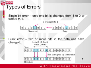
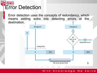
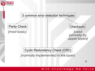
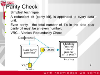
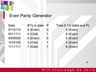
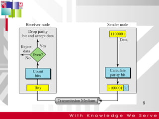
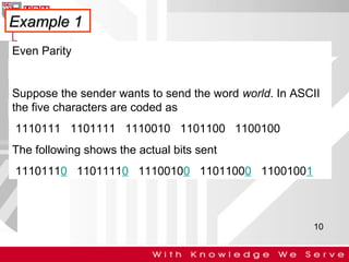
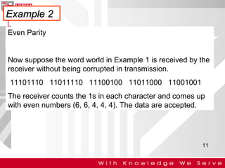
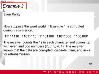
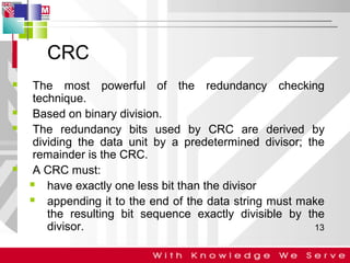
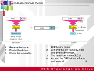
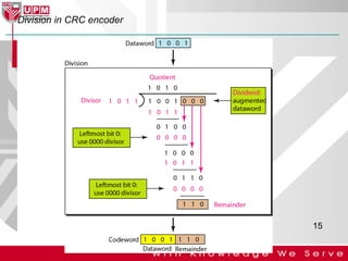
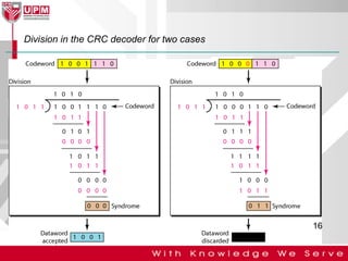
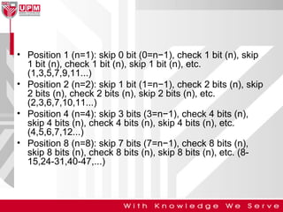
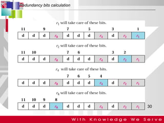
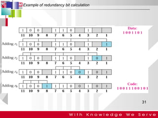
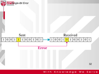
Computer Network and
Communication
SKR 3200

1
Learning Outcome
• Show how to detect an error (P2)
• Show how the errors being corrected (P2)
• Explain the method being used to detect
and corrected the errors (A3)
Contents
• Types of Error
– Single bit error
– Burst error
• Error Detection
– Parity Check
– CRC
– Checksum
• Error Correction
– Hamming Code
3
Types of Errors


Single bit error – only one bit is changed from 1 to 0 or
from 0 to 1.



Burst error – two or more bits in the data unit have
changed.

4
Error Detection


Error detection uses the concepts of redundancy, which
means adding extra bits detecting errors at the
destination.

5
3 common error detection techniques
Parity Check

Checksum

(most basic)

(used
primarily by
upper layers)

Cyclic Redundancy Check (CRC)
(normally implemented in link layer)
6
Parity Check







Simplest technique.
A redundant bit (parity bit), is appended to every data
unit.
Even parity - the total number of 1's in the data plus
parity bit must be an even number.
VRC – Vertical Redundancy Check

7
Even Parity Generator
Data
0110110
0011111
0000000
1010100
1111111

#1's in data
4 (Even)
5 (Odd)
0 (Even)
3 (Odd)
7 (Odd)

P
0
1
0
1
1

Total # 1's (data and P)
4 (Even)
6 (Even)
0 (Even)
4 (Even)
8 (Even)

8
9
Example 1
Even Parity

Suppose the sender wants to send the word world. In ASCII
the five characters are coded as
1110111 1101111 1110010 1101100 1100100
The following shows the actual bits sent
11101110 11011110 11100100 11011000 11001001

10
Example 2
Even Parity

Now suppose the word world in Example 1 is received by the
receiver without being corrupted in transmission.
11101110 11011110 11100100 11011000 11001001
The receiver counts the 1s in each character and comes up
with even numbers (6, 6, 4, 4, 4). The data are accepted.

11
Example 3
Even Parity

Now suppose the word world in Example 1 is corrupted
during transmission.
11111110 11011110 11101100 11011000 11001001
The receiver counts the 1s in each character and comes up
with even and odd numbers (7, 6, 5, 4, 4). The receiver
knows that the data are corrupted, discards them, and asks
for retransmission.
12
CRC







The most powerful of the redundancy checking
technique.
Based on binary division.
The redundancy bits used by CRC are derived by
dividing the data unit by a predetermined divisor; the
remainder is the CRC.
A CRC must:

have exactly one less bit than the divisor

appending it to the end of the data string must make
the resulting bit sequence exactly divisible by the
divisor.
13
CRC generator and checker

1.
2.
3.

Receive the frame.
Divide it by divisor.
Check the remainder.

1.
2.
3.
4.

Get the raw frame.
Left shift the raw frame by n bits
and divide it by divisor.
The remainder is the CRC bit.
Append the CRC bit to the frame
and transmit.
14
Division in CRC encoder

15
Division in the CRC decoder for two cases

16




CRC generator – at the sending node.
CRC checker – at the receiving node.
Polynomial:

The CRC generator (the divisor) is most often
represented as an algebraic polynomial.

e.g.

17
A polynomial representing a divisor

18
Standard polynomials
Name

Polynomial

Application

CRC-8

x8 + x2 + x + 1

ATM header

CRC-10

x10 + x9 + x5 + x4 + x 2 + 1

ATM AAL

ITU-16

x16 + x12 + x5 + 1

HDLC

ITU-32

x32 + x26 + x23 + x22 + x16 + x12 + x11 + x10 + x8 +
x7 + x5 + x4 + x2 + x + 1

LANs

19
Checksum







The error detection used by the higher-layer
protocols.
Check generator – in the sending node
Checksum checker – at receiving node
SFD – Start Frame Delimiter
FCS – Frame Check Sequence

Ethernet frame

20
Data unit and checksum

21
Example 6
Suppose the following block of 16 bits is to be sent using a
checksum of 8 bits.
10101001 00111001
The numbers are added using one’s complement
10101001

Sum
Checksum

00111001
-----------11100010
00011101

The pattern sent is

10101001 00111001 00011101

22
Example 7
Now suppose the receiver receives the pattern sent in
Example 6 and there is no error.
10101001 00111001 00011101
When the receiver adds the three sections, it will get all 1s,
which, after complementing, is all 0s and shows that there is
no error.
10101001
00111001
00011101
-----------Sum

11111111

Complement

00000000 means that the pattern is OK.

23
Example 8
Now suppose there is a burst error of length 5 that affects 4
bits.
Original data

10101001 00111001 00011101

Corrupted data

10101111 11111001 00011101

When the receiver adds the three sections, it gets
10101111
11111001
00011101
Partial Sum

1 11000101

Carry
Sum
Complement

1
11000110
00111001

the pattern is corrupted.

24
Error Correction
Hamming Code

Focus on a simple case: Single-Bit Error
Correction

Use the relationship between data and
redundancy bits

Developed by Richard Hamming

25
Data and redundancy bits
Number of
data bits
m

Number of
redundancy bits
r

Total
bits
m+r

1

2

3

2

3

5

3

3

6

4

3

7

5

4

9

6

4

10

7

4

11
26
Positions of redundancy bits in Hamming code (11,7)

* Check bits occupy positions that are powers of 2
27
• All bit positions that are powers of 2 are used as
parity bits. (positions 1, 2, 4, 8…)
• All other bit positions are for the data to be
encoded. (positions 3, 5, 6, 7, 9, 10, 11…)
• Each parity bit calculates the parity for some of
the bits in the code word. The position of the
parity bit determines the sequence of bits that it
alternately checks and skips.
• General rule for position n: skip n−1 bits, check n
bits, skip n bits, check n bits...

28
• Position 1 (n=1): skip 0 bit (0=n−1), check 1 bit (n), skip
1 bit (n), check 1 bit (n), skip 1 bit (n), etc.
(1,3,5,7,9,11...)
• Position 2 (n=2): skip 1 bit (1=n−1), check 2 bits (n), skip
2 bits (n), check 2 bits (n), skip 2 bits (n), etc.
(2,3,6,7,10,11...)
• Position 4 (n=4): skip 3 bits (3=n−1), check 4 bits (n),
skip 4 bits (n), check 4 bits (n), skip 4 bits (n), etc.
(4,5,6,7,12...)
• Position 8 (n=8): skip 7 bits (7=n−1), check 8 bits (n),
skip 8 bits (n), check 8 bits (n), skip 8 bits (n), etc. (815,24-31,40-47,...)
Redundancy bits calculation

30
Example of redundancy bit calculation

31
Single-Bit Error

32
Error detection using Hamming code

Error
Detection

33

Skr+3200+chapter+3+(kweh)

  • 1.
  • 2.
    Learning Outcome • Showhow to detect an error (P2) • Show how the errors being corrected (P2) • Explain the method being used to detect and corrected the errors (A3)
  • 3.
    Contents • Types ofError – Single bit error – Burst error • Error Detection – Parity Check – CRC – Checksum • Error Correction – Hamming Code 3
  • 4.
    Types of Errors  Singlebit error – only one bit is changed from 1 to 0 or from 0 to 1.  Burst error – two or more bits in the data unit have changed. 4
  • 5.
    Error Detection  Error detectionuses the concepts of redundancy, which means adding extra bits detecting errors at the destination. 5
  • 6.
    3 common errordetection techniques Parity Check Checksum (most basic) (used primarily by upper layers) Cyclic Redundancy Check (CRC) (normally implemented in link layer) 6
  • 7.
    Parity Check     Simplest technique. Aredundant bit (parity bit), is appended to every data unit. Even parity - the total number of 1's in the data plus parity bit must be an even number. VRC – Vertical Redundancy Check 7
  • 8.
    Even Parity Generator Data 0110110 0011111 0000000 1010100 1111111 #1'sin data 4 (Even) 5 (Odd) 0 (Even) 3 (Odd) 7 (Odd) P 0 1 0 1 1 Total # 1's (data and P) 4 (Even) 6 (Even) 0 (Even) 4 (Even) 8 (Even) 8
  • 9.
  • 10.
    Example 1 Even Parity Supposethe sender wants to send the word world. In ASCII the five characters are coded as 1110111 1101111 1110010 1101100 1100100 The following shows the actual bits sent 11101110 11011110 11100100 11011000 11001001 10
  • 11.
    Example 2 Even Parity Nowsuppose the word world in Example 1 is received by the receiver without being corrupted in transmission. 11101110 11011110 11100100 11011000 11001001 The receiver counts the 1s in each character and comes up with even numbers (6, 6, 4, 4, 4). The data are accepted. 11
  • 12.
    Example 3 Even Parity Nowsuppose the word world in Example 1 is corrupted during transmission. 11111110 11011110 11101100 11011000 11001001 The receiver counts the 1s in each character and comes up with even and odd numbers (7, 6, 5, 4, 4). The receiver knows that the data are corrupted, discards them, and asks for retransmission. 12
  • 13.
    CRC     The most powerfulof the redundancy checking technique. Based on binary division. The redundancy bits used by CRC are derived by dividing the data unit by a predetermined divisor; the remainder is the CRC. A CRC must:  have exactly one less bit than the divisor  appending it to the end of the data string must make the resulting bit sequence exactly divisible by the divisor. 13
  • 14.
    CRC generator andchecker 1. 2. 3. Receive the frame. Divide it by divisor. Check the remainder. 1. 2. 3. 4. Get the raw frame. Left shift the raw frame by n bits and divide it by divisor. The remainder is the CRC bit. Append the CRC bit to the frame and transmit. 14
  • 15.
    Division in CRCencoder 15
  • 16.
    Division in theCRC decoder for two cases 16
  • 17.
       CRC generator –at the sending node. CRC checker – at the receiving node. Polynomial:  The CRC generator (the divisor) is most often represented as an algebraic polynomial.  e.g. 17
  • 18.
  • 19.
    Standard polynomials Name Polynomial Application CRC-8 x8 +x2 + x + 1 ATM header CRC-10 x10 + x9 + x5 + x4 + x 2 + 1 ATM AAL ITU-16 x16 + x12 + x5 + 1 HDLC ITU-32 x32 + x26 + x23 + x22 + x16 + x12 + x11 + x10 + x8 + x7 + x5 + x4 + x2 + x + 1 LANs 19
  • 20.
    Checksum      The error detectionused by the higher-layer protocols. Check generator – in the sending node Checksum checker – at receiving node SFD – Start Frame Delimiter FCS – Frame Check Sequence Ethernet frame 20
  • 21.
    Data unit andchecksum 21
  • 22.
    Example 6 Suppose thefollowing block of 16 bits is to be sent using a checksum of 8 bits. 10101001 00111001 The numbers are added using one’s complement 10101001 Sum Checksum 00111001 -----------11100010 00011101 The pattern sent is 10101001 00111001 00011101 22
  • 23.
    Example 7 Now supposethe receiver receives the pattern sent in Example 6 and there is no error. 10101001 00111001 00011101 When the receiver adds the three sections, it will get all 1s, which, after complementing, is all 0s and shows that there is no error. 10101001 00111001 00011101 -----------Sum 11111111 Complement 00000000 means that the pattern is OK. 23
  • 24.
    Example 8 Now supposethere is a burst error of length 5 that affects 4 bits. Original data 10101001 00111001 00011101 Corrupted data 10101111 11111001 00011101 When the receiver adds the three sections, it gets 10101111 11111001 00011101 Partial Sum 1 11000101 Carry Sum Complement 1 11000110 00111001 the pattern is corrupted. 24
  • 25.
    Error Correction Hamming Code  Focuson a simple case: Single-Bit Error Correction  Use the relationship between data and redundancy bits  Developed by Richard Hamming 25
  • 26.
    Data and redundancybits Number of data bits m Number of redundancy bits r Total bits m+r 1 2 3 2 3 5 3 3 6 4 3 7 5 4 9 6 4 10 7 4 11 26
  • 27.
    Positions of redundancybits in Hamming code (11,7) * Check bits occupy positions that are powers of 2 27
  • 28.
    • All bitpositions that are powers of 2 are used as parity bits. (positions 1, 2, 4, 8…) • All other bit positions are for the data to be encoded. (positions 3, 5, 6, 7, 9, 10, 11…) • Each parity bit calculates the parity for some of the bits in the code word. The position of the parity bit determines the sequence of bits that it alternately checks and skips. • General rule for position n: skip n−1 bits, check n bits, skip n bits, check n bits... 28
  • 29.
    • Position 1(n=1): skip 0 bit (0=n−1), check 1 bit (n), skip 1 bit (n), check 1 bit (n), skip 1 bit (n), etc. (1,3,5,7,9,11...) • Position 2 (n=2): skip 1 bit (1=n−1), check 2 bits (n), skip 2 bits (n), check 2 bits (n), skip 2 bits (n), etc. (2,3,6,7,10,11...) • Position 4 (n=4): skip 3 bits (3=n−1), check 4 bits (n), skip 4 bits (n), check 4 bits (n), skip 4 bits (n), etc. (4,5,6,7,12...) • Position 8 (n=8): skip 7 bits (7=n−1), check 8 bits (n), skip 8 bits (n), check 8 bits (n), skip 8 bits (n), etc. (815,24-31,40-47,...)
  • 30.
  • 31.
    Example of redundancybit calculation 31
  • 32.
  • 33.
    Error detection usingHamming code Error Detection 33