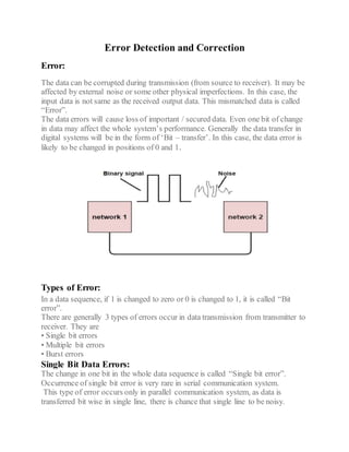
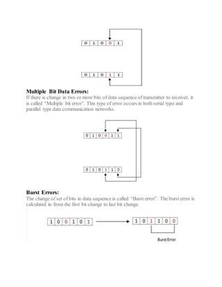
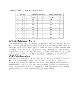
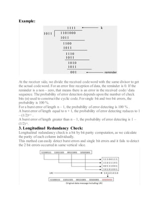
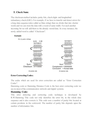
Error Detection and Correction
Error:
The data can be corrupted during transmission (from source to receiver). It may be
affected by external noise or some other physical imperfections. In this case, the
input data is not same as the received output data. This mismatched data is called
“Error”.
The data errors will cause loss of important / secured data. Even one bit of change
in data may affect the whole system’s performance. Generally the data transfer in
digital systems will be in the form of ‘Bit – transfer’. In this case, the data error is
likely to be changed in positions of 0 and 1.
Types of Error:
In a data sequence, if 1 is changed to zero or 0 is changed to 1, it is called “Bit
error”.
There are generally 3 types of errors occur in data transmission from transmitter to
receiver. They are
• Single bit errors
• Multiple bit errors
• Burst errors
Single Bit Data Errors:
The change in one bit in the whole data sequence is called “Single bit error”.
Occurrence of single bit error is very rare in serial communication system.
This type of error occurs only in parallel communication system, as data is
transferred bit wise in single line, there is chance that single line to be noisy.
Multiple Bit Data Errors:
If there is change in two or more bits of data sequence of transmitter to receiver, it
is called “Multiple bit error”. This type of error occurs in both serial type and
parallel type data communication networks.
Burst Errors:
The change of set of bits in data sequence is called “Burst error”. The burst error is
calculated in from the first bit change to last bit change.
Error Detecting Codes:
Error detection is the process ofdetecting the errors that are present in the data
transmitted from transmitter to receiver, in a communication system. We use some
redundancy codes to detect these errors, by adding to the data while it is
transmitted from source(transmitter). These codes are called “Error detecting
codes”.
Types of Error detection:
1. Parity Checking
2. Cyclic Redundancy Check (CRC)
3. Longitudinal Redundancy Check (LRC)
4. Check Sum
1. Parity Checking
Parity bit means nothing but an additional bit added to the data at the transmitter
before transmitting the data. Before adding the parity bit, number of 1’s or zeros is
calculated in the data. Based on this calculation of data an extra bit is added to the
actual information / data. The addition of parity bit to the data will result in the
change of data string size.
This means if we have an 8 bit data, then after adding a parity bit to the data binary
string it will become a 9 bit binary data string.
There is two types of parity bits in error detection, they are
 Even parity
 Odd parity
Even Parity:
 If the data has even number of 1’s, the parity bit is 0.
 Data is 10000001 -> parity bit 0
 Odd number of 1’s, the parity bit is 1.
 Data is 10010001 -> parity bit 1
Odd Parity:
 If the data has odd number of 1’s, the parity bit is 0.
 Data is 10011101 -> parity bit 0
 Even number of 1’s, the parity bit is 1.
 Data is 10010101 -> parity bit 1
Messages with evenparity and odd parity
2. Cyclic Redundancy Check
The codes used for cyclic redundancy check there by error detection are known as
CRC codes (Cyclic redundancy check codes).Cyclic redundancy-check codes are
shortened cyclic codes. These types of codes are used for error detection and
encoding. They are easily implemented using shift-registers with feedback
connections. That is why they are widely used for error detection on digital
communication. CRC codes will provide effective and high level of protection.
CRC Code Generation:
Based on the desired number of bit checks, we will add some zeros (0) to the actual
data. This new binary data sequence is divided by a new word of length n + 1,
where n is the number of check bits to be added . The reminder obtained as a result
of this modulo 2- division is added to the dividend bit sequence to form the cyclic
code. The generated codeword is completely divisible by the divisor that is used in
generation of code. This is transmitted through the transmitter.
Example:
At the receiver side, we divide the received codeword with the same divisor to get
the actual codeword. For an error free reception of data, the reminder is 0. If the
reminder is a non – zero, that means there is an error in the received code/ data
sequence. The probability of error detection depends upon the number of check
bits (n) used to constructthe cyclic code. Forsingle bit and two bit errors, the
probability is 100 %.
For a burst error of length n – 1, the probability of error detecting is 100 % .
A burst error of length equal to n + 1, the probability of error detecting reduces to 1
– (1/2)n-1 .
A burst error of length greater than n – 1, the probability of error detecting is 1 –
(1/2) n.
3. Longitudinal Redundancy Check:
Longitudinal redundancy check is a bit by bit parity computation, as we calculate
the parity of each column individually.
This method can easily detect burst errors and single bit errors and it fails to detect
the 2 bit errors occurred in same vertical slice.
5. Check Sum:
The checksum method includes parity bits, check digits and longitudinal
redundancy check (LRC). For example, if we have to transfer and detect errors for
a long data sequence (also called as Data string) then we divide that into shorter
words and we can store the data with a word of same width. For each another
incoming bit we will add them to the already stored data. At every instance, the
newly added word is called “Checksum”.
Error Correcting Codes:
The codes which are used for error correction are called as “Error Correction
Codes”.
Hamming code or Hamming Distance Code is the best error correcting code we
use in most of the communication network and digital systems.
Hamming Code:
This error detecting and correcting code technique is developed by
R.W.Hamming. This code not only identifies the error bit, in the whole data
sequence and it also corrects it. This code uses a number of parity bits located at
certain positions in the codeword. The number of parity bits depends upon the
number of information bits.
Example:
Encode the data 1101 in even parity, by using Hamming code.
Step 1
Calculate the required number of parity bits.
Let P = 2, then
2P = 22 = 4 and n + P + 1 = 4 + 2 + 1 = 7.
2 parity bits are not sufficient for 4 bit data.
So let’s try P = 3, then
2P = 23 = 8 and n + P + 1 = 4 + 3 + 1 = 8
Therefore 3 parity bits are sufficient for 4 bit data.
The total bits in the code word are 4 + 3 = 7
Step 2
Constructing bit location table
Step 3
Determine the parity bits.
For P1: 3, 5 and 7 bits are having three 1’s so for even parity, P1 = 1.
For P2: 3, 6 and 7 bits are having two 1’s so for even parity, P2 = 0.
For P3: 5, 6 and 7 bits are having two 1’s so for even parity, P3 = 0.
By entering / inserting the parity bits at their respective positions, codeword can be
formed and is transmitted. It is 1100101.
If the codeword has all zeros (ex: 0000000), then there is no error in Hamming
code.
Assignment No 1
Name:
M.FaisalYaqoob
Class:
4th
semesterBE (EE) (B)
Cms ID:
1186-2017
Subject:
Computer CommunicationNetwork
Submitted to:
Engr.Uzma Majeed

Error dectation and correction

  • 1.
    Error Detection andCorrection Error: The data can be corrupted during transmission (from source to receiver). It may be affected by external noise or some other physical imperfections. In this case, the input data is not same as the received output data. This mismatched data is called “Error”. The data errors will cause loss of important / secured data. Even one bit of change in data may affect the whole system’s performance. Generally the data transfer in digital systems will be in the form of ‘Bit – transfer’. In this case, the data error is likely to be changed in positions of 0 and 1. Types of Error: In a data sequence, if 1 is changed to zero or 0 is changed to 1, it is called “Bit error”. There are generally 3 types of errors occur in data transmission from transmitter to receiver. They are • Single bit errors • Multiple bit errors • Burst errors Single Bit Data Errors: The change in one bit in the whole data sequence is called “Single bit error”. Occurrence of single bit error is very rare in serial communication system. This type of error occurs only in parallel communication system, as data is transferred bit wise in single line, there is chance that single line to be noisy.
  • 2.
    Multiple Bit DataErrors: If there is change in two or more bits of data sequence of transmitter to receiver, it is called “Multiple bit error”. This type of error occurs in both serial type and parallel type data communication networks. Burst Errors: The change of set of bits in data sequence is called “Burst error”. The burst error is calculated in from the first bit change to last bit change.
  • 3.
    Error Detecting Codes: Errordetection is the process ofdetecting the errors that are present in the data transmitted from transmitter to receiver, in a communication system. We use some redundancy codes to detect these errors, by adding to the data while it is transmitted from source(transmitter). These codes are called “Error detecting codes”. Types of Error detection: 1. Parity Checking 2. Cyclic Redundancy Check (CRC) 3. Longitudinal Redundancy Check (LRC) 4. Check Sum 1. Parity Checking Parity bit means nothing but an additional bit added to the data at the transmitter before transmitting the data. Before adding the parity bit, number of 1’s or zeros is calculated in the data. Based on this calculation of data an extra bit is added to the actual information / data. The addition of parity bit to the data will result in the change of data string size. This means if we have an 8 bit data, then after adding a parity bit to the data binary string it will become a 9 bit binary data string. There is two types of parity bits in error detection, they are  Even parity  Odd parity Even Parity:  If the data has even number of 1’s, the parity bit is 0.  Data is 10000001 -> parity bit 0  Odd number of 1’s, the parity bit is 1.  Data is 10010001 -> parity bit 1 Odd Parity:  If the data has odd number of 1’s, the parity bit is 0.  Data is 10011101 -> parity bit 0  Even number of 1’s, the parity bit is 1.  Data is 10010101 -> parity bit 1
  • 4.
    Messages with evenparityand odd parity 2. Cyclic Redundancy Check The codes used for cyclic redundancy check there by error detection are known as CRC codes (Cyclic redundancy check codes).Cyclic redundancy-check codes are shortened cyclic codes. These types of codes are used for error detection and encoding. They are easily implemented using shift-registers with feedback connections. That is why they are widely used for error detection on digital communication. CRC codes will provide effective and high level of protection. CRC Code Generation: Based on the desired number of bit checks, we will add some zeros (0) to the actual data. This new binary data sequence is divided by a new word of length n + 1, where n is the number of check bits to be added . The reminder obtained as a result of this modulo 2- division is added to the dividend bit sequence to form the cyclic code. The generated codeword is completely divisible by the divisor that is used in generation of code. This is transmitted through the transmitter.
  • 5.
    Example: At the receiverside, we divide the received codeword with the same divisor to get the actual codeword. For an error free reception of data, the reminder is 0. If the reminder is a non – zero, that means there is an error in the received code/ data sequence. The probability of error detection depends upon the number of check bits (n) used to constructthe cyclic code. Forsingle bit and two bit errors, the probability is 100 %. For a burst error of length n – 1, the probability of error detecting is 100 % . A burst error of length equal to n + 1, the probability of error detecting reduces to 1 – (1/2)n-1 . A burst error of length greater than n – 1, the probability of error detecting is 1 – (1/2) n. 3. Longitudinal Redundancy Check: Longitudinal redundancy check is a bit by bit parity computation, as we calculate the parity of each column individually. This method can easily detect burst errors and single bit errors and it fails to detect the 2 bit errors occurred in same vertical slice.
  • 6.
    5. Check Sum: Thechecksum method includes parity bits, check digits and longitudinal redundancy check (LRC). For example, if we have to transfer and detect errors for a long data sequence (also called as Data string) then we divide that into shorter words and we can store the data with a word of same width. For each another incoming bit we will add them to the already stored data. At every instance, the newly added word is called “Checksum”. Error Correcting Codes: The codes which are used for error correction are called as “Error Correction Codes”. Hamming code or Hamming Distance Code is the best error correcting code we use in most of the communication network and digital systems. Hamming Code: This error detecting and correcting code technique is developed by R.W.Hamming. This code not only identifies the error bit, in the whole data sequence and it also corrects it. This code uses a number of parity bits located at certain positions in the codeword. The number of parity bits depends upon the number of information bits.
  • 7.
    Example: Encode the data1101 in even parity, by using Hamming code. Step 1 Calculate the required number of parity bits. Let P = 2, then 2P = 22 = 4 and n + P + 1 = 4 + 2 + 1 = 7. 2 parity bits are not sufficient for 4 bit data. So let’s try P = 3, then 2P = 23 = 8 and n + P + 1 = 4 + 3 + 1 = 8 Therefore 3 parity bits are sufficient for 4 bit data. The total bits in the code word are 4 + 3 = 7 Step 2 Constructing bit location table Step 3 Determine the parity bits. For P1: 3, 5 and 7 bits are having three 1’s so for even parity, P1 = 1. For P2: 3, 6 and 7 bits are having two 1’s so for even parity, P2 = 0. For P3: 5, 6 and 7 bits are having two 1’s so for even parity, P3 = 0. By entering / inserting the parity bits at their respective positions, codeword can be formed and is transmitted. It is 1100101. If the codeword has all zeros (ex: 0000000), then there is no error in Hamming code.
  • 8.
    Assignment No 1 Name: M.FaisalYaqoob Class: 4th semesterBE(EE) (B) Cms ID: 1186-2017 Subject: Computer CommunicationNetwork Submitted to: Engr.Uzma Majeed