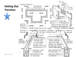
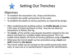
The document details the procedures and practices for site setting-out in civil engineering, including objectives, equipment needed, and the roles of involved parties. Key topics include establishing horizontal and vertical controls, marking building corners, and the use of modern surveying equipment. It emphasizes the importance of proper site preparation and coordination among engineers, surveyors, and contractors.


![Setting Out
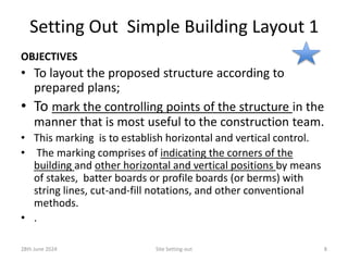
Definition [ISO]
• Setting out is
• the establishment of the marks and lines to
define the position
• and level of the elements for the construction
work
• so that works may proceed with reference to
them.
28th June 2024 Site Setting-out 7](https://image.slidesharecdn.com/cie321sitesettingout28thjune2024-240727175225-5fb5da4b/85/Site-Setting-Out-presentation-slide-PPTX-7-320.jpg)
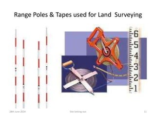
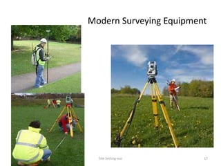
![Equipment for Setting-out Operation
For construction Setting-out works the following equipment are likely
to be used:
• Tapes [Class I or Class II]
• Compass
• Pegs
• String lines
• Line marking equipment
• Lump or marsh hammer
• Ranging poles or ranging
rods
• Plumb bobs
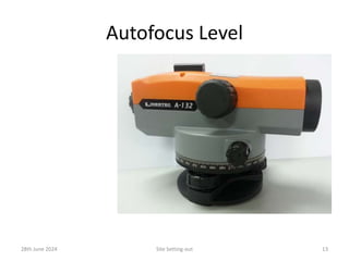
• Leveling equipment
• Dumpy levels, staves and tri-
pods
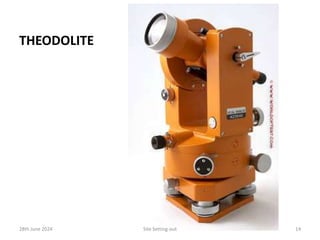
• Theodolite
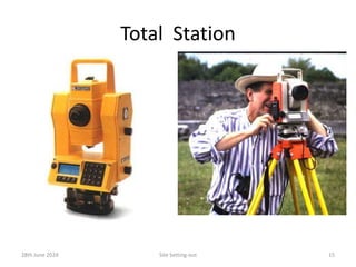
• Total Station [Electronic
Distance Measurement (EDM)]
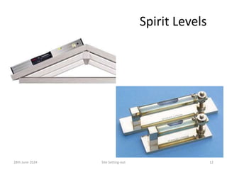
• Spirit levels,
• Water levels,
• PPE –Personal Protective
Equipment (e.g. Coloured vest,
safety boots, sun hat, sun
screen lotion etc.)
28th June 2024 Site Setting-out 10](https://image.slidesharecdn.com/cie321sitesettingout28thjune2024-240727175225-5fb5da4b/85/Site-Setting-Out-presentation-slide-PPTX-10-320.jpg)
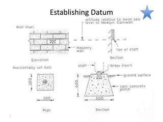

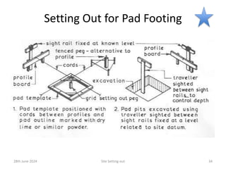
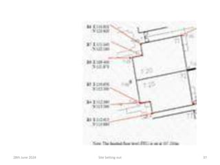
![Setting Out for
Reduced Level
Excavations
.
The overall outline
of the reduced level
area can be set out
using a theodolite ,
ranging rods, rope
and pegs, with
reference to a
baseline.
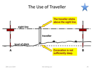
To control the depth
of excavation, sight
rails are set up at a
convenient height
and at positions [5m
x 5m grid] which will
enable a traveller to
be used.
28th June 2024 Site Setting-out 41
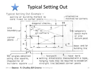
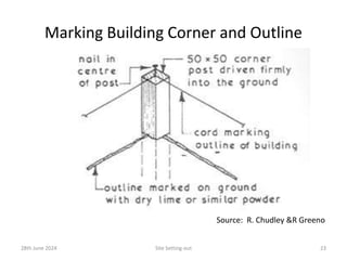
Source: R. Chudley an d R. Greeno, Building Construction Handbook](https://image.slidesharecdn.com/cie321sitesettingout28thjune2024-240727175225-5fb5da4b/85/Site-Setting-Out-presentation-slide-PPTX-41-320.jpg)
![Responsibility
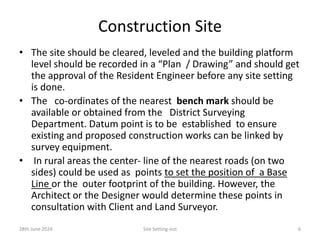
• The Contractor is fully responsible for the true and proper setting-
out of the works as per Drawings supplied to the Contractor.
• The Resident Engineer usually checks the setting-out. If errors are
found contractor shall rectify the errors.
• Read: General Conditions of Contract for Civil Engineering Works,
Clause 19, 1999 Edition [The Government of the Hong Kong Special
Administrative Region]. Available in the Internet
• http://www.devb.gov.hk/filemanager/en/content_188/gf548.pdf
• .
28th June 2024 Site Setting-out 47](https://image.slidesharecdn.com/cie321sitesettingout28thjune2024-240727175225-5fb5da4b/85/Site-Setting-Out-presentation-slide-PPTX-47-320.jpg)
![References
1. Roy Chudley & Roger Greeno, Building Construction Handbook, Routledge, ,
NY, 2014.
2. Module 8 –Surveying and Setting-Out :
http://www.ilo.org/public/english/employment/recon/eiip/download/surve
y_setout.pdf [This is for Road Survey & Construction]
3. RTF3217A , Set-out site for construction works, Industry Skills Councils, May
2012. Department of Education, Employment and Workplace Relations,
Australia. Release 1.
4. ISO 7078: 1985 (2012 Review), Building Construction – procedures for
setting out, measurement and surveying –Vocabulary and Guidance Notes.
5. Jack Stroud Foster & Raymond Harington; Structure and Fabric Part 2, 5th
edition, Longman, 1996 Reprint.
6. M.J. Tomlinson, Foundation Design & Construction, 6th ed., Longman 1995.
7. The Institution of Civil Engineers,, UK :ICE Design Practice Guidelines: The
Management of Setting Out IN Construction, Thgomas Telford Publication,
1997
Site Setting-out 52
28th June 2024](https://image.slidesharecdn.com/cie321sitesettingout28thjune2024-240727175225-5fb5da4b/85/Site-Setting-Out-presentation-slide-PPTX-52-320.jpg)


![PCC [Autosaved].pptx](https://cdn.slidesharecdn.com/ss_thumbnails/pccautosaved-231006060337-22bcfbd0-thumbnail.jpg?width=640&height=640&fit=bounds)


