Download to read offline
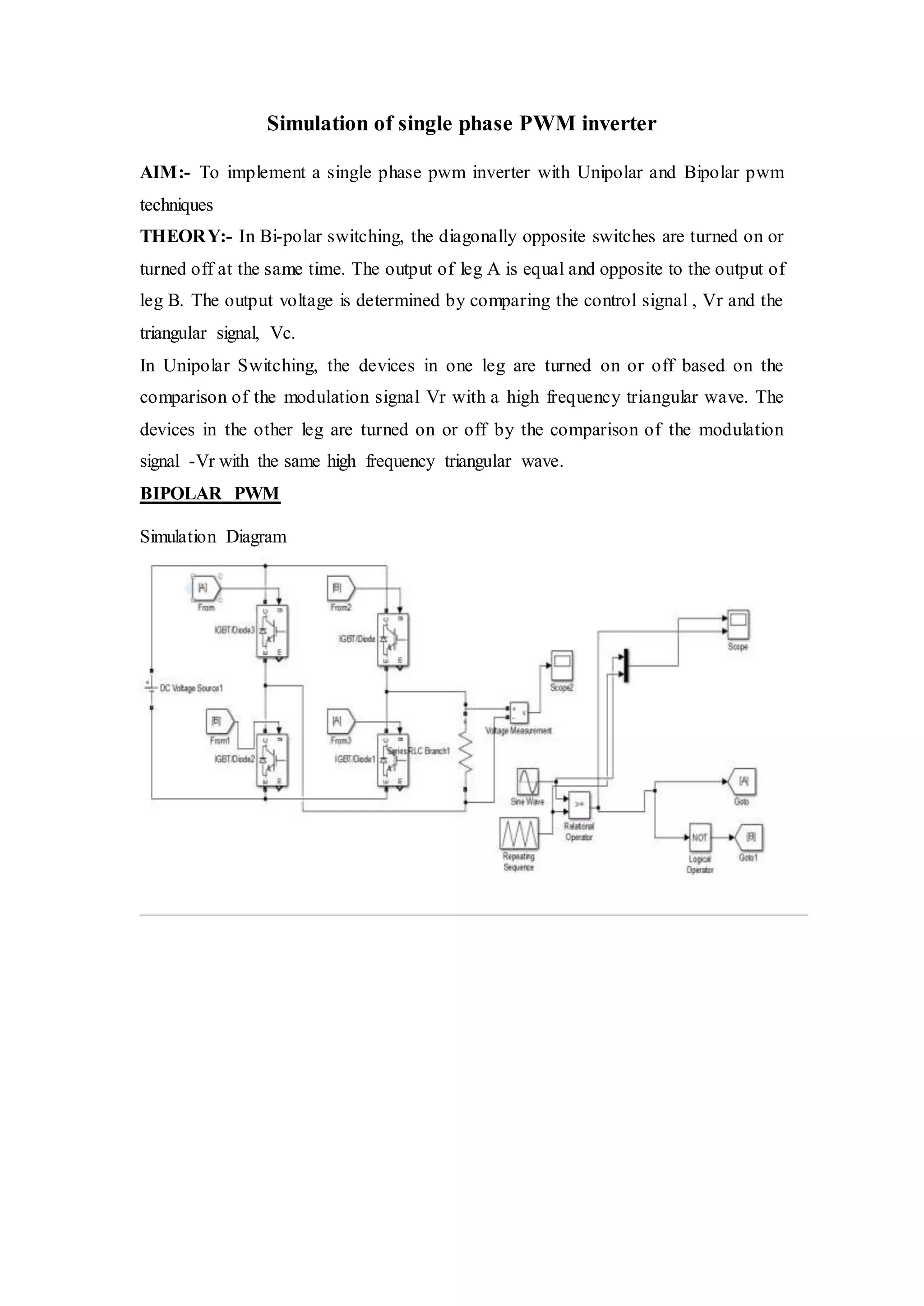
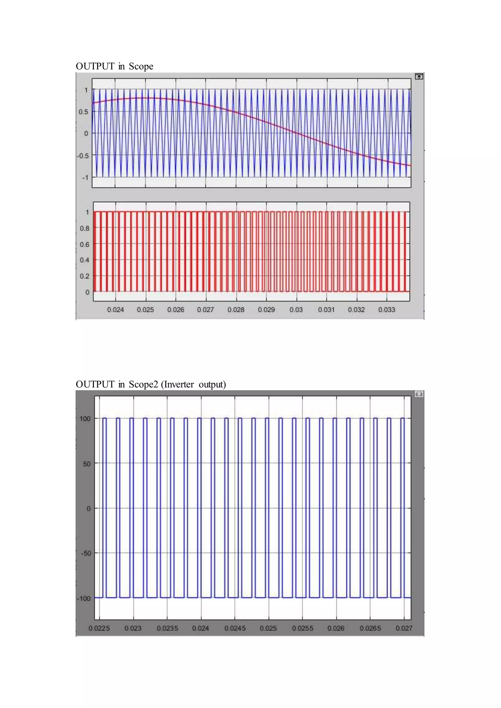

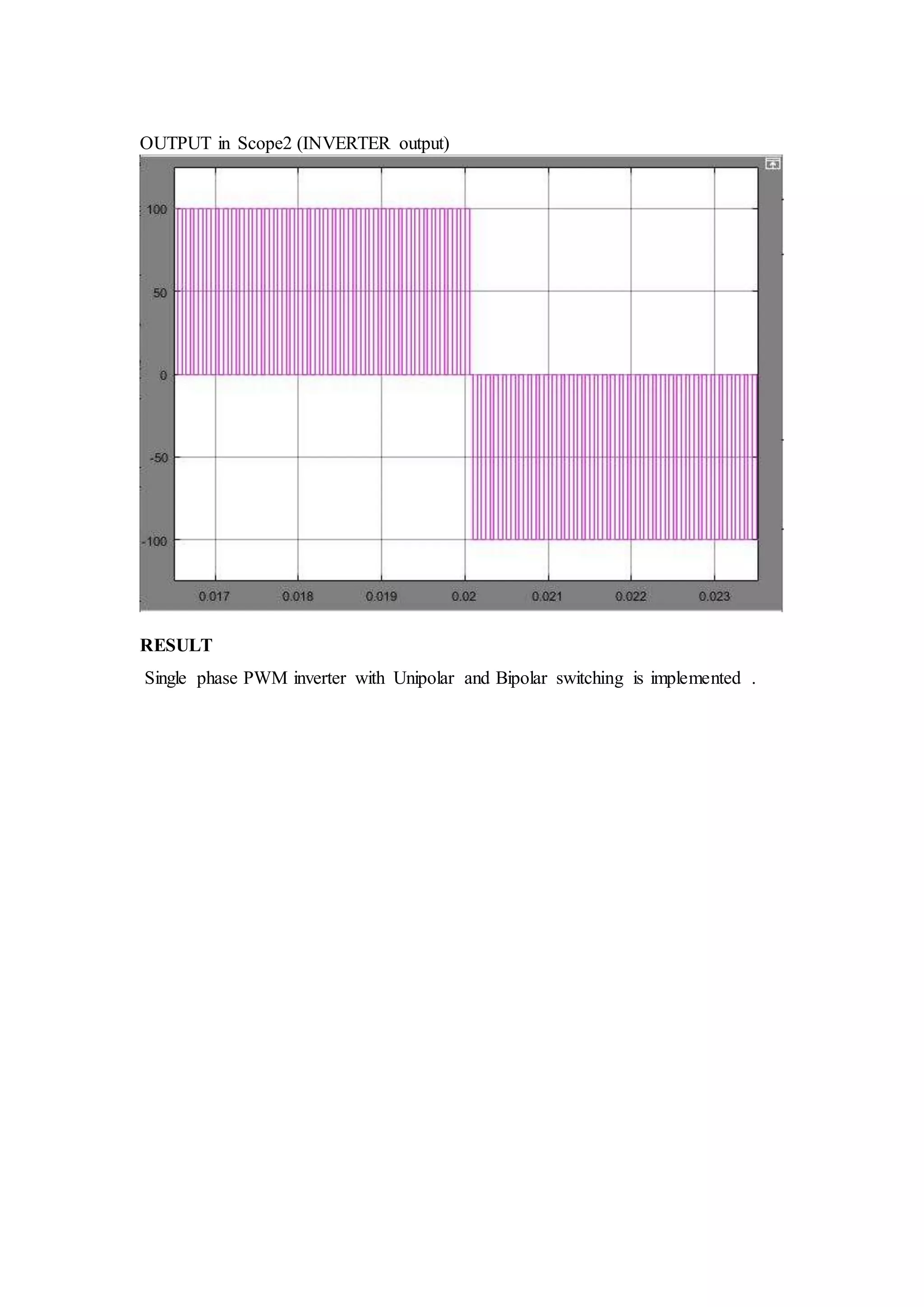
This document discusses simulating a single phase PWM inverter using unipolar and bipolar PWM techniques. It explains that bipolar switching turns on opposite switches simultaneously, resulting in an output voltage determined by comparing a control signal to a triangular carrier wave. Unipolar switching instead compares the control signal and its inverse separately to the carrier wave to determine switching of each leg. The document includes simulation diagrams and scope outputs comparing the unipolar and bipolar PWM inverter outputs.


