Downloaded 53 times

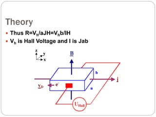
![Hall effect - principles
Consider a block of conducting medium through
which a current of electrons is flowing caused by
an external field
A magnetic filed B is established across the
conductor, perpendicular to the current (.
The electrons flow at a velocity v
A force perpendicular to both the current and
field is established.
F= qvBsinvb [N]](https://image.slidesharecdn.com/currentandpowerusinghallsensors-150509072009-lva1-app6891/85/Current-and-power-using-hall-sensors-3-320.jpg)
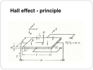
![Hall effect - principles
The electrons are pulled towards the front
side surface of the conductor (holes in
semiconductors move towards the back)
A voltage develops between the back
(positive) and front (negative) surface. This
voltage is the Hall voltage and is given by:
Vout = IB
qnd
V
d is the thickness of the hall plate,
n is the carrier density [charges/m3] and
q is the charge of the electron [C]](https://image.slidesharecdn.com/currentandpowerusinghallsensors-150509072009-lva1-app6891/85/Current-and-power-using-hall-sensors-6-320.jpg)
![ If the current changes direction or the magnetic
field changes direction, the polarity of the Hall
voltage flips.
The Hall effect sensor is polarity dependent,
may be used to measure direction of a field
or direction of motion if the sensor is properly set up.
The term 1/qn [m3/C] is material dependent
and is called the Hall coefficient KH.](https://image.slidesharecdn.com/currentandpowerusinghallsensors-150509072009-lva1-app6891/85/Current-and-power-using-hall-sensors-7-320.jpg)
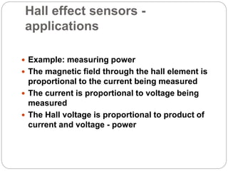
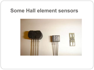
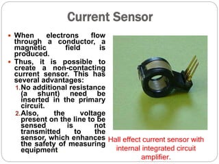


This document discusses Hall effect sensors and their applications. Hall effect sensors use the Hall effect principle to sense magnetic fields or electric current. They have simple and inexpensive designs, producing an output voltage proportional to the magnetic field. Common applications include sensing motor speed and position, measuring current, and detecting changes in magnetic fields. Hall effect sensors are widely used due to their low cost, ease of integration, and ability to provide non-contact sensing of magnetic fields and current.