This document summarizes key concepts about fatigue failure from variable loading from Shigley's Mechanical Engineering Design textbook. It discusses that fluctuating stresses over long periods of time can cause failure at stress levels lower than ultimate strength. Fatigue failure occurs in three stages: microcrack development, crack growth, and sudden fracture. Fatigue cracks initiate at locations of stress concentrations like holes or notches. The document presents three methods for predicting fatigue life: the stress-life method, strain-life method, and fracture mechanics method. It also discusses modifying factors for determining endurance limits and fatigue strength values accounting for effects of surface finish, size, temperature, reliability, and stress concentrations.
This presentation is by Flt Lt Dinesh Gupta, Associate Professor (Mechanical Engineering) NIET, Alwar (Rajasthan). It covers topic on Fluctuating Stresses related to Machine Design subject.
Rolling contact bearings and design procedureJashavant singh
this slide will give you idea about the rolling contact bearing , its types application areas and also you will learn how to design rolling contact bearing ,
comparison between the rolling contact and sliding contact bearing , advantage and disadvantages.
Every material has certain strength, expressed in terms of stress or strain, beyond which it
fractures or fails to carry the load. Failure Criterion: A criterion used to hypothesize the failure.
Failure Theory: A Theory behind a failure criterion.
Need of Failure Theories:
(a) To design structural components and calculate margin of safety.
(b) To guide in materials development.
(c) To determine weak and strong directions.
Frame is a ladder shaped structure with two longitudinal rails/beams (Frame side members) and properly located many integrating and reinforcing cross members, which form the ladder structure that is used as the interface/platform between the power package and the body package in Automobiles.
Degradation of an object occurs as a result of the interaction between the environment or with the materials that form the object however, in the case of ceramics, environmental factors are the major cause. There are several ways in which ceramics break down physically and chemically.
IAS Interview: What UPSC is looking for?Jts Institute
JTS Institute is forefront runner in IAS Coaching institutes. At JTS Institute our aim is to make true your dream and fulfill the ambition to become an IAS Officer.
Bacterial genetics /certified fixed orthodontic courses by Indian dental acad...Indian dental academy
The Indian Dental Academy is the Leader in continuing dental education , training dentists in all aspects of dentistry and offering a wide range of dental certified courses in different formats.
Indian dental academy provides dental crown & Bridge,rotary endodontics,fixed orthodontics,
Dental implants courses.for details pls visit www.indiandentalacademy.com ,or call
0091-9248678078
In this presentation, we list down 10 things that students need to follow to crack IIT JEE. Besides IIT JEE, these points should also help students in cracking other exams.
genetics is a study of heredity, by studying microbial genetics, which is the most basic, one can extrapolate it to complex genetic studies of complex biological systems. effect of mutagens on genes is eye opening
International Journal of Computational Engineering Research (IJCER) is dedicated to protecting personal information and will make every reasonable effort to handle collected information appropriately. All information collected, as well as related requests, will be handled as carefully and efficiently as possible in accordance with IJCER standards for integrity and objectivity.
Structural Integrity Analysis: Chapter 3 Mechanical Properties of MaterialsIgor Kokcharov
Structural Integrity Analysis features a collection of selected topics on structural design, safety, reliability, redundancy, strength, material science, mechanical properties of materials, composite materials, welds, finite element analysis, stress concentration, failure mechanisms and criteria. The engineering approaches focus on understanding and concept visualization rather than theoretical reasoning. The structural engineering profession plays a key role in the assurance of safety of technical systems such as metallic structures, buildings, machines, and transport. The third chapter explains the engineering tests and fundamentals of mechanical properties of materials.
Tensile, Impact and Hardness Testing of Mild SteelGulfam Hussain
The main purpose of this report is to study the mechanical properties and
failure mode of mild steel. Three types of standard tests i.e. tensile test, impact
test, and hardness test were conducted on the standard specimens of mild steel.
From the tests, results were obtained; Tensile strength, Impact strength, and
hardness were calculated. It was observed that Tensile Strength, Impact Strength
and Hardness of MS specimen were 1450.833 N/mm², 29.5 J & 59.25 HRB.
Event Management System Vb Net Project Report.pdfKamal Acharya
In present era, the scopes of information technology growing with a very fast .We do not see any are untouched from this industry. The scope of information technology has become wider includes: Business and industry. Household Business, Communication, Education, Entertainment, Science, Medicine, Engineering, Distance Learning, Weather Forecasting. Carrier Searching and so on.
My project named “Event Management System” is software that store and maintained all events coordinated in college. It also helpful to print related reports. My project will help to record the events coordinated by faculties with their Name, Event subject, date & details in an efficient & effective ways.
In my system we have to make a system by which a user can record all events coordinated by a particular faculty. In our proposed system some more featured are added which differs it from the existing system such as security.
Welcome to WIPAC Monthly the magazine brought to you by the LinkedIn Group Water Industry Process Automation & Control.
In this month's edition, along with this month's industry news to celebrate the 13 years since the group was created we have articles including
A case study of the used of Advanced Process Control at the Wastewater Treatment works at Lleida in Spain
A look back on an article on smart wastewater networks in order to see how the industry has measured up in the interim around the adoption of Digital Transformation in the Water Industry.
NO1 Uk best vashikaran specialist in delhi vashikaran baba near me online vas...Amil Baba Dawood bangali
Contact with Dawood Bhai Just call on +92322-6382012 and we'll help you. We'll solve all your problems within 12 to 24 hours and with 101% guarantee and with astrology systematic. If you want to take any personal or professional advice then also you can call us on +92322-6382012 , ONLINE LOVE PROBLEM & Other all types of Daily Life Problem's.Then CALL or WHATSAPP us on +92322-6382012 and Get all these problems solutions here by Amil Baba DAWOOD BANGALI
#vashikaranspecialist #astrologer #palmistry #amliyaat #taweez #manpasandshadi #horoscope #spiritual #lovelife #lovespell #marriagespell#aamilbabainpakistan #amilbabainkarachi #powerfullblackmagicspell #kalajadumantarspecialist #realamilbaba #AmilbabainPakistan #astrologerincanada #astrologerindubai #lovespellsmaster #kalajaduspecialist #lovespellsthatwork #aamilbabainlahore#blackmagicformarriage #aamilbaba #kalajadu #kalailam #taweez #wazifaexpert #jadumantar #vashikaranspecialist #astrologer #palmistry #amliyaat #taweez #manpasandshadi #horoscope #spiritual #lovelife #lovespell #marriagespell#aamilbabainpakistan #amilbabainkarachi #powerfullblackmagicspell #kalajadumantarspecialist #realamilbaba #AmilbabainPakistan #astrologerincanada #astrologerindubai #lovespellsmaster #kalajaduspecialist #lovespellsthatwork #aamilbabainlahore #blackmagicforlove #blackmagicformarriage #aamilbaba #kalajadu #kalailam #taweez #wazifaexpert #jadumantar #vashikaranspecialist #astrologer #palmistry #amliyaat #taweez #manpasandshadi #horoscope #spiritual #lovelife #lovespell #marriagespell#aamilbabainpakistan #amilbabainkarachi #powerfullblackmagicspell #kalajadumantarspecialist #realamilbaba #AmilbabainPakistan #astrologerincanada #astrologerindubai #lovespellsmaster #kalajaduspecialist #lovespellsthatwork #aamilbabainlahore #Amilbabainuk #amilbabainspain #amilbabaindubai #Amilbabainnorway #amilbabainkrachi #amilbabainlahore #amilbabaingujranwalan #amilbabainislamabad
Forklift Classes Overview by Intella PartsIntella Parts
Discover the different forklift classes and their specific applications. Learn how to choose the right forklift for your needs to ensure safety, efficiency, and compliance in your operations.
For more technical information, visit our website https://intellaparts.com
Automobile Management System Project Report.pdfKamal Acharya
The proposed project is developed to manage the automobile in the automobile dealer company. The main module in this project is login, automobile management, customer management, sales, complaints and reports. The first module is the login. The automobile showroom owner should login to the project for usage. The username and password are verified and if it is correct, next form opens. If the username and password are not correct, it shows the error message.
When a customer search for a automobile, if the automobile is available, they will be taken to a page that shows the details of the automobile including automobile name, automobile ID, quantity, price etc. “Automobile Management System” is useful for maintaining automobiles, customers effectively and hence helps for establishing good relation between customer and automobile organization. It contains various customized modules for effectively maintaining automobiles and stock information accurately and safely.
When the automobile is sold to the customer, stock will be reduced automatically. When a new purchase is made, stock will be increased automatically. While selecting automobiles for sale, the proposed software will automatically check for total number of available stock of that particular item, if the total stock of that particular item is less than 5, software will notify the user to purchase the particular item.
Also when the user tries to sale items which are not in stock, the system will prompt the user that the stock is not enough. Customers of this system can search for a automobile; can purchase a automobile easily by selecting fast. On the other hand the stock of automobiles can be maintained perfectly by the automobile shop manager overcoming the drawbacks of existing system.
About
Indigenized remote control interface card suitable for MAFI system CCR equipment. Compatible for IDM8000 CCR. Backplane mounted serial and TCP/Ethernet communication module for CCR remote access. IDM 8000 CCR remote control on serial and TCP protocol.
• Remote control: Parallel or serial interface.
• Compatible with MAFI CCR system.
• Compatible with IDM8000 CCR.
• Compatible with Backplane mount serial communication.
• Compatible with commercial and Defence aviation CCR system.
• Remote control system for accessing CCR and allied system over serial or TCP.
• Indigenized local Support/presence in India.
• Easy in configuration using DIP switches.
Technical Specifications
Indigenized remote control interface card suitable for MAFI system CCR equipment. Compatible for IDM8000 CCR. Backplane mounted serial and TCP/Ethernet communication module for CCR remote access. IDM 8000 CCR remote control on serial and TCP protocol.
Key Features
Indigenized remote control interface card suitable for MAFI system CCR equipment. Compatible for IDM8000 CCR. Backplane mounted serial and TCP/Ethernet communication module for CCR remote access. IDM 8000 CCR remote control on serial and TCP protocol.
• Remote control: Parallel or serial interface
• Compatible with MAFI CCR system
• Copatiable with IDM8000 CCR
• Compatible with Backplane mount serial communication.
• Compatible with commercial and Defence aviation CCR system.
• Remote control system for accessing CCR and allied system over serial or TCP.
• Indigenized local Support/presence in India.
Application
• Remote control: Parallel or serial interface.
• Compatible with MAFI CCR system.
• Compatible with IDM8000 CCR.
• Compatible with Backplane mount serial communication.
• Compatible with commercial and Defence aviation CCR system.
• Remote control system for accessing CCR and allied system over serial or TCP.
• Indigenized local Support/presence in India.
• Easy in configuration using DIP switches.
Vaccine management system project report documentation..pdfKamal Acharya
The Division of Vaccine and Immunization is facing increasing difficulty monitoring vaccines and other commodities distribution once they have been distributed from the national stores. With the introduction of new vaccines, more challenges have been anticipated with this additions posing serious threat to the already over strained vaccine supply chain system in Kenya.
Courier management system project report.pdfKamal Acharya
It is now-a-days very important for the people to send or receive articles like imported furniture, electronic items, gifts, business goods and the like. People depend vastly on different transport systems which mostly use the manual way of receiving and delivering the articles. There is no way to track the articles till they are received and there is no way to let the customer know what happened in transit, once he booked some articles. In such a situation, we need a system which completely computerizes the cargo activities including time to time tracking of the articles sent. This need is fulfilled by Courier Management System software which is online software for the cargo management people that enables them to receive the goods from a source and send them to a required destination and track their status from time to time.
1. Shigley’s Mechanical Engineering Design, 9th
Ed. Class Notes by: Dr. Ala Hijazi
CH 6 Page 1 of 19
CH 6: Fatigue Failure Resulting from Variable Loading
Some machine elements are subjected to static loads and for such elements static
failure theories are used to predict failure (yielding or fracture). However, most
machine elements are subjected to varying or fluctuating stresses (due to the
movement) such as shafts, gears, bearings, cams & followers,etc.
Fluctuating stresses (repeated over long period of time) will cause a part to fail
(fracture) at a stress level much smaller than the ultimate strength (or even the yield
strength in some casses).
Unlike static loading where failure usualy can be detected before it happens (due to
the large deflections associated with plastic deformation), fatigue failures are usualy
sudden and therefore dangerous.
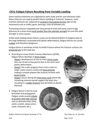
Fatigue failure is somehow similar to brittle fracture where the fracture surfaces are
prependicular to the load axis.
According to Linear-Elastic Fracture Mechanics (LEFM),
fatigue failure develops in three stages:
- Stage1: development of one or more micro cracks
(the size of two to five grains) due to the cyclic local
plastic deformation.
- Stage2: the cracks progress from micro cracks to
larger cracks (macro cracks) and keep growing
making a smooth plateau-like fracture surfaces with
beach marks.
- Stage3: occurs during the final stress cycle where the
remaining material cannot support the load, thus
resulting in a sudden fracture (can be brittle or ductile
fracture).
Fatigue failure is due to crack
formation and propagation.
Fatigue cracks usually initiate
at location with high stresses
such as discontinuities (hole,
notch, scratch, sharp corner,
crack, inclusions, etc.).
2. Shigley’s Mechanical Engineering Design, 9th
Ed. Class Notes by: Dr. Ala Hijazi
CH 6 Page 2 of 19
Fatigue cracks can also initiate at surfaces having rough surface finish or due to
the presence of tensile residual stresses. Thus all parts subjected to fatigue
loading are heat treated and polished in order to increase the fatigue life.
Fatigue Life Methods
Fatigue failure is a much more complicated phenomenon than static failure where
much complicating factors are involved. Also, testing materials for fatigue properties is
more complicated and much more time consuming than static testing.
Fatigue life methods are aimed to determine the life (number of loading cycles) of an
element until failure.
There are three major fatigue life methods where each is more accurate for some
types of loading or for some materials. The three methods are: the stress-life
method, the strain-life method, the linear-elastic fracture mechanics method.
The fatigue life is usually classified according to the number of loading cycles into:
Low cycle fatigue (1≤N≤1000) and for this low number of cycles, designers
sometimes ignore fatigue effects and just use static failure analysis.
High cycle fatigue (N>103
):
Finite life: from 103
→106
cycles
Infinite life: more than 106
cycles
The Strain-Life Method
This method relates the fatigue life to the amount of
plastic strain suffered by the part during the repeated
loading cycles.
When the stress in the material exceeds the yield
strength and the material is plastically deformed, the
material will be strain hardened and the yield strength
will increase if the part is reloaded again. However, if
the stress direction is reversed (from tension to
compression), the yield strength in the reversed
direction will be smaller than its initial value which
3. Shigley’s Mechanical Engineering Design, 9th
Ed. Class Notes by: Dr. Ala Hijazi
CH 6 Page 3 of 19
means that the material has been softened in the reverse loading direction. Each
time the stress is reversed, the yield strength in the other direction is decreased
and the material gets softer and undergoes more plastic deformation until fracture
occurs.
The strain-life method is applicable to Low-cycle fatigue.
The Linear Elastic Fracture Mechanics Method
This method assumes that a crack initiates in the material and it keeps growing until
failure occurs (the three stages described above).
The LEFM approach assumes that a small crack already exists in the material, and it
calculates the number of loading cycles required for the crack to grow to be large
enough to cause the remaining material to fracture completely.
This method is more applicable to High-cycle fatigue.
The Stress-Life Method
This method relates the fatigue life to the alternating stress level causing failure but it
does not give any explanation to why fatigue failure happens.
The stress-life relation is obtained experimentally using
Moore high-speed rotating beam test.
- The test is conducted by subjecting the rotating beam
to a pure bending moment (of a fixed known magnitude) until failure occurs.
(Due to rotation, the specimen is subjected to an alternating bending stress)
- The data obtained from the tests is used to generate the fatigue strength vs.
fatigue life diagram which is known as the S-N diagram.
- The first point is the ultimate strength which corresponds to failure in half a
cycle.
- The alternating stress amplitude is reduced below the ultimate strength and the
test is run until failure. The stress level and the number of cycles until failure
give a data point on the chart.
- The testing continues and each time the stress amplitude is reduced (such that
the specimen will live longer) and new point is obtained.
4. Shigley’s Mechanical Engineering Design, 9th
Ed. Class Notes by: Dr. Ala Hijazi
CH 6 Page 4 of 19
- For steel alloys the low-cycle
fatigue and the high-cycle
fatigue (finite and infinite)
can be recognized as having
different slopes. (they are
straight lines but keep in mind
it is a log-log curve)
- For steels if we keep reducing
the stress amplitude (for each
test) we will reach to a stress
level for which the specimen
will never fail, and this value
of stress is known as the Endurance Limit (Se).
- The number of stress cycles associated with the Endurance Limit defines the
boundary between Finite-life and Infinite-life, and it is usually between 106
to 107
cycles.
Steel and Titanium alloys have a clear endurance limit, but this is not true for all
materials.
For instance, Aluminum alloys does not have an endurance limit and for such
materials the fatigue strength is reported at 5(108
) cycles.
Also, most polymers do not have an endurance limit.
The Endurance Limit
The determination of the endurance limit is important for designing machine elements
that are subjected to High-cycle fatigue. The common practice when designing such
elements is to make sure that the fatigue stress level in the element is below the
endurance limit of the material being used.
Finding the Endurance Limit using the rotating beam experiment is time consuming
where it requires testing many samples and the time for each test is relatively long.
Therefore they try to relate the endurance limit to other mechanical properties
which are easier to find (such as the ultimate tensile strength).
5. Shigley’s Mechanical Engineering Design, 9th
Ed. Class Notes by: Dr. Ala Hijazi
CH 6 Page 5 of 19
The figure shows a plot of the
Endurance Limits versus Tensile
Strengths for a large number of
steel and iron specimens.
- The graph shows a correlation
between the ultimate strength
and endurance limit for
ultimate strengths up to 1400
then the endurance limit
seems to have a constant value.
- The relationship between the endurance limit and ultimate strength for steels is
given as:
The prime (‘) is used to denote that this is the endurance limit value
obtained for the test specimen (modifications are still needed).
Endurance Limit Modifications Factors
Endurance limit is obtained from the rotating beam test. The test is conducted under
closely controlled conditions (polished specimen of small size at a constant known
temperature, etc.). It is not realistic to expect a machine element to have the exact
same endurance limit value as that obtained from the rotating beam test because it
has different conditions (size, surface finish, manufacturing process, environment, etc.)
Thus some modifications factors are used to correlate the endurance limit for a
given mechanical element to the value obtained from tests:
Where,
Finish
Size
Reliability
Misc.Temp.
Load
6. Shigley’s Mechanical Engineering Design, 9th
Ed. Class Notes by: Dr. Ala Hijazi
CH 6 Page 6 of 19
: The endurance limit at the critical location of a machine element with the
geometry and conditions of use.
: The endurance limit obtained from the rotating beam test.
: Modification factors (obtained experimentally).
Surface Condition Factor ( )
The rotating-beam test specimens are highly polished. A rough surface finish will
reduce the endurance limit because there will be a higher potential for crack initiation.
The surface condition modification factor depends on the surface finish of the part
(ground, machined, as forged, etc.) and on the tensile strength of the material. It is
given as:
Constants & depend on surface condition and are given in Table 6-2.
Size Factor ( )
The rotating-beam specimens have a specific (small) diameter. Parts of larger size are
more likely to contain flaws and to have more non-homogeneities.
The size factor is given as:
where is the diameter, and
for axial loading
When a circular shaft is not rotating we use an effective diameter value instead
of the actual diameter, where:
For other cross-sections, is given in Table 6-3.
For bending
and torsion
7. Shigley’s Mechanical Engineering Design, 9th
Ed. Class Notes by: Dr. Ala Hijazi
CH 6 Page 7 of 19
Loading Factor ( )
The rotating-beam specimen is loaded in bending. Other types of loading will have a
different effect.
The load factor for the different types of loading is:
Temperature Factor ( )
When the operating temperature is below room temperature, the material becomes
more brittle. When the temperature is high the yield strength decreases and the
material becomes more ductile (and creep may occur).
For steels, the endurance limit slightly increases as temperature rises, then it starts
to drop. Thus, the temperature factor is given as:
For
The same values calculated by the equation are also presented in Table 6-4
where:
Reliability Factor ( )
The endurance limit obtained from testing is usually reported at mean value (it has a
normal distribution with ).
For other values of reliability, is found from Table 6-5.
Miscellaneous-Effects Factor ( )
It is used to account for the reduction of endurance limit due to all other effects (such
as Residual stress, corrosion, cyclic frequency, metal spraying, etc.).
However, those effects are not fully characterized and usually not accounted for. Thus
we use ( ).
8. Shigley’s Mechanical Engineering Design, 9th
Ed. Class Notes by: Dr. Ala Hijazi
CH 6 Page 8 of 19
Stress Concentration and Notch Sensitivity
Under fatigue loading conditions, crack initiation and growth usually starts in locations
having high stress concentrations (such as grooves, holes, etc.). The presence of stress
concentration reduces the fatigue life of an element (and the endurance limit) and it
must be considered in fatigue failure analysis.
However, due to the difference in ductility, the effect of stress concentration on
fatigue properties is not the same for different materials.
For materials under fatigue loading, the maximum stress near a notch (hole, fillet,
etc.) is:
or
Where,
: is the nominal stress
: is the fatigue stress concentration factor which is a reduced value of the
stress concentration factor ( ) because of the difference in material
sensitivity to the presence of notches.
and is defined as:
Notch sensitivity ( ) is defined as:
or
The value of ranges from 0 to 1
(material is not sensitive)
(material is fully sensitive)
Thus,
or
For Steels and Aluminum (2024) the notch sensitivity for Bending and Axial
loading can be found from Figure 6-20 and for Torsion is found from Figure 6-21.
9. Shigley’s Mechanical Engineering Design, 9th
Ed. Class Notes by: Dr. Ala Hijazi
CH 6 Page 9 of 19
For cast iron, the notch sensitivity is very low from 0 to 0.2, but to be
conservative it is recommended to use
Heywood distinguished between different types of notches (hole, shoulder,
groove) and according to him, is found as:
Where, : radius
: is a constant that depends on the type of the notch.
For steels, for different types of notches is given in Table 6-15.
For simple loading, can be multiplied by the stress value, or the endurance limit
can be reduced by dividing it by . However, for combined loading each type of
stress has to be multiplied by its corresponding value.
Fatigue Strength
In some design applications the number of load cycles the element is subjected to is
limited (less than 106
) and therefore there is no need to design for infinite life using the
endurance limit.
In such cases we need to find the Fatigue
Strength associated with the desired life.
For the High-cycle fatigue (103
→106
), the line
equation is where the constants “ ”
(y intercept) and “ ” (slope) are determined
from the end points and as:
The modified
Neuber equation
is the modified
Endurance Limit
10. Shigley’s Mechanical Engineering Design, 9th
Ed. Class Notes by: Dr. Ala Hijazi
CH 6 Page 10 of 19
Where is the True Stress at Fracture and for steels with HB ≤ 500, it is
approximated as:
- can be related to as:
where is found as:
Using the above equations, the value of is found as a function
of (using ) and it is presented in graphical form in
Figure 6-18.
- If the value of ( ) is known, the constant can be directly found as:
and can be rewritten as:
- Thus for 103
≤ ≤106
, the fatigue strength associated with a given life ( ) is:
and the fatigue life ( ) at a given fatigue stress ( ) is found as:
Studies show that for ductile materials, the Fatigue Stress Concentration Factor ( )
reduces for , however the conservative approach is to use as is.
Example: For a rotating-beam specimen made of 1050 CD steel, find:
fraction of
For values less than
490 MPa, use
to be conservative
11. Shigley’s Mechanical Engineering Design, 9th
Ed. Class Notes by: Dr. Ala Hijazi
CH 6 Page 11 of 19
a) The endurance limit (Ne=106
)
b) The fatigue strength corresponding to ( ) cycles to failure
c) The expected life under a completely reversed stress of
Solution:
From Table A-20
a)
b)
c)
Note that no modifications are needed
since it is a specimen:
OR, easier, from Figure 6-18:
Then,
MPa
12. Shigley’s Mechanical Engineering Design, 9th
Ed. Class Notes by: Dr. Ala Hijazi
CH 6 Page 12 of 19
Example: The two axially loaded bars shown are made
of 1050 HR steel and have machined surfaces. The two
bars are subjected to a completely reversed load .
a) Estimate the maximum value of the load for
each of the two bars such that they will have
infinite life (ignore buckling).
b) Find the static and fatigue factors of safety &
for bar (B) if it is to be subjected to a completely
reversed load of .
c) Estimate the fatigue life of bar (B) under reversed
load of (use )
Solution:
From Table A-20 &
a)
Modifying factors:
- Surface factor: , from Table 6-2: ,
- Size factor: since the loading is axial
- Loading factor: (for axial loading)
- Other factors:
Stress concentration (for bar B):
From Figure A-13-3 with &
Using the modified Neuber equation:
From Table 6-15 for a groove:
Thus the maximum stress for each is,
Bar (A):
Bar (B):
13. Shigley’s Mechanical Engineering Design, 9th
Ed. Class Notes by: Dr. Ala Hijazi
CH 6 Page 13 of 19
And the maximum load for each is,
Bar (A):
Bar (B):
Note that the maximum load for bar (B) is smaller than that of bar (A)
because of the notch.
b) Static factor of safety :
From Table A-20: Ductile material, thus stress concentration is
not applicable.
Fatigue factor of safety :
c) If we calculate the fatigue factor of safety with we will find it to be
less than one and thus the bar will not have infinite life.
This gives more conservative results than dividing ( ) by , and using
as is.
14. Shigley’s Mechanical Engineering Design, 9th
Ed. Class Notes by: Dr. Ala Hijazi
CH 6 Page 14 of 19
Characterizing Fluctuating Stress
In the rotating-beam test, the specimen is subjected to
completely reversed stress cycles ( )
In the case of the rotating shaft subjected to both radial and axial loads (such as with
helical gears) the fluctuating stress pattern will be different since there will be a
component of stress that is always present (due to the axial load).
The following stress components can be defined for distinguishing different states
of fluctuating stress:
: Mean or average stress,
: Stress range,
: Stress amplitude (half of the stress range),
For uniform periodic fluctuating stress, & are used to characterize the stress
pattern.
We also define:
Stress ratio:
Amplitude ratio:
Some common types of fluctuating stress:
Completely reversed stress:
Repeated stress:
Tension
Compression
15. Shigley’s Mechanical Engineering Design, 9th
Ed. Class Notes by: Dr. Ala Hijazi
CH 6 Page 15 of 19
Fatigue Failure Criteria for Fluctuating Stress
When a machine element is subjected to completely reversed stress (zero mean,
) the endurance limit is obtained from the rotating-beam test (after applying
the necessary modifying factors).
However, when the mean (or midrange) is non-zero the situation is different and a
fatigue failure criteria is needed.
If we plot the alternating stress component ( ) vs. the mean stress component
( ), this will help in distinguishing the different fluctuating stress scenarios.
When & , this will be a completely reversed fluctuating stress.
When & , this will be a static stress.
Any combination of & will fall between the two extremes (completely
reversed & static).
General fluctuating stress:
(non-zero mean)
16. Shigley’s Mechanical Engineering Design, 9th
Ed. Class Notes by: Dr. Ala Hijazi
CH 6 Page 16 of 19
Different theories are proposed to predict failure in such cases:
Yield (Langer) line: It connects on the axis with on axis. But it is not
realistic because is usually larger than .
Soderberg line: The most conservative, it connects on axis with on axis.
ASME-elliptic line: Same as Soderberg but it uses an ellipse instead of the straight
line.
Goodman line: It considers failure due to static loading to be at rather than ,
thus it connects on axis with on axis using a straight line.
Gerber line: Same as Goodman but it uses a parabola instead of the straight line.
It should be noted that is the modified endurance limit.
The fatigue stress concentration factor ( ) should be multiplied with both &
for conservative results.
The load line represents any combination of and , the intersection of the load
line with any of the failure lines gives the limiting values and according to the
line it intercepts.
Where ( ) is the design factor
It fits experimental data better (see fig 6-25)
17. Shigley’s Mechanical Engineering Design, 9th
Ed. Class Notes by: Dr. Ala Hijazi
CH 6 Page 17 of 19
Modified Goodman (Goodman and Langer)
It combines the Goodman and Langer lines.
The slope of the loading line passing through the
intersection point of the two lines is called the
critical slope and it is found as:
According to the slope of the load line ( ), it could intersect any of the
two lines:
Where case is considered to be a static yielding failure.
If we plot the Modified Goodman on stress ( ) vs. mean stress ( ) axes we obtain
the complete Modified Goodman diagram where it defines a failure envelope such
that any alternating stress that falls inside the diagram will not cause failure.
The Complete Modified
Goodman Diagram
18. Shigley’s Mechanical Engineering Design, 9th
Ed. Class Notes by: Dr. Ala Hijazi
CH 6 Page 18 of 19
Also, there are other modified criteria:
Gerber-Langer (see Table 6-7)
ASME-elliptic-Langer (see Table 6-8)
Example: A diameter bar has been machined from AISI-1045 CD bar. The bar
will be subjected to a fluctuating tensile load varying from to . Because of the
ends fillet radius, is to be used.
Find the critical mean and alternating stress values and the fatigue factor of
safety according to the Modified Goodman fatigue criterion.
Solution:
From Table A-20
Modifying factors:
- Surface factor: (Table 6-2)
- Size factor: since the loading is axial
- Loading factor: (for axial loading)
- Other factors:
Fluctuating stress: ,
Applying to both components:
19. Shigley’s Mechanical Engineering Design, 9th
Ed. Class Notes by: Dr. Ala Hijazi
CH 6 Page 19 of 19
The plot shows that the load line
intersects the Goodman line:
See Example 6-12 from text