Download as PDF, PPTX

![Rev PA1Rev PA1 2
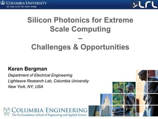
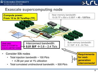
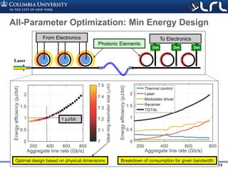
Trends in extreme HPC
• Evolution of the top10 in
the last six years:
– Average total compute power:
• 0.86 PFlops 21 PFlops
• ~24x increase
– Average nodal compute power:
• 31GFlops 600GFlops
• ~19x increase
– Average number of nodes
• 28k 35k
• ~1.3x increase
Node compute power main contributor to performance growth
2010 2011 2012 2013 2014 2015 2016
0.1
1
10
100
Node computer power (FLOPs)
Number of nodes
Total system compute power (FLOPs)
Average of top 10 sytems, relative to 2010
24x
19x
1.3x
[top500.org, S. Rumley, et al. Optical Interconnects for Extreme
Scale Computing Systems, Elsevier PARCO 64, 2017]](https://image.slidesharecdn.com/atpesc2017track-137-31930ambergman-siliconphotonics-171020143010/85/Silicon-Photonics-for-Extreme-Computing-Challenges-and-Opportunities-2-320.jpg)
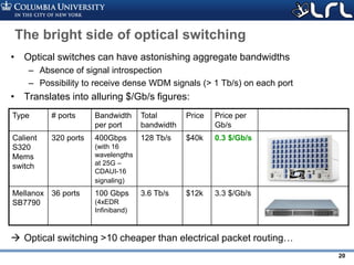
![Rev PA1Rev PA1 3
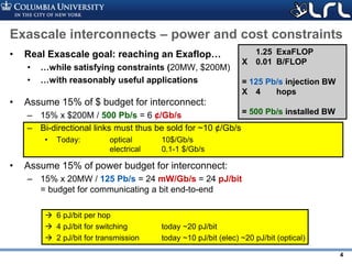
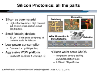
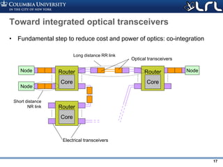
Interconnect trends
• Top 10 average node level
evolutions:
– Average node compute power:
• 31GFlops 600GFlops
• ~19x increase
– Average bandwidth available
per node
• 2.7GB/s 7.8GB/s
• ~3.2x increase
– Average byte-per-flop ratio
• 0.06 B/Flop 0.01 B/Flop
• ~6x decrease
• Sunway TaihuLight (#1) shows 0.004 B/Flop !!
Growing gap in interconnect bandwidth
2010 2011 2012 2013 2014 2015 2016
0.1
1
10
Node computer power (FLOPs)
Node bandwidth (bit/s)
Byte-per-flop ratio
Average of top 10 sytems, relative to 2010
19x
3.2x
0.17x
[top500.org, S. Rumley, et al. Optical Interconnects for Extreme
Scale Computing Systems, Elsevier PARCO 64, 2017]](https://image.slidesharecdn.com/atpesc2017track-137-31930ambergman-siliconphotonics-171020143010/85/Silicon-Photonics-for-Extreme-Computing-Challenges-and-Opportunities-3-320.jpg)
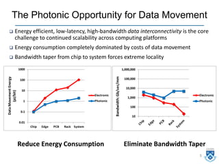

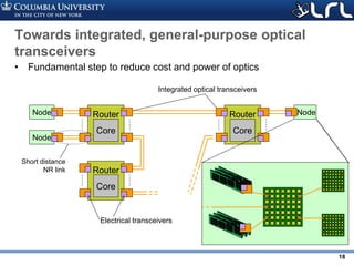
![Silicon Photonic Link Design
clk
dataTIA
clk
dataTIA
clk clk clk
data
R
C
clk
dataTIA
clk gen
Silicon waveguide Silicon waveguide
• Co-existence of Electronics and Photonics
• Energy-Bandwidth optimization
Clock Distribution
Serialization of Data
Driver
Comb Laser
Vertical Grating Coupler
Coupled Waveguides
OOK Modulation
Fiber
Thermal Tuning
Photodiode
“0”
“1”
λ
Deserialization
Demultiplexing Filter
Amplifier
[1] M. Bahadori et al. “Comprehensive Design Space Exploration of
Silicon Photonic Interconnects," IEEE JLT 34 (12), 2015.](https://image.slidesharecdn.com/atpesc2017track-137-31930ambergman-siliconphotonics-171020143010/85/Silicon-Photonics-for-Extreme-Computing-Challenges-and-Opportunities-11-320.jpg)
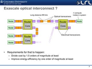
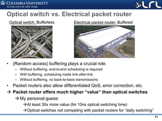
![Rev PA1Rev PA1 14
3 5 10 15 20 25
Optical channel ( ) linerate [Gb/s]
0
1
2
3
Linkenergyefficiency[pJ/bit] 10% Laser eff.
30% Laser eff.
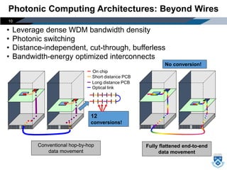
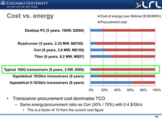
Highly parallel, “SERDES-less” links
• Investigate “many-channel” architectures with low bitrate wavelengths
– Leads to poor laser utilization
• Only possible with high laser efficiency
– But may allow drastic simplification of drivers and SERDES blocks
400G](https://image.slidesharecdn.com/atpesc2017track-137-31930ambergman-siliconphotonics-171020143010/85/Silicon-Photonics-for-Extreme-Computing-Challenges-and-Opportunities-14-320.jpg)
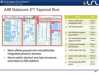
![Rev PA1Rev PA1 15
0 10 20 30
0
4
8
12
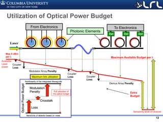
Cost per bandwidth – declining but slowly
• Today (2017):
– 100G (EDR) best
$/Gb/s figure
– Copper cable have
shorter reaches due to
higher bit-rate
– Optics: Not even ½
order of magnitude
price drop over 4
years
– But electrical-optical
gap is shrinking
[Besta et al. “Slim Fly: A Cost Effective
Low-Diameter Network Topology”,
SuperComputing 2014]
[may 2017]
Mellanox EDR
100 Gb/s
Length [m]
Cost[$/Gb/s]](https://image.slidesharecdn.com/atpesc2017track-137-31930ambergman-siliconphotonics-171020143010/85/Silicon-Photonics-for-Extreme-Computing-Challenges-and-Opportunities-15-320.jpg)
![Rev PA1Rev PA1 16
Packaging and connector drive costs
[Molex]
[Barwicz/IBM, OFC 2017]](https://image.slidesharecdn.com/atpesc2017track-137-31930ambergman-siliconphotonics-171020143010/85/Silicon-Photonics-for-Extreme-Computing-Challenges-and-Opportunities-16-320.jpg)
![Rev PA1Rev PA1 22
Our FPGA-Controlled Switch Test-Bed
• 16 high-speed DACs enable test
and control of integrated
photonic switch circuit
PIN shifter Thermal tuner
3dB coupler
Grating coupler array
FPGA with 16
high-speed
DACs/ADCs
On-chipLoss[dB]
1
2
3
4
5
Path category
B: Bar
C:cross
W: Waveguide
X: Crossing](https://image.slidesharecdn.com/atpesc2017track-137-31930ambergman-siliconphotonics-171020143010/85/Silicon-Photonics-for-Extreme-Computing-Challenges-and-Opportunities-22-320.jpg)
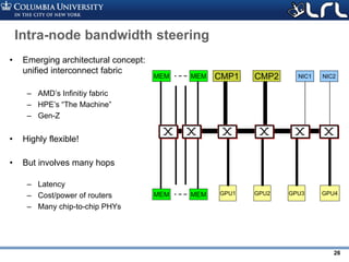
![Rev PA1Rev PA1 23
Transitioning to Novel Modular Architectures…
• Modular architecture and control
plane
• Avoids on chip crossings
• Fully non-blocking
• Path independent insertion loss
• Low crosstalk
[Dessislava Nikolova*, David M. Calhoun*, Yang Liu, Sébastien Rumley, Ari Novack, Tom Baehr-Jones, Michael Hochberg, Keren Bergman , Modular
architecture for fully non-blocking silicon photonic switch fabric , Nature Microsystems & Nanoengineering 3 (1607) (Jan 2017).]](https://image.slidesharecdn.com/atpesc2017track-137-31930ambergman-siliconphotonics-171020143010/85/Silicon-Photonics-for-Extreme-Computing-Challenges-and-Opportunities-23-320.jpg)
![Rev PA1Rev PA1 25
What optical networks are good at: bandwidth
steering
• Put your fibers where traffic is
• Example: 3D stencil traffic over Dragonfly
– 20 groups, 462 nodes per group, 24x24x16 stencil
• Per workload reconfiguration – avoids switching time overhead
• No need for ultra-large radixes – 8x8 is sufficient
[1] K. Wen, et al. “Flexfly: Enabling a Reconfigurable Dragonfly through Silicon Photonics”, SC 2016](https://image.slidesharecdn.com/atpesc2017track-137-31930ambergman-siliconphotonics-171020143010/85/Silicon-Photonics-for-Extreme-Computing-Challenges-and-Opportunities-25-320.jpg)

![Rev PA1Rev PA1 30
Conclusions
• Lack of bandwidth is threatening scalability
• For Exascale, need to work on (priority-sorted)
– Costs of the optical part
• Automated packaging and testing
• Increased integration
• Larger market
– Power of electrical part
• Packet routers
– Finely cost/performance-optimized
topologies [1]
• Taper optical bandwidth, but not too much
• Get as much as we can from optical cables
– Power of optical part
• Energy-wise optimized designs
• Improved laser efficiency (technology or “tricks”)
• Technological advances
– Costs of electrical part
[1] M.Y. Teh, et al. “Design space exploration of the Dragonfly topology”, Exacomm workshop (best paper), 2017](https://image.slidesharecdn.com/atpesc2017track-137-31930ambergman-siliconphotonics-171020143010/85/Silicon-Photonics-for-Extreme-Computing-Challenges-and-Opportunities-30-320.jpg)

The document discusses the role of silicon photonics in addressing challenges in extreme scale computing, emphasizing the need for energy-efficient, high-bandwidth interconnects. It highlights trends in high-performance computing, the evolving demands for bandwidth and energy efficiency, and the constraints of costs related to interconnect technologies. The potential of silicon photonics to significantly improve data movement in computing systems is explored, proposing advancements in optical switching and integration.


