Power Electronics
Dr. Imtiaz Hussain
Assistant Professor
email: imtiaz.hussain@faculty.muet.edu.pk
URL :http://imtiazhussainkalwar.weebly.com/
Lecture-5
Thyristors
1
• One of the most important type of power
semiconductor device.
• Compared to transistors, thyristors have lower on-
state conduction losses and higher power handling
capability.
• However, they have worse switching performances
than transistors.
• Name ‘thyristor’, is derived by a combination of the
capital letters from THYRatron and transISTOR.
Introduction
2
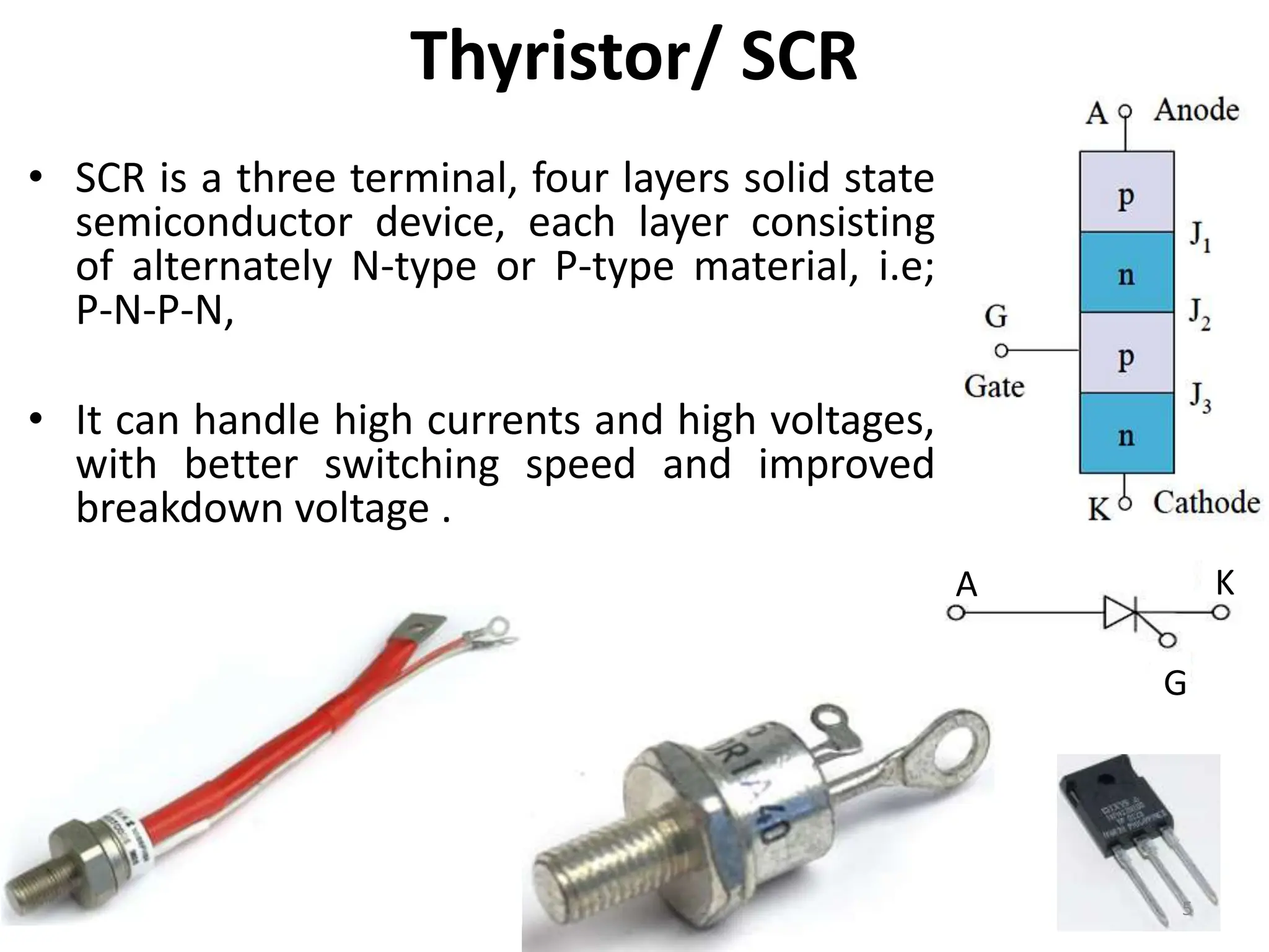
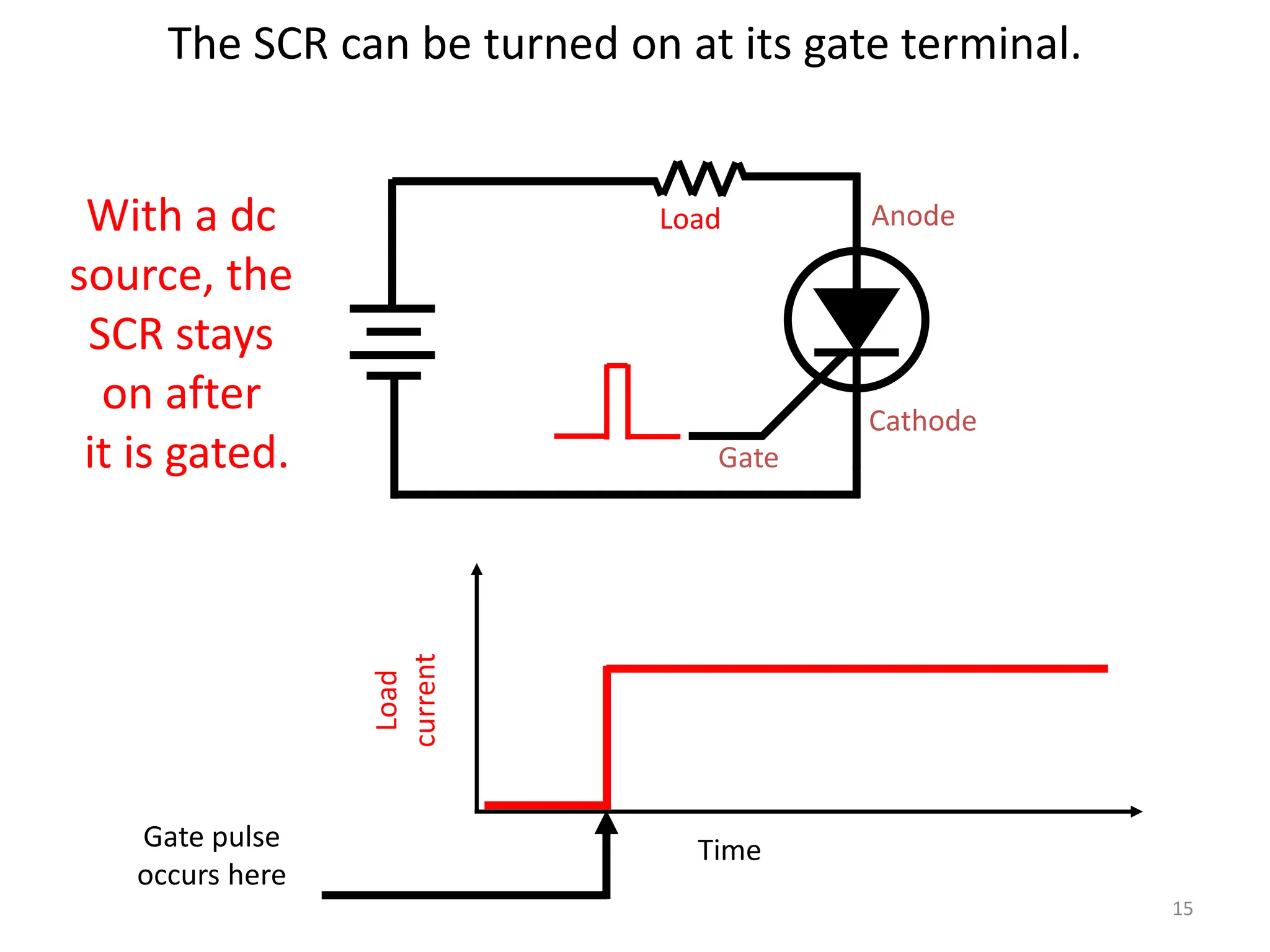
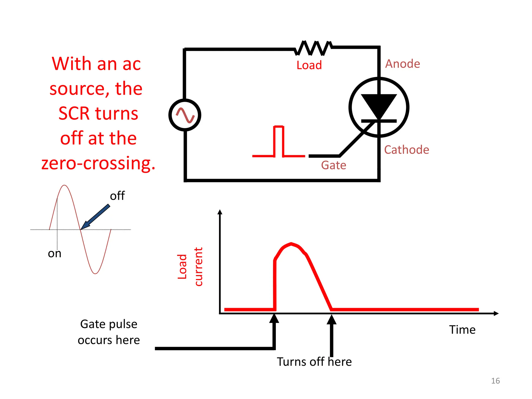
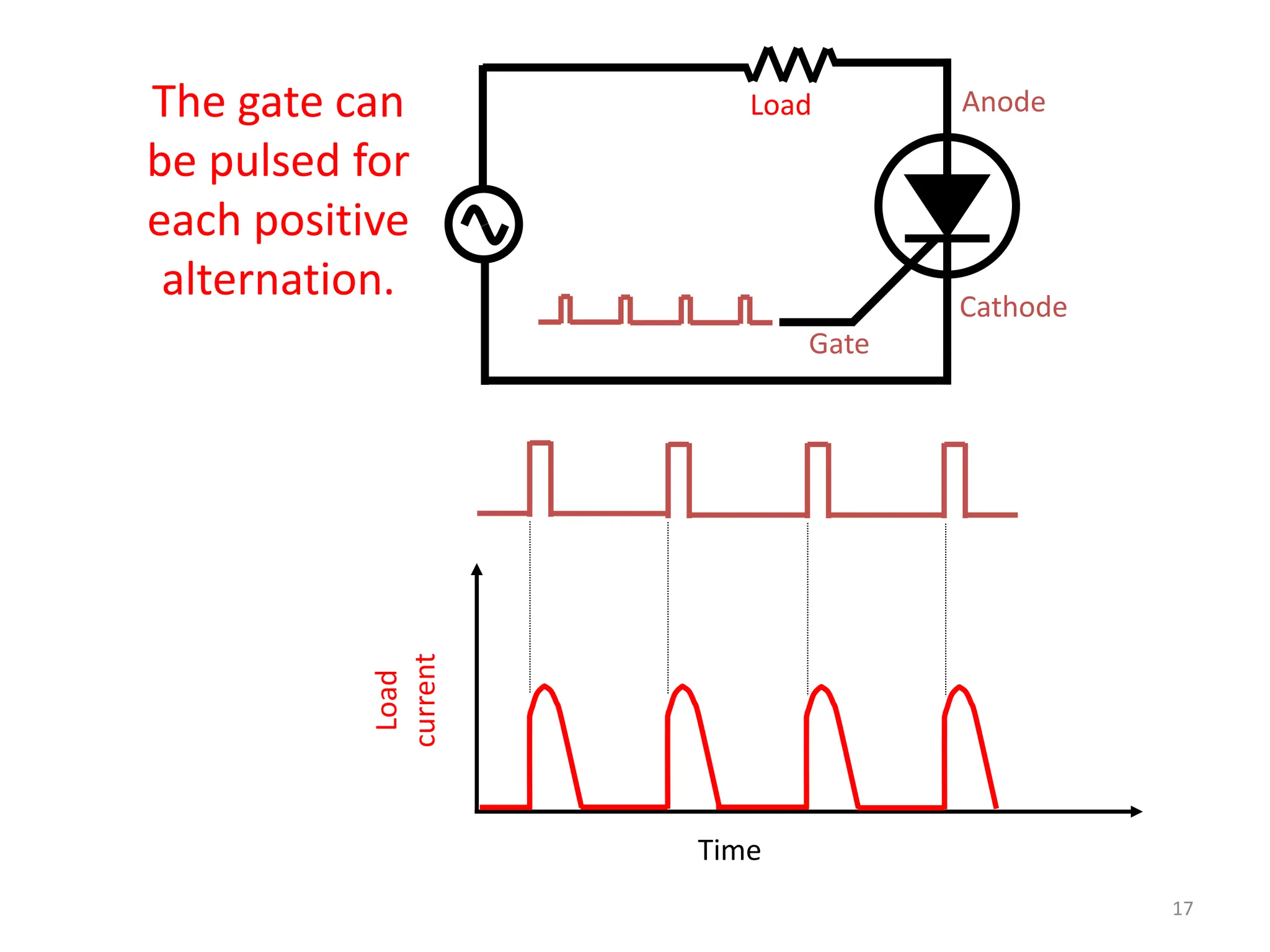
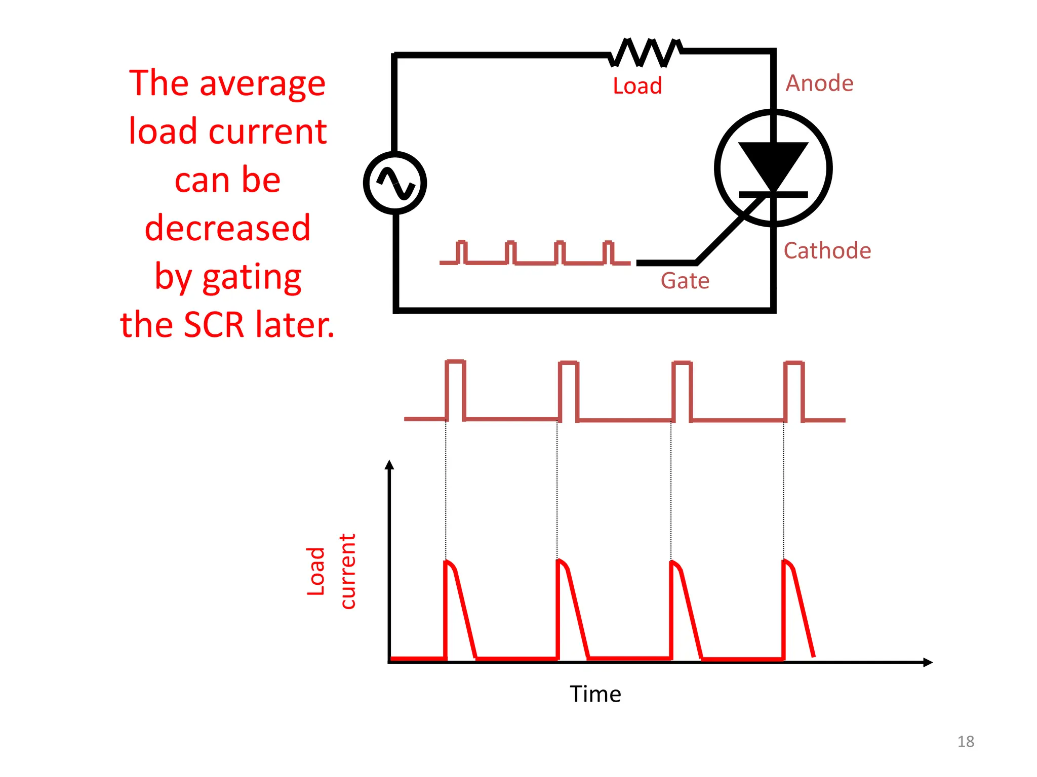
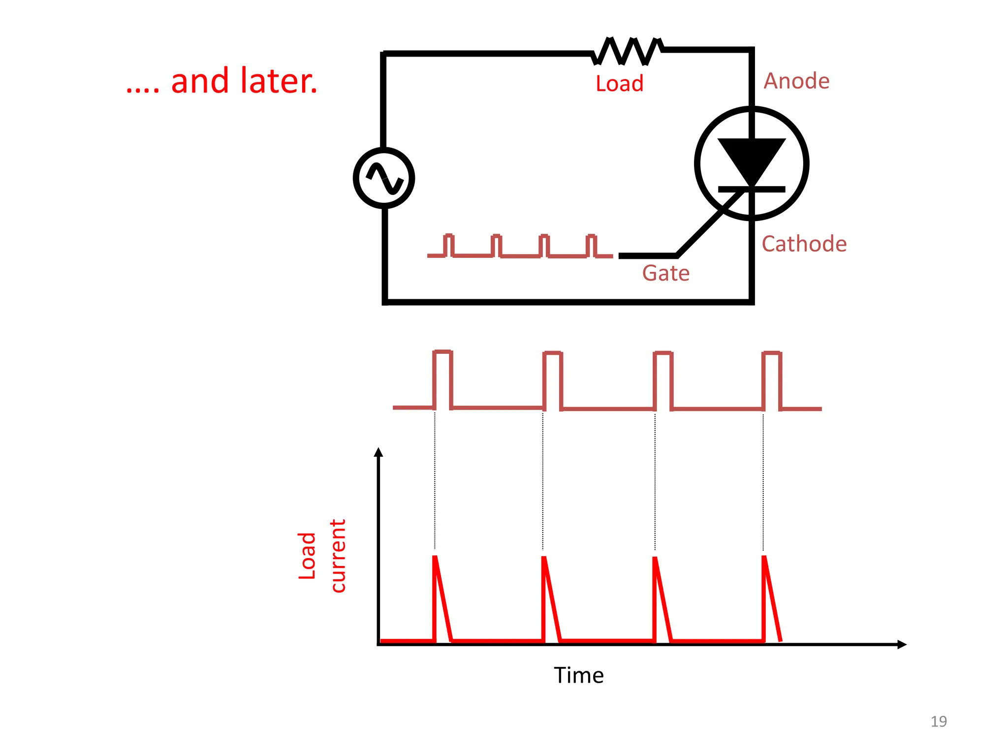
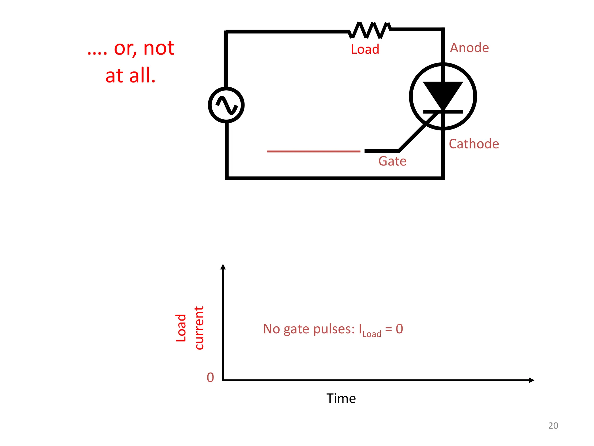
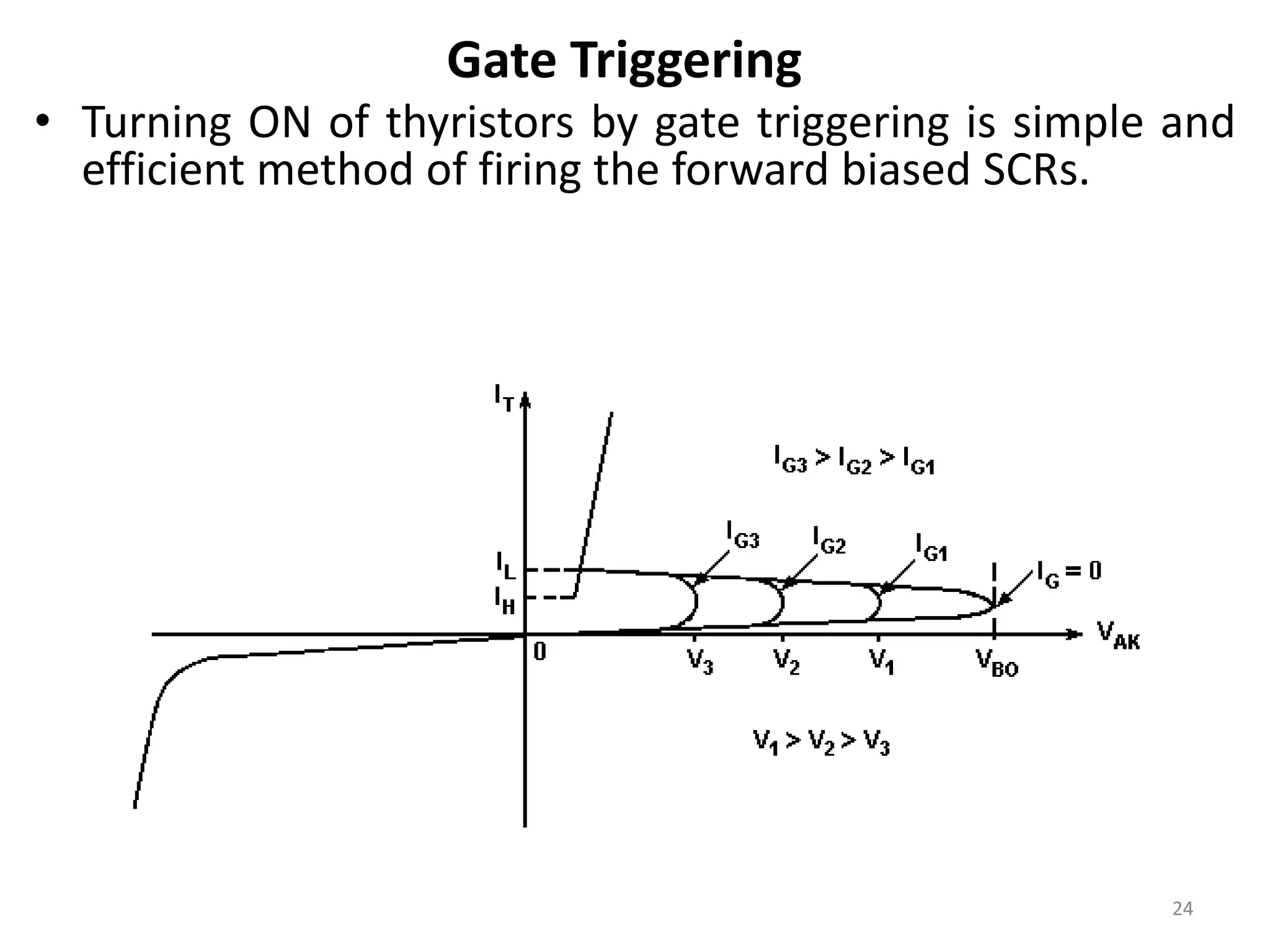
• Thyristors are four-layer pnpn power
semiconductor devices.
• These devices switch between conducting and
nonconducting states in response to a control
signal.
• Thyristors are used in timing circuits, AC motor
speed control and switching circuits.
Introduction
3
Thyristors
• Bell Laboratories were the first to fabricate a silicon-
based thyristor.
• Its first prototype was introduced by GE (USA) in 1957.
• Later on many other devices having characteristics
similar to of a thyristor were developed.
• These semiconductor devices are SCR, SCS, Triac, Diac,
PUT, GTO, e.t.c.
• This whole family of semiconductor devices is given
the name thyristors. 4
Thyristor/ SCR
• SCR is a three terminal, four layers solid state
semiconductor device, each layer consisting
of alternately N-type or P-type material, i.e;
P-N-P-N,
• It can handle high currents and high voltages,
with better switching speed and improved
breakdown voltage .
A K
G
5
Thyristor/ SCR
• Thyristor can handle high currents and high voltages.
• Typical rating are 1.5kA & 10kV which responds to 15MW
power handling capacity.
• This power can be controlled by a gate current of about 1A
only.
• Thyristor acts as a bistable switch.
– It conducts when gate receives a current pulse, and
continue to conduct as long as forward biased (till device
voltage is not reversed).
– They stay ON once they are triggered, and will go OFF only
if current is too low or when triggered off.
6
Thyristor/ SCR Operation
• When the anode voltage is made
positive with respect to the cathode,
junctions J1 and J3 are forward biased
and junction J2 is reverse biased.
• The thyristor is said to be in
the forward blocking or off-state
condition.
• A small leakage current flows from
anode to cathode and is called the off-
state current.
7
Thyristor/ SCR Operation
• If the anode voltage VAK is increased to a
sufficiently large value, the reverse biased
junction J2 would breakdown.
• This is known as avalanche breakdown and the
corresponding voltage is called the forward
breakdown voltage VBO.
• Since the other two junctions J1 and J3 are
already forward biased, there will be free
movement of carriers across all three junctions.
• This results in a large forward current and the
device is now said to be in a conducting or on-
state.
• The voltage drop across the device in the on-
state is due to the ohmic drop in the four layers
and is very small (in the region of 1 V).
8
Thyristor/ SCR
9
Thyristor Operating modes
Thyristors have three modes :
• Forward blocking mode:
Only leakage current flows,
so thyristor is not
conducting.
• Forward conducting mode:
large forward current flows
through the thyristor.
• Reverse blocking mode:
When cathode voltage is
increased to reverse
breakdown voltage ,
Avalanche breakdown
occurs and large current
flows.
10
Important characteristics
Latching Current IL
• This is the minimum anode current required to maintain
the thyristor in the on-state immediately after a thyristor
has been turned on and the gate signal has been removed.
• If a gate current greater than the threshold gate current is
applied until the anode current is greater than the latching
current IL then the thyristor will be turned on or triggered.
Holding Current IH
• This is the minimum anode current required to maintain
the thyristor in the on-state.
• To turn off a thyristor, the forward anode current must be
reduced below its holding current for a sufficient time for
mobile charge carriers to vacate the junction. 11
Important characteristics
Reverse Current IR
• When the cathode voltage is positive with respect to the
anode, the junction J2 is forward biased but
junctions J1 and J3 are reverse biased. The thyristor is said
to be in the reverse blocking state and a reverse leakage
current known as reverse current IR will flow through the
device.
Forward Breakover Voltage VBO
• If the forward voltage VAK is increased beyond VBO , the
thyristor can be turned on. But such a turn-on could be
destructive. In practice the forward voltage is maintained
below VBO and the thyristor is turned on by applying a
positive gate signal between gate and cathode.
12
13
Turn-on Characteristics
on d r
t t t
 
13
14
Turn-off Characteristics
Anode current
begins to
decrease
tC
tq
t
t
Commutation
di
dt
Recovery Recombination
t1 t2 t3 t4 t5
trr tgr
tq
tc
VAK
IA
tq=device off time
tc=circuit off time
14
Gate
Anode
Cathode
Load
current
Time
Gate pulse
occurs here
Load
With a dc
source, the
SCR stays
on after
it is gated.
The SCR can be turned on at its gate terminal.
15
Gate
Anode
Cathode
Load
current
Time
Gate pulse
occurs here
Load
With an ac
source, the
SCR turns
off at the
zero-crossing.
Turns off here
on
off
16
Gate
Anode
Cathode
Load
current
Time
Load
The gate can
be pulsed for
each positive
alternation.
17
Gate
Anode
Cathode
Load
current
Time
Load
The average
load current
can be
decreased
by gating
the SCR later.
18
Gate
Anode
Cathode
Load
current
Time
Load
…. and later.
19
Gate
Anode
Cathode
Load
current
Time
Load
…. or, not
at all.
No gate pulses: ILoad = 0
0
20
Thyristor turn-ON methods
• Thyristor turning ON is also known as Triggering.
• With anode is positive with respect to cathode, a thyristor
can be turned ON by any one of the following techniques :
– Forward voltage triggering
– Gate triggering
– dv/dt triggering
– Temperature triggering
– Light triggering
21
Forward Voltage Triggering
• When breakover voltage (VBO) across a thyristor is exceeded
than the rated maximum voltage of the device, thyristor
turns ON.
• At the breakover voltage the value of the thyristor anode
current is called the latching current (IL) .
• Breakover voltage triggering is not normally used as a
triggering method, and most circuit designs attempt to avoid
its occurrence.
• When a thyristor is triggered by exceeding VBO, the fall time
of the forward voltage is quite low (about 1/20th of the time
taken when the thyristor is gate-triggered).
22
Gate Triggering
• Turning ON of thyristors by gate triggering is simple and
efficient method of firing the forward biased SCRs.
• In Gate Triggering, thyristor with forward breakover
voltage (VBO), higher than the normal working voltage is
chosen.
• Whenever thyristor’s turn-ON is required, a positive gate
voltage b/w gate and cathode is applied.
• Forward voltage at which device switches to on-state
depends upon the magnitude of gate current.
– Higher the gate current, lower is the forward
breakover voltage .
23
Gate Triggering
• Turning ON of thyristors by gate triggering is simple and
efficient method of firing the forward biased SCRs.
24
dv/dt triggering
• With forward voltage across anode & cathode of a thyristor, two
outer junctions (A & C) are forward biased but the inner junction
(J2) is reverse biased.
• The reversed biased junction J2 behaves like a capacitor because of
the space-charge present there.
• As p-n junction has capacitance, so larger the junction area the
larger the capacitance.
• If a voltage ramp is applied across the anode-to-cathode, a current
will flow in the device to charge the device capacitance according
to the relation:
• If the charging current becomes large enough, density of moving
current carriers in the device induces switch-on.
• This method of triggering is not desirable because high charging
current (Ic) may damage the thyristor.
25
Temperature Triggering
• During forward blocking, most of the applied voltage
appears across reverse biased junction J2.
• This voltage across junction J2 associated with leakage
current may raise the temperature of this junction.
• With increase in temperature, leakage current through
junction J2 further increases.
• This cumulative process may turn on the SCR at some high
temperature.
• High temperature triggering may cause Thermal runaway
and is generally avoided.
26
Light Triggering
• In this method light particles (photons) are made to
strike the reverse biased junction, which causes an
increase in the number of electron hole pairs and
triggering of the thyristor.
• For light-triggered SCRs, a slot (niche) is made in the
inner p-layer.
• When it is irradiated, free charge carriers are
generated just like when gate signal is applied b/w
gate and cathode.
• Pulse light of appropriate wavelength is guided by
optical fibers for irradiation.
• If the intensity of this light thrown on the recess
exceeds a certain value, forward-biased SCR is turned
on. Such a thyristor is known as light-activated SCR
(LASCR).
• Light-triggered thyristors is mostly used in high-
voltage direct current (HVDC) transmission systems.
27
Thyristor Gate Control Methods
• An easy method to switch ON a SCR into conduction is to apply
a proper positive signal to the gate.
• This signal should be applied when the thyristor is forward
biased and should be removed after the device has been
switched ON.
• Thyristor turn ON time should be in range of 1-4 micro
seconds, while turn-OFF time must be between 8-50 micro
seconds.
• Thyristor gate signal can be of three varieties.
– D.C Gate signal
– A.C Gate Signal
– Pulse
28
Thyristor Gate Control Methods
D.C Gate signal: Application of a d.c gate signal causes the flow
of gate current which triggers the SCR.
– Disadvantage is that the gate signal has to be continuously
applied, resulting in power loss.
– Gate control circuit is also not isolated from the main
power circuit.
29
Thyristor Gate Control Methods
A.C Gate Signal: In this method a phase - shifted a.c voltage derived from
the mains supplies the gate signal.
– Instant of firing can be controlled by phase angle control of the gate
signal.
30
Thyristor Gate Control Methods
Pulse: Here the SCR is triggered by the application of a positive pulse of
correct magnitude.
– For Thyristors it is important to switched ON at proper instants in a
certain sequence.
– This can be done by train of the high frequency pulses at proper
instants through a logic circuit.
– A pulse transformer is used for circuit isolation.
31
Thyristor Commutation
• Commutation: Process of turning off a conducting thyristor
• SCR cannot be turned OFF via the gate terminal.
• It will turn-off only after the anode current is negated
either naturally or using forced commutation techniques.
• Therefore, commutation can be classified as
– Natural commutation
– Forced commutation
32
Line Commutation (Natural Commutation)
• Occurs only in AC circuits.
• Natural Commutation of thyristor takes place in
– AC Voltage Regulators
– Phase controlled rectifiers
– Cycloconverters
33
Thyristor Turn-Off: Line-Commutated Thyristor Circuit
34
Forced Commutation
• Applied to d.c circuits.
• If a thyristor is used in a DC circuit, when first turned on, it will stay
on until the current goes to zero. To turn off the thyristor it is
possible to use a Forced commutation circuit. The circuit creates a
reverse voltage over the thyristor (and a small reverse current) for
a short time, but long enough to turn off the thyristor.
35
END OF LECTURE-5
To download this lecture visit
http://imtiazhussainkalwar.weebly.com/
36

lecture_5_thyristorshjjjjjkjkkkmmmmmmmmmmm

  • 1.
    Power Electronics Dr. ImtiazHussain Assistant Professor email: imtiaz.hussain@faculty.muet.edu.pk URL :http://imtiazhussainkalwar.weebly.com/ Lecture-5 Thyristors 1
  • 2.
    • One ofthe most important type of power semiconductor device. • Compared to transistors, thyristors have lower on- state conduction losses and higher power handling capability. • However, they have worse switching performances than transistors. • Name ‘thyristor’, is derived by a combination of the capital letters from THYRatron and transISTOR. Introduction 2
  • 3.
    • Thyristors arefour-layer pnpn power semiconductor devices. • These devices switch between conducting and nonconducting states in response to a control signal. • Thyristors are used in timing circuits, AC motor speed control and switching circuits. Introduction 3
  • 4.
    Thyristors • Bell Laboratorieswere the first to fabricate a silicon- based thyristor. • Its first prototype was introduced by GE (USA) in 1957. • Later on many other devices having characteristics similar to of a thyristor were developed. • These semiconductor devices are SCR, SCS, Triac, Diac, PUT, GTO, e.t.c. • This whole family of semiconductor devices is given the name thyristors. 4
  • 5.
    Thyristor/ SCR • SCRis a three terminal, four layers solid state semiconductor device, each layer consisting of alternately N-type or P-type material, i.e; P-N-P-N, • It can handle high currents and high voltages, with better switching speed and improved breakdown voltage . A K G 5
  • 6.
    Thyristor/ SCR • Thyristorcan handle high currents and high voltages. • Typical rating are 1.5kA & 10kV which responds to 15MW power handling capacity. • This power can be controlled by a gate current of about 1A only. • Thyristor acts as a bistable switch. – It conducts when gate receives a current pulse, and continue to conduct as long as forward biased (till device voltage is not reversed). – They stay ON once they are triggered, and will go OFF only if current is too low or when triggered off. 6
  • 7.
    Thyristor/ SCR Operation •When the anode voltage is made positive with respect to the cathode, junctions J1 and J3 are forward biased and junction J2 is reverse biased. • The thyristor is said to be in the forward blocking or off-state condition. • A small leakage current flows from anode to cathode and is called the off- state current. 7
  • 8.
    Thyristor/ SCR Operation •If the anode voltage VAK is increased to a sufficiently large value, the reverse biased junction J2 would breakdown. • This is known as avalanche breakdown and the corresponding voltage is called the forward breakdown voltage VBO. • Since the other two junctions J1 and J3 are already forward biased, there will be free movement of carriers across all three junctions. • This results in a large forward current and the device is now said to be in a conducting or on- state. • The voltage drop across the device in the on- state is due to the ohmic drop in the four layers and is very small (in the region of 1 V). 8
  • 9.
  • 10.
    Thyristor Operating modes Thyristorshave three modes : • Forward blocking mode: Only leakage current flows, so thyristor is not conducting. • Forward conducting mode: large forward current flows through the thyristor. • Reverse blocking mode: When cathode voltage is increased to reverse breakdown voltage , Avalanche breakdown occurs and large current flows. 10
  • 11.
    Important characteristics Latching CurrentIL • This is the minimum anode current required to maintain the thyristor in the on-state immediately after a thyristor has been turned on and the gate signal has been removed. • If a gate current greater than the threshold gate current is applied until the anode current is greater than the latching current IL then the thyristor will be turned on or triggered. Holding Current IH • This is the minimum anode current required to maintain the thyristor in the on-state. • To turn off a thyristor, the forward anode current must be reduced below its holding current for a sufficient time for mobile charge carriers to vacate the junction. 11
  • 12.
    Important characteristics Reverse CurrentIR • When the cathode voltage is positive with respect to the anode, the junction J2 is forward biased but junctions J1 and J3 are reverse biased. The thyristor is said to be in the reverse blocking state and a reverse leakage current known as reverse current IR will flow through the device. Forward Breakover Voltage VBO • If the forward voltage VAK is increased beyond VBO , the thyristor can be turned on. But such a turn-on could be destructive. In practice the forward voltage is maintained below VBO and the thyristor is turned on by applying a positive gate signal between gate and cathode. 12
  • 13.
  • 14.
    14 Turn-off Characteristics Anode current beginsto decrease tC tq t t Commutation di dt Recovery Recombination t1 t2 t3 t4 t5 trr tgr tq tc VAK IA tq=device off time tc=circuit off time 14
  • 15.
    Gate Anode Cathode Load current Time Gate pulse occurs here Load Witha dc source, the SCR stays on after it is gated. The SCR can be turned on at its gate terminal. 15
  • 16.
    Gate Anode Cathode Load current Time Gate pulse occurs here Load Withan ac source, the SCR turns off at the zero-crossing. Turns off here on off 16
  • 17.
    Gate Anode Cathode Load current Time Load The gate can bepulsed for each positive alternation. 17
  • 18.
  • 19.
  • 20.
  • 21.
    Thyristor turn-ON methods •Thyristor turning ON is also known as Triggering. • With anode is positive with respect to cathode, a thyristor can be turned ON by any one of the following techniques : – Forward voltage triggering – Gate triggering – dv/dt triggering – Temperature triggering – Light triggering 21
  • 22.
    Forward Voltage Triggering •When breakover voltage (VBO) across a thyristor is exceeded than the rated maximum voltage of the device, thyristor turns ON. • At the breakover voltage the value of the thyristor anode current is called the latching current (IL) . • Breakover voltage triggering is not normally used as a triggering method, and most circuit designs attempt to avoid its occurrence. • When a thyristor is triggered by exceeding VBO, the fall time of the forward voltage is quite low (about 1/20th of the time taken when the thyristor is gate-triggered). 22
  • 23.
    Gate Triggering • TurningON of thyristors by gate triggering is simple and efficient method of firing the forward biased SCRs. • In Gate Triggering, thyristor with forward breakover voltage (VBO), higher than the normal working voltage is chosen. • Whenever thyristor’s turn-ON is required, a positive gate voltage b/w gate and cathode is applied. • Forward voltage at which device switches to on-state depends upon the magnitude of gate current. – Higher the gate current, lower is the forward breakover voltage . 23
  • 24.
    Gate Triggering • TurningON of thyristors by gate triggering is simple and efficient method of firing the forward biased SCRs. 24
  • 25.
    dv/dt triggering • Withforward voltage across anode & cathode of a thyristor, two outer junctions (A & C) are forward biased but the inner junction (J2) is reverse biased. • The reversed biased junction J2 behaves like a capacitor because of the space-charge present there. • As p-n junction has capacitance, so larger the junction area the larger the capacitance. • If a voltage ramp is applied across the anode-to-cathode, a current will flow in the device to charge the device capacitance according to the relation: • If the charging current becomes large enough, density of moving current carriers in the device induces switch-on. • This method of triggering is not desirable because high charging current (Ic) may damage the thyristor. 25
  • 26.
    Temperature Triggering • Duringforward blocking, most of the applied voltage appears across reverse biased junction J2. • This voltage across junction J2 associated with leakage current may raise the temperature of this junction. • With increase in temperature, leakage current through junction J2 further increases. • This cumulative process may turn on the SCR at some high temperature. • High temperature triggering may cause Thermal runaway and is generally avoided. 26
  • 27.
    Light Triggering • Inthis method light particles (photons) are made to strike the reverse biased junction, which causes an increase in the number of electron hole pairs and triggering of the thyristor. • For light-triggered SCRs, a slot (niche) is made in the inner p-layer. • When it is irradiated, free charge carriers are generated just like when gate signal is applied b/w gate and cathode. • Pulse light of appropriate wavelength is guided by optical fibers for irradiation. • If the intensity of this light thrown on the recess exceeds a certain value, forward-biased SCR is turned on. Such a thyristor is known as light-activated SCR (LASCR). • Light-triggered thyristors is mostly used in high- voltage direct current (HVDC) transmission systems. 27
  • 28.
    Thyristor Gate ControlMethods • An easy method to switch ON a SCR into conduction is to apply a proper positive signal to the gate. • This signal should be applied when the thyristor is forward biased and should be removed after the device has been switched ON. • Thyristor turn ON time should be in range of 1-4 micro seconds, while turn-OFF time must be between 8-50 micro seconds. • Thyristor gate signal can be of three varieties. – D.C Gate signal – A.C Gate Signal – Pulse 28
  • 29.
    Thyristor Gate ControlMethods D.C Gate signal: Application of a d.c gate signal causes the flow of gate current which triggers the SCR. – Disadvantage is that the gate signal has to be continuously applied, resulting in power loss. – Gate control circuit is also not isolated from the main power circuit. 29
  • 30.
    Thyristor Gate ControlMethods A.C Gate Signal: In this method a phase - shifted a.c voltage derived from the mains supplies the gate signal. – Instant of firing can be controlled by phase angle control of the gate signal. 30
  • 31.
    Thyristor Gate ControlMethods Pulse: Here the SCR is triggered by the application of a positive pulse of correct magnitude. – For Thyristors it is important to switched ON at proper instants in a certain sequence. – This can be done by train of the high frequency pulses at proper instants through a logic circuit. – A pulse transformer is used for circuit isolation. 31
  • 32.
    Thyristor Commutation • Commutation:Process of turning off a conducting thyristor • SCR cannot be turned OFF via the gate terminal. • It will turn-off only after the anode current is negated either naturally or using forced commutation techniques. • Therefore, commutation can be classified as – Natural commutation – Forced commutation 32
  • 33.
    Line Commutation (NaturalCommutation) • Occurs only in AC circuits. • Natural Commutation of thyristor takes place in – AC Voltage Regulators – Phase controlled rectifiers – Cycloconverters 33
  • 34.
  • 35.
    Forced Commutation • Appliedto d.c circuits. • If a thyristor is used in a DC circuit, when first turned on, it will stay on until the current goes to zero. To turn off the thyristor it is possible to use a Forced commutation circuit. The circuit creates a reverse voltage over the thyristor (and a small reverse current) for a short time, but long enough to turn off the thyristor. 35
  • 36.
    END OF LECTURE-5 Todownload this lecture visit http://imtiazhussainkalwar.weebly.com/ 36