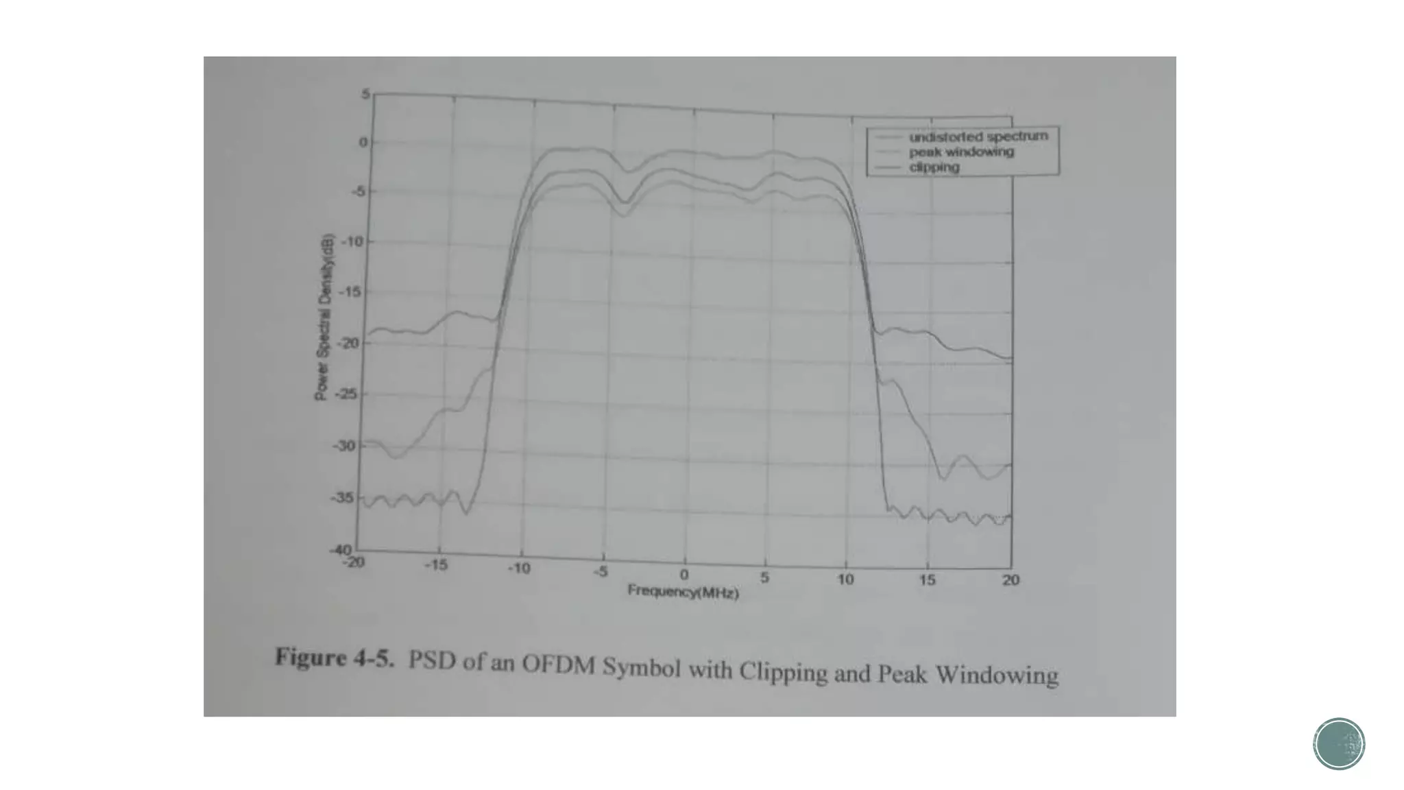
1. The document analyzes the effect of signal distortion techniques for PAPR reduction like clipping and peak windowing on the bit error rate (BER) performance of turbo and low density parity check (LDPC) coded orthogonal frequency division multiplexing (OFDM) systems.
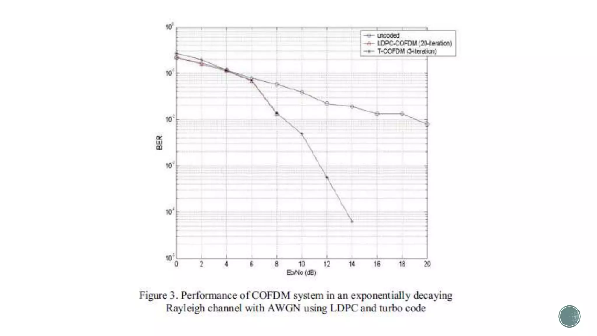
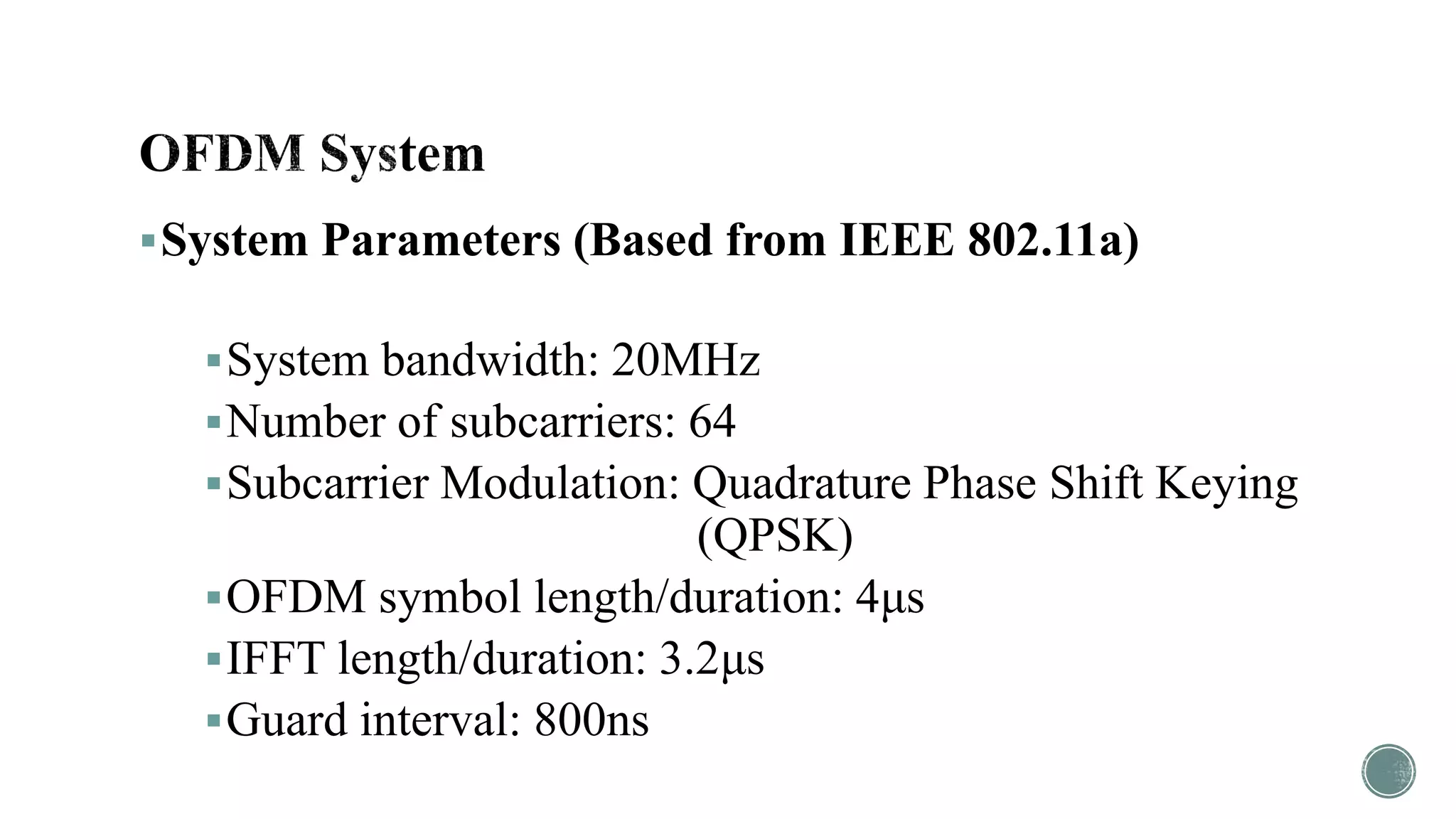
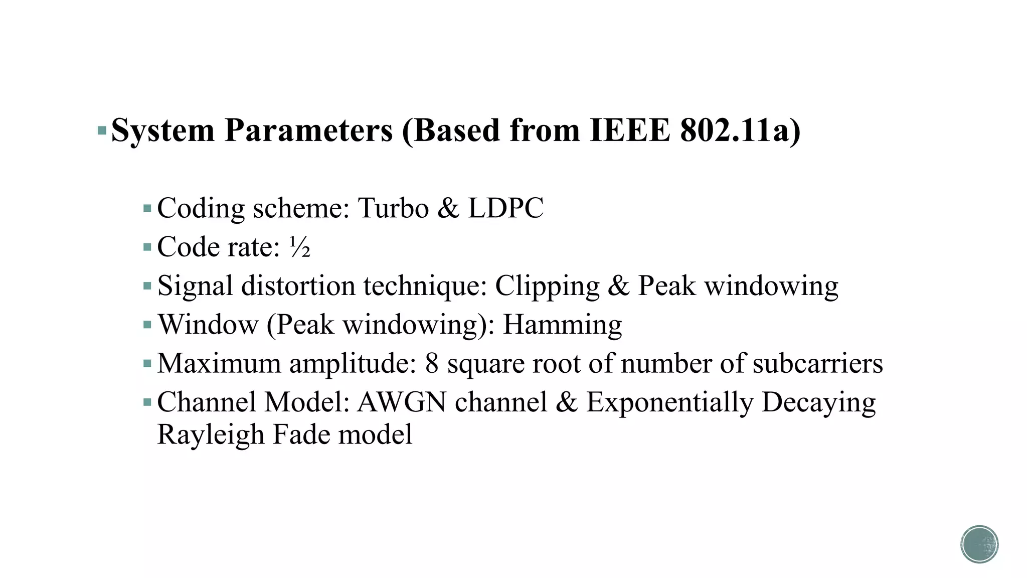
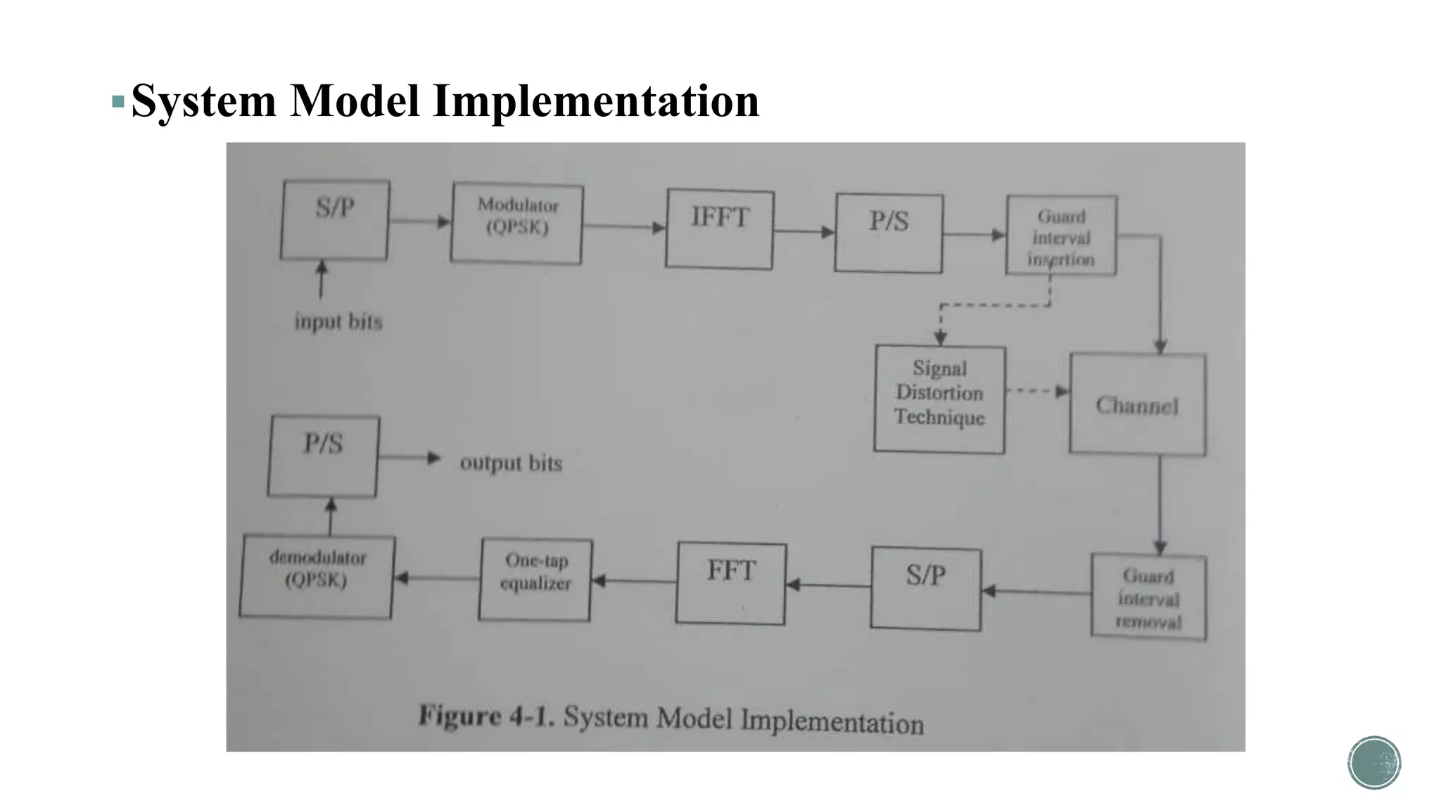
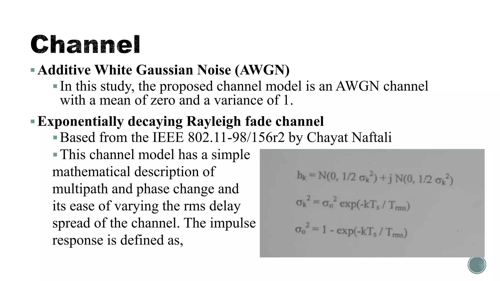
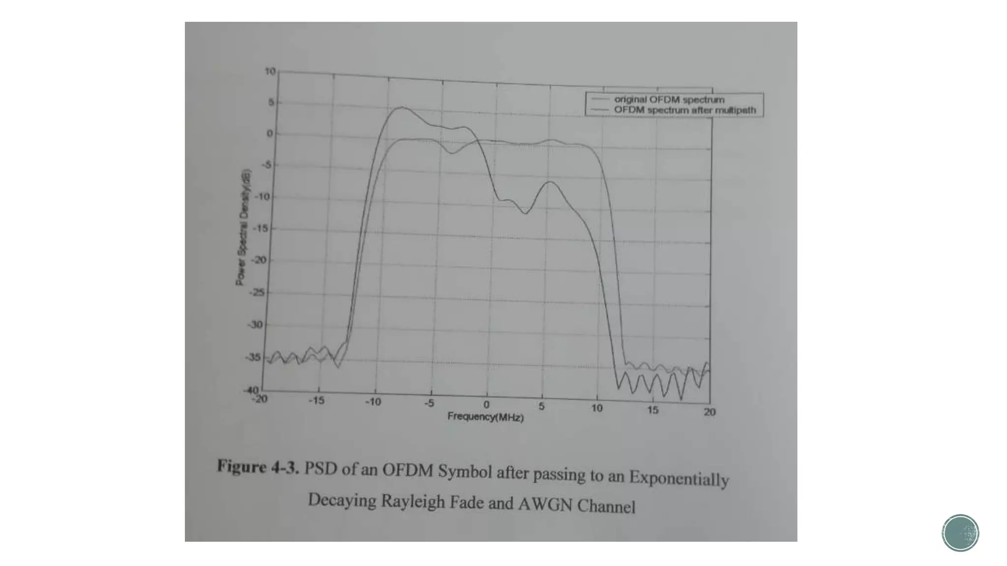
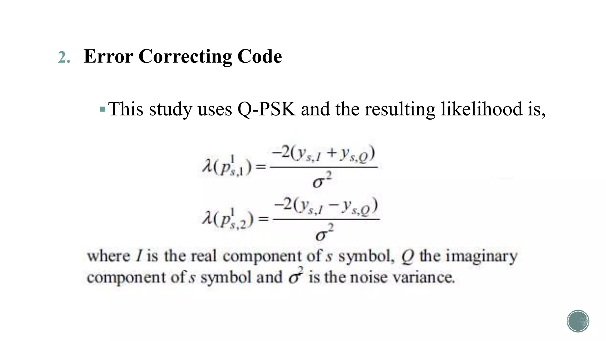
2. It implements an OFDM system based on IEEE 802.11a standards with turbo and LDPC error correcting codes over additive white Gaussian noise (AWGN) and exponentially decaying Rayleigh fade channels.
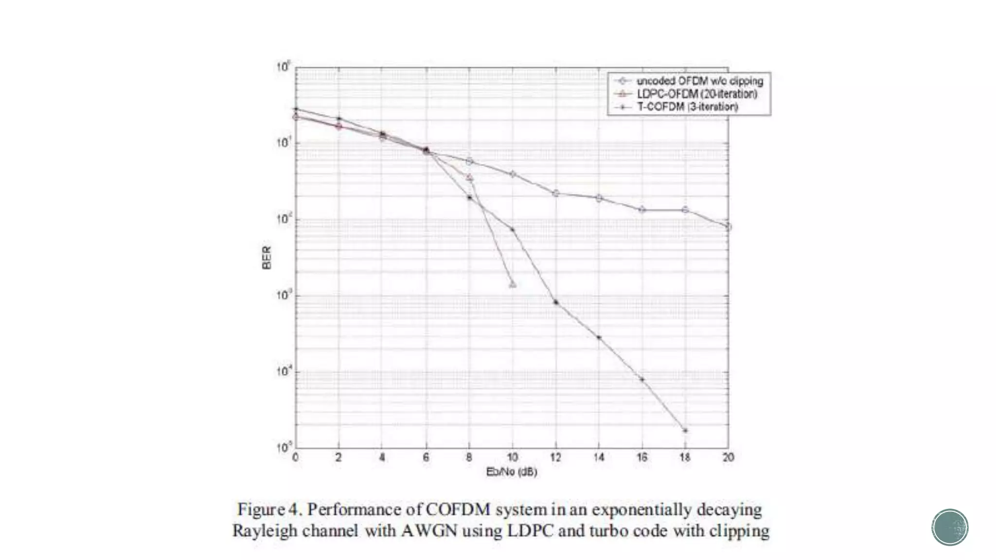
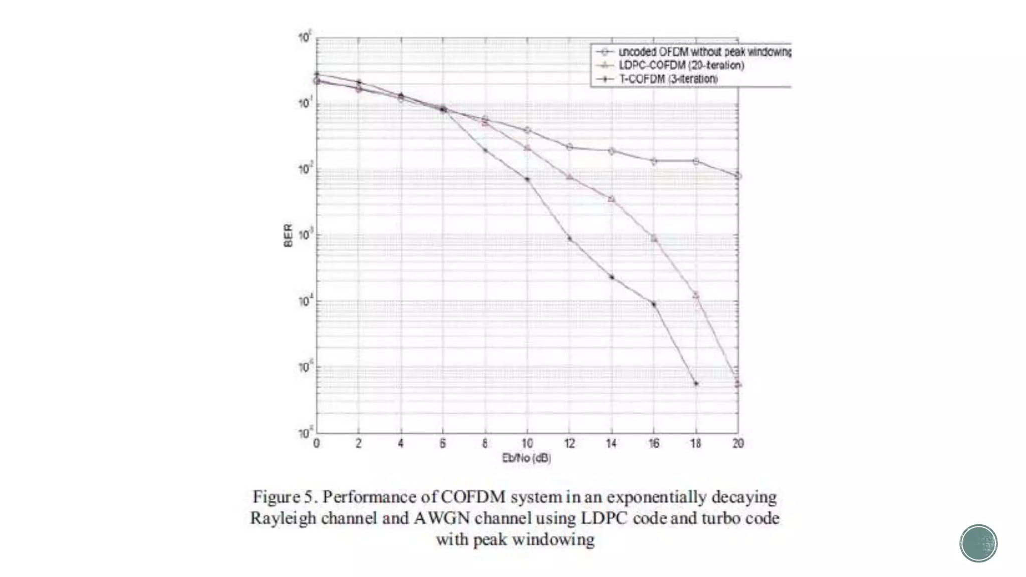
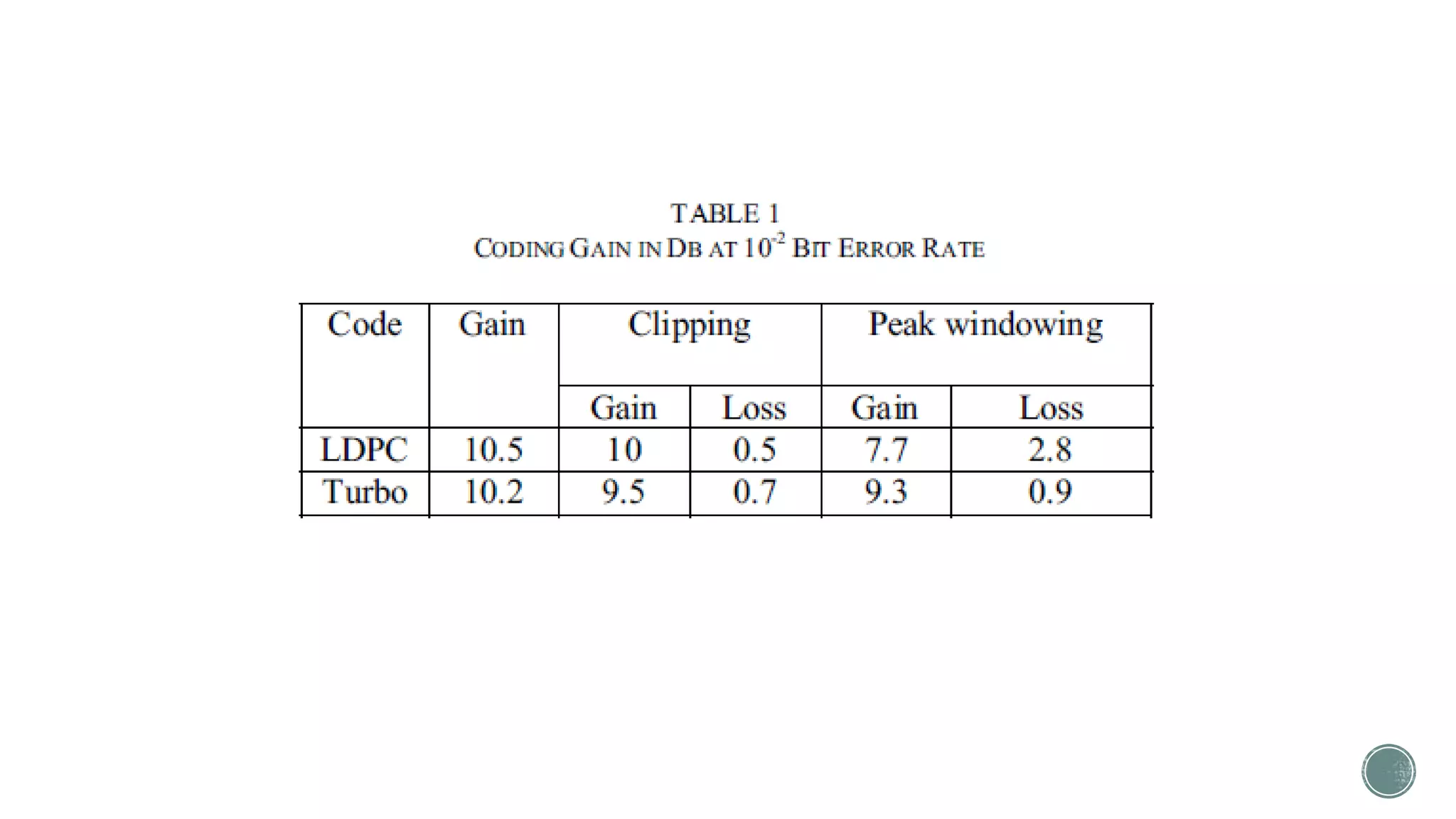
3. The results show that LDPC-COFDM performs better than turbo-COFDM in both channels, even with clipping applied. However, turbo-COFDM is better with peak windowing due to
![b) LDPC Code Encoder & Decoder
For the encoding, parity check matrix is used.
A 1104, 522 code with a characteristic of an irregular
LDPC Code.
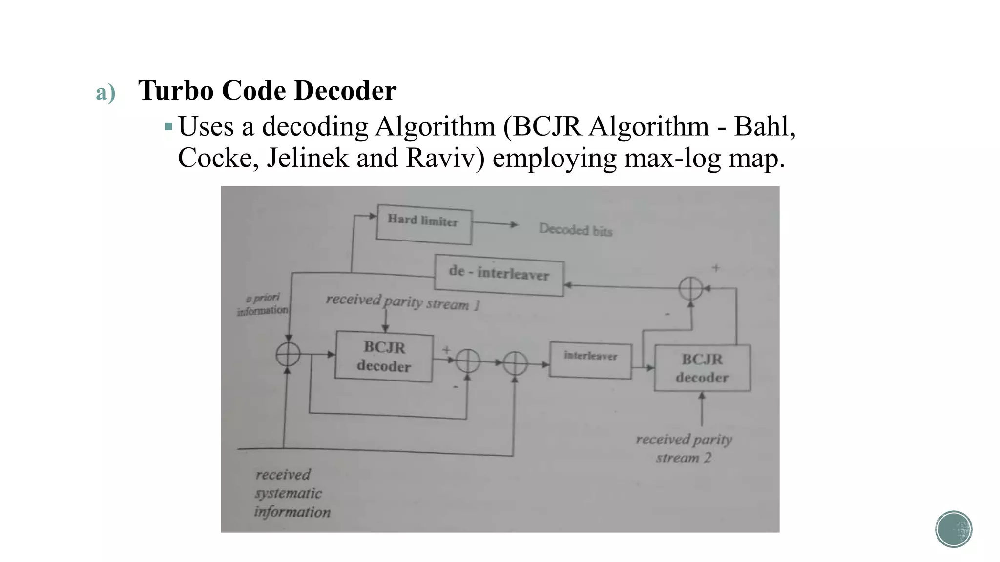
Uses a decoding algorithm that is based from belief
propagation.
The produced parity check matrix H=[A:B] was
rearranged so that A is non-singular.](https://image.slidesharecdn.com/wirelessreportonofdm-160830024447/75/Signal-Distortion-Techniques-for-PAPR-Reduction-in-OFDM-systems-27-2048.jpg)