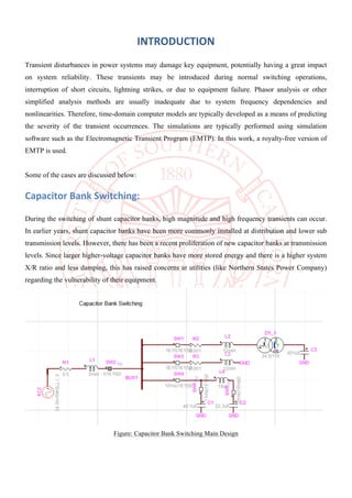
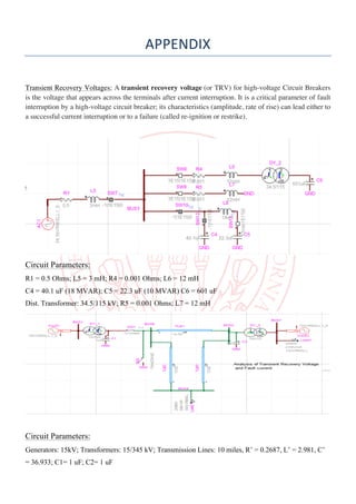
- The document analyzes various transient events in power systems using EMTP-RV simulation software, including capacitor bank switching, back-to-back switching, transformer switching, and transient recovery voltages.
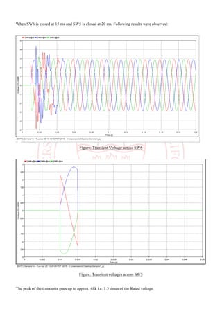
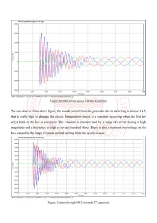
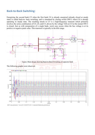
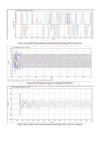
- Simulations of capacitor bank switching show transient overvoltages up to 1.5 times the rated voltage. Back-to-back capacitor switching results in high-frequency transients.
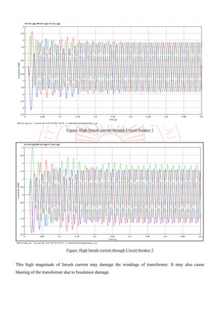
- Transformer switching simulations demonstrate high inrush currents that could damage windings or cause insulation failure without controlled switching.
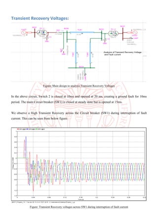
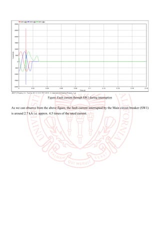
- Interrupting a ground fault by a circuit breaker leads to high transient recovery voltages that risk re-ignition if above breakdown thresholds.