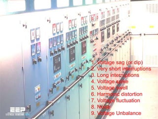
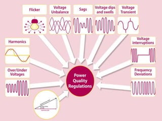
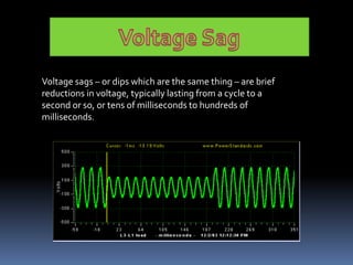
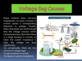
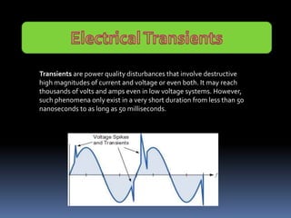
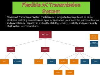
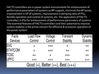
INTRODUCTION TO
POWER QUALITY
AND FACTS
Shivani Mishra
Lecturer (EN)
1. Voltage sag (or dip)
2. Very short interruptions
3. Long interruptions
4. Voltage spike
5. Voltage swell
6. Harmonic distortion
7. Voltage fluctuation
8. Noise
9. Voltage Unbalance
CBEMA CURVE
This standard specifies the minimum
withstanding capability of computer equip-
ment to voltage sags, micro-interruptions
and over-voltages.
Voltage sags – or dips which are the same thing – are brief
reductions in voltage, typically lasting from a cycle to a
second or so, or tens of milliseconds to hundreds of
milliseconds.
Power systems have non-zero
impedances, so every increase in
current causes a corresponding
reduction in voltage. Usually,
these reductions are small enough
that the voltage remains within
normal tolerances. But when there
is a large increase in current, or
when the system impedance is
high, the voltage can drop
significantly.
So conceptually, there are two
sources of voltage sags:-
•Large increases in current
•Increases in system impedance
Different mitigation methods are
o Dynamic voltage restorer
o Active series Compensators
o Distribution static compensator
(DSTATCOM) or Solid state transfer switch (SSTS)
o Static UPS with energy storage
o Backup storage energy supply (BSES) o Ferro
resonant transformer
o Flywheel and Motor Generator set
o Static Var Compensator (SVC)
DynamicVoltage Restorers
(DVR) are complicated static
devices which work by adding
the ‘missing’ voltage during a
voltage sag. Basically this
means that the device injects
voltage into the system in
order to bring the voltage back
up to the level required by the
load.
A Ferro resonant transformer, also
known as a constant voltage
transformer (CVT), is a transformer
that operates in the saturation region
of the transformer B-H curve.
Voltage sags down to 30 % retained
voltage can be mitigated through the
use of Ferro resonant transformers.
Transients are power quality disturbances that involve destructive
high magnitudes of current and voltage or even both. It may reach
thousands of volts and amps even in low voltage systems. However,
such phenomena only exist in a very short duration from less than 50
nanoseconds to as long as 50 milliseconds.
1. Lightning Strikes
2. Switching activities
· Opening and closing of disconnects onenergized lines
· Capacitor bank switching
· Reclosing operations
· Tap changing on transformers
3.Loose connections in the distribution system that results to
arcing Accidents, human error, animals and bad weather
conditions Neighboring facilities.
Sources ofTransients
Electronic Equipment
 Equipment will malfunction and produces corrupted results
 Improper specification and installation of TVSS can aggravate the failures
 Efficiency of electronic devices will be reduced
Motors
 Transients will make motors run at higher temperatures
 Result in micro-jogging leading to motor vibration, excessive heat and noise
 Degrades the insulation of the motor winding resulting to equipment failure.
 Increases the motor’s losses (hysteresis) and its operating temperature
Lights
 Fluorescent bulb and ballast failure
 Appearance of black rings at the fluorescent tube ends (indicator of transients)
 Premature filament damage leading to failure of the incandescent light.
Electrical Equipment
 Transients degrade the contacting surfaces of circuit breakers and switches
 Nuisance tripping of breakers due to false activation to a non-existent current demand
 Reduce transformer efficiency because of increased hysteresis losses
Flexible ACTransmission System (Facts) is a new integrated concept based on power
electronic switching converters and dynamic controllers to enhance the system utilization
and power transfer capacity as well as the stability, security, reliability and power quality
of AC system interconnections.
FACTS controllers are in power system environments for enhancement of
performance parameters of systems as RP support, minimize the AP losses,
improvement inVP of systems, improvement in damping ratio of PSs,
flexible operation and control of systems, etc. the application of FACTS
controllers in PSs for enhancement of performance parameters of systems.
The essential features of FACTS controllers and their potential to improve
system stability is the prime concern for effective & economic operation of
the power system.
(a) SVC. (b)TCVR. (c)TCSC. (d)TCPST. (e) UPFC.
The transmittable power of this system can be simply represented by
the
well–known equation below:-
where δ1and δ2are the angle of ˙
V1andV2. Assuming the magnitudes of the voltage at both
ends are invariant,
There are four main advantages to using FACTS -
1.Further exploit current transmission asset
2. Enhance the flexibility and reliability of current transmission systems
3. Reduce the loop flows.
4. Environmental benefits.
In an electric power system, a harmonic is a voltage or current at a
multiple of the fundamental frequency of the system, produced by
the action of non-linear loads such as rectifiers, discharge lighting,
or saturated magnetic devices.
Switch-mode power supplies (SMPS), variable speed
motors and drives, photocopiers, personal
computers, laser printers, fax machines, battery
chargers and UPSs are examples of nonlinear loads.
Single-phase non-linear loads are prevalent in
modern office buildings, while three-phase, non-
linear loads are widespread in factories and industrial
plants.
harmonics are distortion of the normal electrical
current waveform, generally transmitted by nonlinear
loads that draw a non sinusoidal current from a
sinusoidal voltage source.A harmonic current
increases power system heat losses, reduces system
efficiency. Harmonic currents can have a significant
impact on electrical distribution systems and the
facilities they feed.
Non linear Loads & Harmonics
THD (Total Harmonic Distortion)
A common term that is used in relation to harmonics isTHD orTotal
Harmonic Distortion.THD is a term used to describe the net deviation of
non-linear waveform from ideal sine waveform.Total Harmonic
Distortion is the ratio between the RMS values of the harmonics and the
RMS value of fundamental.
• Large load currents in the neutral wires of a 3 phase system.
• High neutral-to-ground voltage often greater than 2 volts
• communication errors, overheating and hardware damage
• Overheating of electrical distribution equipment, cables, transformers, standby
generators, etc.
• High voltages and circulating currents caused by harmonic resonance
• Generator Hunting
• ElectronicControl Clock errors
• Quivering Monitors and CRT displays
• Equipment malfunctions due to excessive voltage distortion
• Nuisance tripping of circuit breakers
• Metering errors needs true metering
• zero-crossing noise
• skin effect
• Reducing system power factor, resulting in penalties on monthly utility bills
overloading of neutrals
1. Line reactor
2. Isolation transformer
3. K-factor transformer
4. Tuned harmonic filter
5. IGBT based fast switched harmonic
filter
6. Low pass harmonic filter
7. 12 & 18 pulse rectifier
8. Phase shifting transformer
9. Active harmonic filters
Ppt on introduction to power quality

Ppt on introduction to power quality

  • 1.
    INTRODUCTION TO POWER QUALITY ANDFACTS Shivani Mishra Lecturer (EN)
  • 2.
    1. Voltage sag(or dip) 2. Very short interruptions 3. Long interruptions 4. Voltage spike 5. Voltage swell 6. Harmonic distortion 7. Voltage fluctuation 8. Noise 9. Voltage Unbalance
  • 4.
    CBEMA CURVE This standardspecifies the minimum withstanding capability of computer equip- ment to voltage sags, micro-interruptions and over-voltages.
  • 7.
    Voltage sags –or dips which are the same thing – are brief reductions in voltage, typically lasting from a cycle to a second or so, or tens of milliseconds to hundreds of milliseconds.
  • 8.
    Power systems havenon-zero impedances, so every increase in current causes a corresponding reduction in voltage. Usually, these reductions are small enough that the voltage remains within normal tolerances. But when there is a large increase in current, or when the system impedance is high, the voltage can drop significantly. So conceptually, there are two sources of voltage sags:- •Large increases in current •Increases in system impedance
  • 9.
    Different mitigation methodsare o Dynamic voltage restorer o Active series Compensators o Distribution static compensator (DSTATCOM) or Solid state transfer switch (SSTS) o Static UPS with energy storage o Backup storage energy supply (BSES) o Ferro resonant transformer o Flywheel and Motor Generator set o Static Var Compensator (SVC)
  • 10.
    DynamicVoltage Restorers (DVR) arecomplicated static devices which work by adding the ‘missing’ voltage during a voltage sag. Basically this means that the device injects voltage into the system in order to bring the voltage back up to the level required by the load. A Ferro resonant transformer, also known as a constant voltage transformer (CVT), is a transformer that operates in the saturation region of the transformer B-H curve. Voltage sags down to 30 % retained voltage can be mitigated through the use of Ferro resonant transformers.
  • 11.
    Transients are powerquality disturbances that involve destructive high magnitudes of current and voltage or even both. It may reach thousands of volts and amps even in low voltage systems. However, such phenomena only exist in a very short duration from less than 50 nanoseconds to as long as 50 milliseconds.
  • 12.
    1. Lightning Strikes 2.Switching activities · Opening and closing of disconnects onenergized lines · Capacitor bank switching · Reclosing operations · Tap changing on transformers 3.Loose connections in the distribution system that results to arcing Accidents, human error, animals and bad weather conditions Neighboring facilities. Sources ofTransients
  • 13.
    Electronic Equipment  Equipmentwill malfunction and produces corrupted results  Improper specification and installation of TVSS can aggravate the failures  Efficiency of electronic devices will be reduced Motors  Transients will make motors run at higher temperatures  Result in micro-jogging leading to motor vibration, excessive heat and noise  Degrades the insulation of the motor winding resulting to equipment failure.  Increases the motor’s losses (hysteresis) and its operating temperature Lights  Fluorescent bulb and ballast failure  Appearance of black rings at the fluorescent tube ends (indicator of transients)  Premature filament damage leading to failure of the incandescent light. Electrical Equipment  Transients degrade the contacting surfaces of circuit breakers and switches  Nuisance tripping of breakers due to false activation to a non-existent current demand  Reduce transformer efficiency because of increased hysteresis losses
  • 14.
    Flexible ACTransmission System(Facts) is a new integrated concept based on power electronic switching converters and dynamic controllers to enhance the system utilization and power transfer capacity as well as the stability, security, reliability and power quality of AC system interconnections.
  • 15.
    FACTS controllers arein power system environments for enhancement of performance parameters of systems as RP support, minimize the AP losses, improvement inVP of systems, improvement in damping ratio of PSs, flexible operation and control of systems, etc. the application of FACTS controllers in PSs for enhancement of performance parameters of systems. The essential features of FACTS controllers and their potential to improve system stability is the prime concern for effective & economic operation of the power system.
  • 16.
    (a) SVC. (b)TCVR.(c)TCSC. (d)TCPST. (e) UPFC.
  • 17.
    The transmittable powerof this system can be simply represented by the well–known equation below:- where δ1and δ2are the angle of ˙ V1andV2. Assuming the magnitudes of the voltage at both ends are invariant, There are four main advantages to using FACTS - 1.Further exploit current transmission asset 2. Enhance the flexibility and reliability of current transmission systems 3. Reduce the loop flows. 4. Environmental benefits.
  • 18.
    In an electricpower system, a harmonic is a voltage or current at a multiple of the fundamental frequency of the system, produced by the action of non-linear loads such as rectifiers, discharge lighting, or saturated magnetic devices.
  • 19.
    Switch-mode power supplies(SMPS), variable speed motors and drives, photocopiers, personal computers, laser printers, fax machines, battery chargers and UPSs are examples of nonlinear loads. Single-phase non-linear loads are prevalent in modern office buildings, while three-phase, non- linear loads are widespread in factories and industrial plants. harmonics are distortion of the normal electrical current waveform, generally transmitted by nonlinear loads that draw a non sinusoidal current from a sinusoidal voltage source.A harmonic current increases power system heat losses, reduces system efficiency. Harmonic currents can have a significant impact on electrical distribution systems and the facilities they feed. Non linear Loads & Harmonics
  • 20.
    THD (Total HarmonicDistortion) A common term that is used in relation to harmonics isTHD orTotal Harmonic Distortion.THD is a term used to describe the net deviation of non-linear waveform from ideal sine waveform.Total Harmonic Distortion is the ratio between the RMS values of the harmonics and the RMS value of fundamental.
  • 21.
    • Large loadcurrents in the neutral wires of a 3 phase system. • High neutral-to-ground voltage often greater than 2 volts • communication errors, overheating and hardware damage • Overheating of electrical distribution equipment, cables, transformers, standby generators, etc. • High voltages and circulating currents caused by harmonic resonance • Generator Hunting • ElectronicControl Clock errors • Quivering Monitors and CRT displays • Equipment malfunctions due to excessive voltage distortion • Nuisance tripping of circuit breakers • Metering errors needs true metering • zero-crossing noise • skin effect • Reducing system power factor, resulting in penalties on monthly utility bills overloading of neutrals
  • 22.
    1. Line reactor 2.Isolation transformer 3. K-factor transformer 4. Tuned harmonic filter 5. IGBT based fast switched harmonic filter 6. Low pass harmonic filter 7. 12 & 18 pulse rectifier 8. Phase shifting transformer 9. Active harmonic filters