SlideShare a Scribd company logo
Application
Engine cooling system (radiators)
Radiators are required for the cooling of internal combustion
engines. They operate by passing a liquid coolant through the engine
block, where it is heated, then through the radiator where it loses the
heat to the atmosphere. The coolant is generally water (with some
additives, e.g. anti-freezing agents, corrosion inhibitors, etc.). Usually
the coolant is circulated by means of a pump and a fan is used to blow
air through the radiator
Configuration of radiator (schematic)
Detail element of the radiator
In general, the radiator consists of the aluminium radiator core and
two header tanks that cover the ends of the radiator and all of the
required connections and fastening elements. The header tanks allow
for the appropriate coolant volume to be circulated through the
tubes. The radiator core is usually made of flattened aluminium tubes
(although multiport extrusions can also be used) and aluminium fins
that zigzag between the tubes. These fins transfer the heat in the
tubes into the air stream to be carried away from the vehicle.
On most modern radiators, the tubes run horizontally with the
header tanks on either side. But the tubes may also run vertically
with the tanks on top and bottom. There are gaskets between the
aluminium core and the header tanks to seal the system and to keep
the coolant from leaking out. The header tanks are generally made of
plastic (e.g. fibre glass-reinforced polyamide), but there are also all-
aluminium radiators. All-aluminium radiators are lighter than the
versions with plastic tanks, have a much smaller packaging depth,
and are fully recyclable.
Simple brazed aluminium radiator with plastic tank
On older vehicles, the radiator core was made of copper and the
tanks were brass. The brass tanks were brazed to the copper core in
order to seal the radiator. The modern aluminium radiator systems
are much more efficient and durable, not to mention cheaper to
produce.
Oil coolers
Oil coolers (and warming systems) are necessary to keep the
temperature of the oil, needed for he functioning of the engine and
other automotive systems under control. In highly stressed engines
the engine oil has to be cooled. Vehicles with automatic
transmissions and highly stressed manual transmissions require
transmission oil coolers. In fact there may be also heat exchangers for
cooling the oil of the power steering, the hydraulic components for
brakes and absorbing systems for improving the driving comfort, etc.,
in a car.
Oil cooling raises the viscosity and hence the oil lubricating power.
Thus the oil change intervals are prolonged and the protection of the
mechanical parts against wear, etc., is improved.
Oil cooling can be accomplished by air-
cooled heat exchangers or coolant-based
oil coolers (i.e. the coolant in the engine
cooling circuit). The latter involves
simplified oil circuits and lower cost if
compared to the oil-air solutions which
offer higher performances and do not
lead to an additional thermal load for the
radiator. Air-cooled oil cooler are
generally positioned in the cooling air
flow in cars and equipped with an
additional fan. Coolant-cooled oil coolers can be incorporated in the
coolant tank or engine block, or fitted externally on the engine,
transmission, cooling module, or oil filter housing, as required.
Oil coolers are produced in a large variety of designs. Due to the
typical service conditions in terms of pressure (up to 15 bar) and
temperature (up to 150 °C), they cannot be mechanically assembled,
but must be brazed. The main material requirements are pressure
resistance (i.e. strength, also at elevated temperature) and corrosion
resistance.
Brazed liquid-to-liquid oil cooler Power steering oil cooler
3 Heater cores
The hot engine coolant is used to provide heat to the interior of the
vehicle when needed. This is a simple and straight forward system
that includes a heater core which is connected to the cooling system
with a pair of rubber hoses. One hose brings hot coolant from the
water pump to the heater core and the other hose returns the coolant
to the top of the engine.
The All-aluminium heater core
The heater core is a small radiator like device which is usually
mounted under the dash board or if the car is equipped with an air
conditioning system - in the HVAC housing.
The coolant flow through the heater core is controlled by a heater
control valve. A fan blows outside air through the heater core and
directs the heat into the inside of the automobile. The temperature of
the heated air is regulated by a blend door that mixes cool outside
air. In an air conditioning system, the heater core reheats a portion of
the air cooled by the evaporator by exchanging heat with engine-
cooling water. The reheated air is then mixed with the remaining
evaporator-cooled air and the mixed air is blown into the vehicle
cabin.
Schematic drawing of a typical heater core assembly
The heater core consists of an assembly of tube sand fins with tanks
on both sides. One of the tanks, made either from aluminium or
plastic, is fitted with inlet and outlet tubes. The heater cores are
today mainly brazed (generally by controlled atmosphere brazing),
but could also be mechanically assembled. Subsequently the tanks
are crimped to the headers.
4. Air conditioning
The air conditioning system is used for the following purposes:
 temperature control
 air circulation control
 humidity control
 Air purification.
If the car is equipped with air conditioning, the heater core is
integrated with the air conditioning system into a single-unit.
General considerations
Automotive air conditioning is similar to stationary air conditioning
in the sense that it also requires the cyclic flow of the refrigerant
through an evaporator to absorb the heat and dissipating that in the
condenser. However, automotive air conditioning faces several
additional challenges:
 temperature parameters involved with the evaporator and
condenser
 variable air flow characteristics within the system
 variable compressor speed (depending on engine speed)
 Variable air flow through the condenser (related to the vehicle
speed).
The last two variables not only differentiate vehicle air conditioning
from stationary types of air conditioning, but are also very
demanding requirements. Package limitations, high demands on fuel
efficiency and pollution control place additional stringent
requirements on the design of air conditioning systems.
A blower unit, a heating unit and a cooling unit are the main
components of automobile air conditioning system. The cooling unit
in turn consists of an evaporator, compressor, condenser and an
expansion valve and the attached control systems. The heating unit
consists of a heater core and the associated control mechanisms.
In the cooling unit, a suitable refrigerant enters the evaporator, picks
up the heat from the air and becomes vapour. The vapour is then
compressed by the compressor and the compressed vapour enters
into the condenser where the hot compressed vapour is cooled and
further condensed, i.e. the vapour to liquid phase transformation
takes place.
The excess heat is transferred by the condenser to the outside air.
The liquid refrigerant passes through an expansion valve before it is
returned into the evaporator.
Condenser
If the car has air conditioning, there is an additional heat exchanger
called the air conditioner condenser, which also needs to be cooled
by the air flow entering the engine compartment. Its location is
usually in front of the radiator, but in some cases, due to
aerodynamic improvements to the body of a vehicle, its location may
differ. Condensers must have good air flow anytime the system is in
operation.
By exchanging heat with air, the condenser cools the high
temperature; high-pressure gas refrigerant sent from the compressor
and condenses it into liquid refrigerant. This heat exchange allows
the air conditioning system to emit the heat absorbed by the
evaporator from inside the vehicle to the outside.
In the condenser, the refrigerant (today R-134a) is circulating with a
high-pressure range (maximum about 20 bar). The normal operating
temperature ranges from room temperature up to 35 – 40 °C. The
main tube material requirements are:
 Pressure resistance (i.e. adequate strength)
 Sag resistance (stability during brazing)
 Corrosion resistance.
As for all heat exchangers, in terms of performance, condensers must
ensure maximum heat transfer while keeping size to a minimum.
Furthermore, condensers must be of an extremely high quality,
providing trouble-free performance throughout its service life at low
manufacturing costs.
Typically air conditioning condensers are of either of the parallel
flow or of the serpentine type design. A very small fraction of
condenser designs are based on mechanically assembled solutions.
Practically all condensers are produced by brazing (in general using
the controlled atmosphere brazing method).
Heat Exchangers – always there where they’re needed Wherever
heat or cold are transferred in building services engineering – we
offer the optimum plate heat exchangers for your application.
District heating stations Cooling water system separation
 Oil cooling
 Solar system separation
 Combined heat and
power
 station system separation
 Swimming pools
 Heat pumps
 Process water
 heating/cooling
 Under floor heating
 Emulsion cooling
 Geothermic
 Districtcooling
Application

More Related Content

What's hot

Chapter 2 cooling system
Chapter 2   cooling systemChapter 2   cooling system
Chapter 2 cooling system
Hafizkamaruddin
 
Engine cooling system by Indranil Mandal
Engine cooling system by Indranil MandalEngine cooling system by Indranil Mandal
Engine cooling system by Indranil Mandal
IndranilMandal
 
Cooling system
Cooling systemCooling system
Cooling system
Shahrul Nizam
 
Cooling systems
Cooling systemsCooling systems
Cooling systems
Andy Tabberer-Catt
 
Cooling system in i.c. engine
Cooling system in i.c. engineCooling system in i.c. engine
Cooling system in i.c. engine
BGMEA University of Fashion & Technology
 
Cooling system
Cooling systemCooling system
Cooling system
Megharaj Madke
 
Report of Engine Cooling & Exhaust System
Report of Engine Cooling & Exhaust SystemReport of Engine Cooling & Exhaust System
Report of Engine Cooling & Exhaust System
Mal Mai
 
Halderman ch021 lecture
Halderman ch021 lectureHalderman ch021 lecture
Halderman ch021 lecturemcfalltj
 
Cooling system in Automobiles
Cooling system in AutomobilesCooling system in Automobiles
Cooling system in Automobiles
Harpreet Singh
 
What is Engine Cooling System
What is Engine Cooling SystemWhat is Engine Cooling System
What is Engine Cooling System
payalkataria01
 
Cooling system ppt
Cooling system pptCooling system ppt
Cooling system ppt
AKTU LUCKNOW
 
Automobile
AutomobileAutomobile
Automobile
manojmug345
 
Renewable energy sources
Renewable energy sources Renewable energy sources
Renewable energy sources
Surendra Patait
 
Cooling System Principles
Cooling System PrinciplesCooling System Principles
Cooling System Principles
John Parman
 
Cooling system
Cooling systemCooling system
Cooling systemAjay Yadav
 
Engine cooling system
Engine cooling systemEngine cooling system
Engine cooling system
yajurvendra tomar
 
Cooling system
Cooling systemCooling system
Cooling system
suyogbalankar
 
Cooling system
Cooling systemCooling system
Cooling system
nitesh anjane
 
Cooling system
Cooling systemCooling system
Cooling system
Mantosh Kumar
 
Fuel injection system for si engines
Fuel injection system for si enginesFuel injection system for si engines
Fuel injection system for si engines
Manas Pandey
 

What's hot (20)

Chapter 2 cooling system
Chapter 2   cooling systemChapter 2   cooling system
Chapter 2 cooling system
 
Engine cooling system by Indranil Mandal
Engine cooling system by Indranil MandalEngine cooling system by Indranil Mandal
Engine cooling system by Indranil Mandal
 
Cooling system
Cooling systemCooling system
Cooling system
 
Cooling systems
Cooling systemsCooling systems
Cooling systems
 
Cooling system in i.c. engine
Cooling system in i.c. engineCooling system in i.c. engine
Cooling system in i.c. engine
 
Cooling system
Cooling systemCooling system
Cooling system
 
Report of Engine Cooling & Exhaust System
Report of Engine Cooling & Exhaust SystemReport of Engine Cooling & Exhaust System
Report of Engine Cooling & Exhaust System
 
Halderman ch021 lecture
Halderman ch021 lectureHalderman ch021 lecture
Halderman ch021 lecture
 
Cooling system in Automobiles
Cooling system in AutomobilesCooling system in Automobiles
Cooling system in Automobiles
 
What is Engine Cooling System
What is Engine Cooling SystemWhat is Engine Cooling System
What is Engine Cooling System
 
Cooling system ppt
Cooling system pptCooling system ppt
Cooling system ppt
 
Automobile
AutomobileAutomobile
Automobile
 
Renewable energy sources
Renewable energy sources Renewable energy sources
Renewable energy sources
 
Cooling System Principles
Cooling System PrinciplesCooling System Principles
Cooling System Principles
 
Cooling system
Cooling systemCooling system
Cooling system
 
Engine cooling system
Engine cooling systemEngine cooling system
Engine cooling system
 
Cooling system
Cooling systemCooling system
Cooling system
 
Cooling system
Cooling systemCooling system
Cooling system
 
Cooling system
Cooling systemCooling system
Cooling system
 
Fuel injection system for si engines
Fuel injection system for si enginesFuel injection system for si engines
Fuel injection system for si engines
 

Similar to Application

Cooling System - IC Engines : Unit-III
Cooling System - IC Engines : Unit-IIICooling System - IC Engines : Unit-III
Cooling System - IC Engines : Unit-III
S.Vijaya Bhaskar
 
IC Engines lubrication & cooling methods
IC Engines lubrication & cooling methodsIC Engines lubrication & cooling methods
IC Engines lubrication & cooling methods
vinodh32
 
cooling and lubrication system
cooling and lubrication systemcooling and lubrication system
cooling and lubrication system
naphis ahamad
 
Engine Cooling system
Engine Cooling systemEngine Cooling system
Engine Cooling system
kaushal gadariya
 
Cooling system in i.c engine
Cooling system in i.c engineCooling system in i.c engine
Cooling system in i.c engine
fadwala07
 
Presentation on automobile hvac system
Presentation  on automobile hvac systemPresentation  on automobile hvac system
Presentation on automobile hvac system
kartik Bhardwaj
 
cooling system in ic engine
cooling system in ic enginecooling system in ic engine
cooling system in ic engine
pradipsinh jadeja
 
Car Air condition cycle.ppt
Car Air condition cycle.pptCar Air condition cycle.ppt
Car Air condition cycle.ppt
HaroonMurshed
 
Recovery of Engine Waste Heat for Reutilization in Air Conditioning System in...
Recovery of Engine Waste Heat for Reutilization in Air Conditioning System in...Recovery of Engine Waste Heat for Reutilization in Air Conditioning System in...
Recovery of Engine Waste Heat for Reutilization in Air Conditioning System in...Joel John
 
SYSTEMS OF IC ENGINE- Cooling System.pptx
SYSTEMS OF IC ENGINE- Cooling System.pptxSYSTEMS OF IC ENGINE- Cooling System.pptx
SYSTEMS OF IC ENGINE- Cooling System.pptx
Ajay Singh Lodhi
 
Cooling system
Cooling systemCooling system
Cooling system
munir sharif
 
Cooling system in cars engines
Cooling system in cars engines Cooling system in cars engines
Cooling system in cars engines
MahdiKarim6
 
Heat transfer analysis in Automobiles
Heat transfer analysis in AutomobilesHeat transfer analysis in Automobiles
Heat transfer analysis in Automobiles
kanhaiya123654
 
Methods of Cooling.pptx
Methods of Cooling.pptxMethods of Cooling.pptx
Methods of Cooling.pptx
naseeruddinshah2
 
Chapter 20
Chapter 20Chapter 20
Chapter 20mcfalltj
 
Chapter 20
Chapter 20Chapter 20
Chapter 20mcfalltj
 
Hydrogen in power plants
Hydrogen in power plantsHydrogen in power plants
Hydrogen in power plants
Yogendra Sharma
 
Cooling system for ic engines
Cooling system for ic engines Cooling system for ic engines
Cooling system for ic engines sgrsoni45
 
ENERGY AUDIT presentationin power system .pptx
ENERGY AUDIT presentationin power system .pptxENERGY AUDIT presentationin power system .pptx
ENERGY AUDIT presentationin power system .pptx
ReshevSharma
 
2 Cooling System Theory.ppt
2 Cooling System Theory.ppt2 Cooling System Theory.ppt
2 Cooling System Theory.ppt
AbhishekChavan77
 

Similar to Application (20)

Cooling System - IC Engines : Unit-III
Cooling System - IC Engines : Unit-IIICooling System - IC Engines : Unit-III
Cooling System - IC Engines : Unit-III
 
IC Engines lubrication & cooling methods
IC Engines lubrication & cooling methodsIC Engines lubrication & cooling methods
IC Engines lubrication & cooling methods
 
cooling and lubrication system
cooling and lubrication systemcooling and lubrication system
cooling and lubrication system
 
Engine Cooling system
Engine Cooling systemEngine Cooling system
Engine Cooling system
 
Cooling system in i.c engine
Cooling system in i.c engineCooling system in i.c engine
Cooling system in i.c engine
 
Presentation on automobile hvac system
Presentation  on automobile hvac systemPresentation  on automobile hvac system
Presentation on automobile hvac system
 
cooling system in ic engine
cooling system in ic enginecooling system in ic engine
cooling system in ic engine
 
Car Air condition cycle.ppt
Car Air condition cycle.pptCar Air condition cycle.ppt
Car Air condition cycle.ppt
 
Recovery of Engine Waste Heat for Reutilization in Air Conditioning System in...
Recovery of Engine Waste Heat for Reutilization in Air Conditioning System in...Recovery of Engine Waste Heat for Reutilization in Air Conditioning System in...
Recovery of Engine Waste Heat for Reutilization in Air Conditioning System in...
 
SYSTEMS OF IC ENGINE- Cooling System.pptx
SYSTEMS OF IC ENGINE- Cooling System.pptxSYSTEMS OF IC ENGINE- Cooling System.pptx
SYSTEMS OF IC ENGINE- Cooling System.pptx
 
Cooling system
Cooling systemCooling system
Cooling system
 
Cooling system in cars engines
Cooling system in cars engines Cooling system in cars engines
Cooling system in cars engines
 
Heat transfer analysis in Automobiles
Heat transfer analysis in AutomobilesHeat transfer analysis in Automobiles
Heat transfer analysis in Automobiles
 
Methods of Cooling.pptx
Methods of Cooling.pptxMethods of Cooling.pptx
Methods of Cooling.pptx
 
Chapter 20
Chapter 20Chapter 20
Chapter 20
 
Chapter 20
Chapter 20Chapter 20
Chapter 20
 
Hydrogen in power plants
Hydrogen in power plantsHydrogen in power plants
Hydrogen in power plants
 
Cooling system for ic engines
Cooling system for ic engines Cooling system for ic engines
Cooling system for ic engines
 
ENERGY AUDIT presentationin power system .pptx
ENERGY AUDIT presentationin power system .pptxENERGY AUDIT presentationin power system .pptx
ENERGY AUDIT presentationin power system .pptx
 
2 Cooling System Theory.ppt
2 Cooling System Theory.ppt2 Cooling System Theory.ppt
2 Cooling System Theory.ppt
 

Application

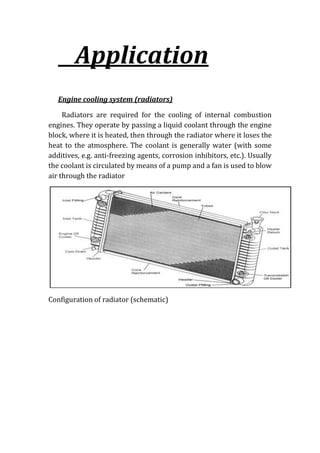
  • 1. Application Engine cooling system (radiators) Radiators are required for the cooling of internal combustion engines. They operate by passing a liquid coolant through the engine block, where it is heated, then through the radiator where it loses the heat to the atmosphere. The coolant is generally water (with some additives, e.g. anti-freezing agents, corrosion inhibitors, etc.). Usually the coolant is circulated by means of a pump and a fan is used to blow air through the radiator Configuration of radiator (schematic)
  • 2. Detail element of the radiator In general, the radiator consists of the aluminium radiator core and two header tanks that cover the ends of the radiator and all of the required connections and fastening elements. The header tanks allow for the appropriate coolant volume to be circulated through the tubes. The radiator core is usually made of flattened aluminium tubes (although multiport extrusions can also be used) and aluminium fins that zigzag between the tubes. These fins transfer the heat in the tubes into the air stream to be carried away from the vehicle. On most modern radiators, the tubes run horizontally with the header tanks on either side. But the tubes may also run vertically with the tanks on top and bottom. There are gaskets between the aluminium core and the header tanks to seal the system and to keep the coolant from leaking out. The header tanks are generally made of plastic (e.g. fibre glass-reinforced polyamide), but there are also all- aluminium radiators. All-aluminium radiators are lighter than the versions with plastic tanks, have a much smaller packaging depth, and are fully recyclable.
  • 3. Simple brazed aluminium radiator with plastic tank On older vehicles, the radiator core was made of copper and the tanks were brass. The brass tanks were brazed to the copper core in order to seal the radiator. The modern aluminium radiator systems are much more efficient and durable, not to mention cheaper to produce. Oil coolers Oil coolers (and warming systems) are necessary to keep the temperature of the oil, needed for he functioning of the engine and other automotive systems under control. In highly stressed engines the engine oil has to be cooled. Vehicles with automatic transmissions and highly stressed manual transmissions require transmission oil coolers. In fact there may be also heat exchangers for cooling the oil of the power steering, the hydraulic components for brakes and absorbing systems for improving the driving comfort, etc., in a car. Oil cooling raises the viscosity and hence the oil lubricating power. Thus the oil change intervals are prolonged and the protection of the mechanical parts against wear, etc., is improved.
  • 4. Oil cooling can be accomplished by air- cooled heat exchangers or coolant-based oil coolers (i.e. the coolant in the engine cooling circuit). The latter involves simplified oil circuits and lower cost if compared to the oil-air solutions which offer higher performances and do not lead to an additional thermal load for the radiator. Air-cooled oil cooler are generally positioned in the cooling air flow in cars and equipped with an additional fan. Coolant-cooled oil coolers can be incorporated in the coolant tank or engine block, or fitted externally on the engine, transmission, cooling module, or oil filter housing, as required. Oil coolers are produced in a large variety of designs. Due to the typical service conditions in terms of pressure (up to 15 bar) and temperature (up to 150 °C), they cannot be mechanically assembled, but must be brazed. The main material requirements are pressure resistance (i.e. strength, also at elevated temperature) and corrosion resistance. Brazed liquid-to-liquid oil cooler Power steering oil cooler 3 Heater cores
  • 5. The hot engine coolant is used to provide heat to the interior of the vehicle when needed. This is a simple and straight forward system that includes a heater core which is connected to the cooling system with a pair of rubber hoses. One hose brings hot coolant from the water pump to the heater core and the other hose returns the coolant to the top of the engine. The All-aluminium heater core The heater core is a small radiator like device which is usually mounted under the dash board or if the car is equipped with an air conditioning system - in the HVAC housing. The coolant flow through the heater core is controlled by a heater control valve. A fan blows outside air through the heater core and directs the heat into the inside of the automobile. The temperature of the heated air is regulated by a blend door that mixes cool outside air. In an air conditioning system, the heater core reheats a portion of the air cooled by the evaporator by exchanging heat with engine- cooling water. The reheated air is then mixed with the remaining evaporator-cooled air and the mixed air is blown into the vehicle cabin.
  • 6. Schematic drawing of a typical heater core assembly The heater core consists of an assembly of tube sand fins with tanks on both sides. One of the tanks, made either from aluminium or plastic, is fitted with inlet and outlet tubes. The heater cores are today mainly brazed (generally by controlled atmosphere brazing), but could also be mechanically assembled. Subsequently the tanks are crimped to the headers. 4. Air conditioning The air conditioning system is used for the following purposes:  temperature control  air circulation control  humidity control  Air purification. If the car is equipped with air conditioning, the heater core is integrated with the air conditioning system into a single-unit. General considerations Automotive air conditioning is similar to stationary air conditioning in the sense that it also requires the cyclic flow of the refrigerant through an evaporator to absorb the heat and dissipating that in the condenser. However, automotive air conditioning faces several additional challenges:
  • 7.  temperature parameters involved with the evaporator and condenser  variable air flow characteristics within the system  variable compressor speed (depending on engine speed)  Variable air flow through the condenser (related to the vehicle speed). The last two variables not only differentiate vehicle air conditioning from stationary types of air conditioning, but are also very demanding requirements. Package limitations, high demands on fuel efficiency and pollution control place additional stringent requirements on the design of air conditioning systems. A blower unit, a heating unit and a cooling unit are the main components of automobile air conditioning system. The cooling unit in turn consists of an evaporator, compressor, condenser and an expansion valve and the attached control systems. The heating unit consists of a heater core and the associated control mechanisms. In the cooling unit, a suitable refrigerant enters the evaporator, picks up the heat from the air and becomes vapour. The vapour is then compressed by the compressor and the compressed vapour enters into the condenser where the hot compressed vapour is cooled and further condensed, i.e. the vapour to liquid phase transformation takes place.
  • 8. The excess heat is transferred by the condenser to the outside air. The liquid refrigerant passes through an expansion valve before it is returned into the evaporator. Condenser If the car has air conditioning, there is an additional heat exchanger called the air conditioner condenser, which also needs to be cooled by the air flow entering the engine compartment. Its location is usually in front of the radiator, but in some cases, due to aerodynamic improvements to the body of a vehicle, its location may differ. Condensers must have good air flow anytime the system is in operation. By exchanging heat with air, the condenser cools the high temperature; high-pressure gas refrigerant sent from the compressor and condenses it into liquid refrigerant. This heat exchange allows the air conditioning system to emit the heat absorbed by the evaporator from inside the vehicle to the outside. In the condenser, the refrigerant (today R-134a) is circulating with a high-pressure range (maximum about 20 bar). The normal operating temperature ranges from room temperature up to 35 – 40 °C. The main tube material requirements are:  Pressure resistance (i.e. adequate strength)  Sag resistance (stability during brazing)
  • 9.  Corrosion resistance. As for all heat exchangers, in terms of performance, condensers must ensure maximum heat transfer while keeping size to a minimum. Furthermore, condensers must be of an extremely high quality, providing trouble-free performance throughout its service life at low manufacturing costs. Typically air conditioning condensers are of either of the parallel flow or of the serpentine type design. A very small fraction of condenser designs are based on mechanically assembled solutions. Practically all condensers are produced by brazing (in general using the controlled atmosphere brazing method). Heat Exchangers – always there where they’re needed Wherever heat or cold are transferred in building services engineering – we offer the optimum plate heat exchangers for your application. District heating stations Cooling water system separation  Oil cooling  Solar system separation  Combined heat and power  station system separation  Swimming pools  Heat pumps  Process water  heating/cooling  Under floor heating  Emulsion cooling  Geothermic  Districtcooling