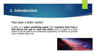
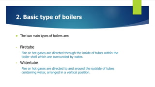
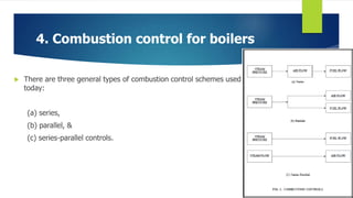
1. Boilers work by transferring heat from a fuel source like gas or coal to water to create steam, which can be used for various industrial processes.
2. There are two main types of boilers - firetube boilers where hot gases pass through tubes in the boiler shell, and watertube boilers where tubes containing water are surrounded by hot gases.
3. Boiler controls are needed to increase uptime, reduce emissions, maintain safety, and control costs. Controls regulate combustion, feedwater levels, steam pressure and temperature.
1. Basic Controls For Boilers
MENTOR : PROFESSOR VIDITA TILVA
BY:
AASHEESH TANDON (12BIC044)
PAXAJ SHUKLA (12BIC056)
2. 1. Introduction
How does a boiler works?
A boiler is a water containing vessel which transfers heat from a
fuel source (oil, gas or coal) into steam which is piped to a point
where it can be used to run production equipment, to sterilize, to provide
heat, to steam-clean, etc.
3. 1. Introduction
The energy given up by the steam is sufficient to convert it back
into the form of water. When 100% of the steam produced is
returned to be reused, the system is called a closed system.
4. 1. Introduction
Since some processes can contaminate the steam, so it is not
always desirable to feed the condensate back into the boiler. A
system that does not return the condensate is called an open
system.
5. 2. Basic type of boilers
The two main types of boilers are:
• Firetube
Fire or hot gases are directed through the inside of tubes within the
boiler shell which are surrounded by water.
• Watertube
Fire or hot gases are directed to and around the outside of tubes
containing water, arranged in a vertical position.
6. 3. Why need boiler controls?
1. Increase uptime and availability
2. Reduce flue gas emissions
3. Maintain boiler safety
4. Control operating costs
7. 4. Combustion control for boilers
A combustion control system is broken down into :
(a) fuel control
(b) combustion air control
8. 4. Combustion control for boilers
There are three general types of combustion control schemes used
today:
(a) series,
(b) parallel, &
(c) series-parallel controls.
9. 4(A). Hardware Used In Combustion Control
(a) ON/OFF controls
(b) Positioning systems
(c) Metering control system
10. 4.(B) Combustion Control Methods
Burner combustion control generally includes one or a combination of the
following methods:-
Excess air regulation
Oxygen trim
Burner modulation
Air/Fuel cross-limiting
Total heat control
11. 5. Feedwater Control For Boilers
Feedwater control is the regulation of water to the boiler drum.
Risks :
If the level is too high, may interfere with the internal operation of
internal devices in the boiler drum, such as - flooding of steam
purification equipment can occur.
If the level is too low, reduction in efficiency of the treatment and
recirculation function, undesired pressure build up, over heating of
boiler coils/tubes.
12. 5.(A) Components Affecting Drum Water Level
steam bubbles
Drum pressure
‘swell‘ : surge in water level as a result of the drum pressure decreasing
'shrink‘ : decrease in water level as result of drum pressure increasing
13. 5.(B) Single And Two Element Control
Systems
Single Element :
controls feed water flow based on drum level
Response is very slow
Two Element :
uses steam flow changes as a feed forward signal
flow and level transmitters are summed by a computing relay
response is faster
14. 5.(C) Three Element Control
Used when :
unstable feedwater system exists
if large unpredictable steam demands are frequent
17. 5.(C) Five And Seven Element Control
Five element control is better than Three Element control in terms of :
steam flow measurement is temperature compensated, &
drum level measurement is pressure compensated.
Seven Element control is better than Five Element control in terms of :
Transmitters for blow down flow
Transmitters for soot blower flow
18. 5. Feedwater Control for Boilers
Advantages :
1. Multiple element feedwater control can help:
i. Faster response of systems.
ii. More accurate control.
iii. Maximum system stability.
2. Metering control system maintains combustion efficiency over
wide load changes and over long period of time
3. Parallel combustion control can be used in any size of boilers
19. 5. Feedwater Control for Boilers
Disadvantages :
1. Boilers require quick responding controls.
2. Level of the water in the boiler must be kept above 50% of height.
20. 6. Other Control Functions
A. Furnace air and draft control
B. Steam temperature control
C. Steam pressure and load control
Increase uptime and availability
The primary objective of most boilers operation is maintaining the uptime and availability. It is essential to maintain and upgrade the boiler control systems to assure steam availability.
Modern controls are more reliable and can be readily adjusts to load swings caused by varying plant operations.
Reduce flue gas emissions
Failure to comply with the current emissions regulations can be as costly as loss of utilities. Government mandates are enforced by fines, threat of closure, or imprisonment will provide sufficient incentives for plants to comply with the regulations; thus, modernize controls are necessary.
Improved in combustion efficiency means reduction in waste disposal problems. And by accurately controlling the oxygen, fuel flow and stack temperature, you will see reductions in plant emissions.
Maintain boiler safety
Modernize control system will have tight integration with flame safety or burner management system to improve safety.
Accessing field data, diagnostics functions and alarms can be achieved by coupling modern electronic controls. Password security of the configuration software also assures no unintended changes can be done which can endanger your personnel and equipment.
Control operating costs
Reduction in fuel consumption
Reduction in engineering, installation and startup costs
Reduction maintenance costs associated with older
equipment
Reduction manpower with automatic responds
Provide a flexible control strategy to reduce process upsets
Readily data available for remote monitoring to determine process optimization, boiler efficiency and load allocations
A combustion control system is broken down into (a) fuel control and (b) combustion air control subsystems. The interrelationship between these two subsystems necessitate the use of fuel air ration controls.
The primary boiler fuels are coal, oil and gas. The control of gas and oil fuels requires simplest controls- i.e. a control valve in the fuel line.
The steam drum pressure is an indication of balance between the inflow and outflow of heat. Therefore by controlling the steam supply one can establish balance between the demand for steam (process load) and supply of water.
In series control, variations in steam header pressure (the master control signal) cause a change in combustion air flow which in turn results in a sequential change in fuel flow. This type of control is limited to small boilers having relatively constant steam load & burning fuel.
In parallel control, variation in steam pressure simultaneously adjusts both fuel & air flows. This method is common to any size boilers.
In series-parallel, variation in steam pressure set points are used to adjust the fuel. Flow to the above boiler since steam flow is directly related to heat release of the fuel and hence the air flow, the steam flow can be used as an index of the required combustion air.
The control hardware used to carry out the above schemes include, ON/OFF controls, positioning & metering systems.
(a) ON/OFF controls:
Are still used in many industries but are generally used in small water tube boilers. When the pressure drops to a present value, fuel & air are automatically fed into the boiler at predetermined rate until pressure has risen to its upper limit.
(b) Positioning systems:
Respond to changes in header pressure by simultaneously positioning the forced draft damper and fuel valve to a predetermined alignment. This is not used in liquid, gaseous fuel – fired boilers.
(c) Metering control system:
In this system control is regulated in accordance with the measured fuel and air flows. This maintains combustion efficiency over a wide load ranges & over long period of time.
Both metering & positioning control systems use steam header pressure as their primary measured variable & as a basis for firing rate demand. A master pressure controller responds to changes on header pressure & positions the dampers to control air flow and fuel valve to regulate fuel supply
Proper boiler operation requires that the level of water in the steam drum should be maintained within certain band. A decrease in this level may uncover boiler tubes, allowing them to become overheated. An increase in the level of water may interfere with the internal operation of internal devices in the boiler drum. It is important to maintain, that the water level in the boiler drum must be above 50% all the time.
Under boiling conditions, steam supporting field products such as bubbles exist
below the water/steam level interface. These bubbles have volume and therefore
displace water to create a misrepresentation of the true water level in the drum.
Another effect upon drum level is pressure in the drum. Because steam bubbles
compress under pressure (if the drum pressure changes due to load demands), the
steam bubbles expand or contract respective to these pressure changes.
A higher steam demand will cause the drum pressure to drop, and the steam bubbles to
expand to give the appearance of a water level higher than it truly is. This fictitious
higher water level causes the feedwater input to be shut down at a time when more
water is really required. A surge in water level as a result of the drum pressure
decreasing is called 'swell'.
Now suppose the steam flow goes down abruptly(output side). This will result in drum pressurization, causing the bubbles to shrink further. The apparent water level comes down (SHRINKING). Under this condition the boiler needs only lesser feedwater flow than earlier as the output steam flow is less. If the control system is in single element mode, ie. it is observing only drum level the feedwater valves will be opened further to meet the fall in drum level. A water level decrease due to drum pressure increase
is called 'shrink'.
For small boilers having relatively high storage volumes and slow changing loads, single element control system is used. It controls feed water flow based on drum level. Response is very slow because a change in feedwater flow takes a long time to show up the level change. As a result the steam drum causes water to increase and decrease in volume, resulting in false measurements.
The two element system overcome these inadequacies by using steam flow changes as a feed forward signal. This control is used in intermediate boilers as well as large boilers. Here the flow and level transmitters are summed by a computing relay and will be the set point for feedwater. Here the response is faster.
THREE ELEMENT CONTROL
Boilers that experiences wide and rapid load changes require three element control. Three element control is similar to two element system except that the water flow loop is closed rather than open.
Control action, the third element based on feedwater flow. The level and steam flow signals are summed and used as an index or set point to the feedwater flow. The feedwater flow measurement provides corrective action for variation in feedwater pressure.
How it works:
Figure shows the control scheme for three-element drum level control. To the left
of the dotted line, the instrumentation is the same as that for the two-element drum
level control, with one exception: the output of the feedwater flow computer now
becomes the set-point of the feedwater flow controller (FIC-2). Equipment required
to complete our three-element drum level control scheme includes an additional
flow device (FE-2) and differential pressure transmitter (FT-2).
The area to the left of the dotted line in figure 4 functions the same as that of a two element
drum level control. We can pick up the operation for this scheme where the
output signal of the feedwater flow computer (the combination of steam flow and
drum level) enters the feedwater controller (FIC-2).
This in effect becomes the set-point to this controller. Feedwater flow Is measured
by the transmitter (FT-2). The output signal of the feedwater flow transmitter is
linearized by the square root extractor, (FY-2). This signal is the process variable to
the feedwater controller and is compared to the output of the feedwater flow computer
(set-point). The feedwater flow controller produces the necessary corrective signal
to maintain feedwater flow at its set-point by the adjustment of the feedwater control
valve (FCV-1).
As in the two-element drum level control scheme, nearly all of the work necessary to
compensate for load change is done by the feed-forward system (i.e. a pound of
feedwater change is made for every pound of steam flow change). The drum level
portion of the control scheme is used only in a compensating role. Despite low-to-moderate
volume/ throughput ratio and a wide operating range, it is expected the
drum level will be maintained very close to set-point.
A. Furnace air and draft control
Most furnaces for boilers are designed to be operated at slightly below atmospheric pressure to
ensure furnace gases do not escape to the atmosphere. The control function is therefore to adjust the draft extraction rate of the ID fan system to ensure the negative pressure conditions are maintained at the furnace within a narrow band whilst correcting for disturbances caused mainly by
air flow changes required by the combustion systems.
B. Steam temperature control
Steam temperature is critically important to many applications for example:
• Steam turbines operate most efficiently at specifically designed temperatures and are also
liable to be damaged by rapid temperature changes arising in the steam supply.
• Chemical process plants require steam at fixed superheat temperatures for stable and
correct operation of their heat exchanger stages.
Steam temperature of saturated steam is determined by the pressure so for saturated steam supplies only the pressure control is needed. For all other applications superheated steam must have its temperature controlled. This becomes more difficult as the boiler firing rate is reduced when the distribution of heat transfer between evaporation duty and superheating duty swings usually in favour of evaporation. Therefore superheat control strategies have to be devised by the boiler
designers so that the fireside duty can be adjusted along with the water spray de-superheater
system.
C. Steam pressure and load control
Pressure control in a single boiler is achieved by adjusting the firing rate so that the steam generation rate matches the steam flow rate at the desired pressure. The downstream users will largely determine the steam flow extracted from the boiler so that the boiler will operate in load following mode if it is adjusted to maintain the pressure at the drum or alternatively at the load entry point such as the steam header or turbine throttle. The general arrangement is shown