Downloaded 100 times
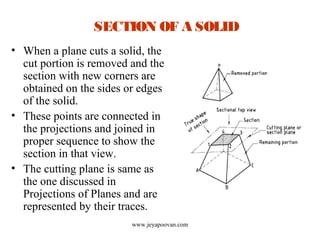
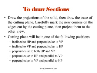
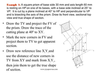
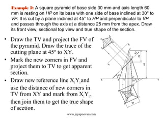
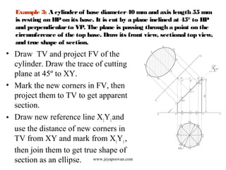
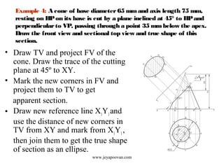
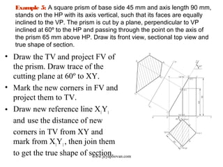


The document provides an overview of how to draw sections of various solids, including methods for determining new corners and projecting views after a cutting plane intersects the solid. It includes multiple examples with specific geometrical shapes such as prisms, pyramids, cylinders, and cones, demonstrating the application of cutting planes at different angles. Additionally, it offers tips for accurately marking and illustrating the sections along with references for further reading.


