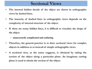
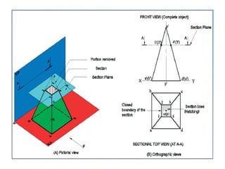
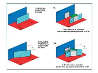
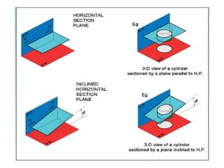
ENGINEERING GRAPHICS
TOPIC : SECTION OF SOLIDS
SUBJECT GUIDE :Dr. K. Raju
TEAM MATES :
NITHIN RAJ K
RAMKUMAR M R
SARAN S
SARAVANA KUMAR V
SRI HARIVARSHAN R
THULASIRAJ N S
Sectional Views
• The internal hidden details of the object are shown in orthographic
views by dashed lines.
• The intensity of dashed lines in orthographic views depends on the
complexity of internal structure of the object.
• If there are many hidden lines, it is difficult to visualize the shape of
the object
– unnecessarily complicated and confusing.
• Therefore, the general practice is to draw sectional views for complex
objects in addition to or instead of simple orthographic views.
• A sectional view, as the name suggests, is obtained by taking the
section of the object along a particular plane. An imaginary cutting
plane is used to obtain the section of the object.
Theory of Sectioning
• Whenever a section plane cuts a solid, it
intersects (and or coincides with) the edges
of the solids.
• The point at which the section plane
intersects an edge of the solid is called the
point of intersection (POI).
• In case of the solids having a curved
surface, viz., cylinder, cone and sphere,
POIs are located between the cutting plane
and the lateral lines.
True Shape of Sections
• A section will show its true shape when viewed in normal
direction.
• To find the true shape of a section, it must be projected on a
plane parallel to the section plane.
• For polyhedron, the true shape of the section depends on the
number of POIs. The shape of the section will be a polygon of
the sides equal to the number of POIs.
• The true shape of the section of a sphere is always a circle.
• The sections of prisms and pyramids are straight line segmented
curves.
• The sections of cylinders and cones will mostly have smooth
curves.
Types of Cutting Planes and Their Representation
• A cutting plane is represented by a cutting plane line
• The cutting plane line indicates the line view of the cutting plane.
• The two ends of the cutting plane line are made slightly thicker and provided with arrows.
• The direction of the arrow indicates the direction of viewing of the object.
• In the first-angle method
of projection, the direction
of the arrows is toward the
POP, i.e., toward XY.
• Types of section planes
• Vertical Section plane
• Horizontal Section
Plane
• Profile Section plane
• Auxiliary Section
plane
• Oblique Section plane
Hatching of the Sections
• The surface created by cutting the object by a section plane is called as section.
• The section is indicated by drawing the hatching lines (section lines) within
the sectioned area.
• The hatching lines are drawn at 45° to the principal outlines or the lines of
symmetry of the section
• The spacing between hatching lines should be uniform and in proportion to
the size of the section.
H or
HB
2H
• A squareprismof base side30mmandaxis length60mmis restingon HP on
one of its base with a base side inclinedat 25° to VP. It is cut by a plane inclined
at 40° to HP and perpendicularto VP and is bisectingthe axis of the prism.
Drawits frontview,sectionaltop view and true shapeof the section.
• A pentagonalpyramidof base side 25 mm and altitude 50 mm restson its base
on the HP withone of the base edge perpendicularto the VP. It is cut by a plane
inclinedat 45⁰ to the base.The cuttingplane meetsthe axis at 20 mm abovethe
base.Drawthe frontview,sectionaltop view and true shapeof the section.
A hexagonalprism of base side25mm and axis length55mmis restingon HP
on one of its bases withtwo of the verticalfaces perpendicularto VP. It is cut
by a plane inclinedat 50° to HP and perpendicularto VP and passingthrougha
pointat a distance12mmto the top base. Draw its front view,sectionaltop view
andtrue shapeof section.
A coneof base diameter120mmandheightof 135mmis restingon HP on its
base.It is cut by a sectionplaneinclined at 45° to the HP andpassingthrougha
pointon the axis andis 60mm belowthe vertex of the cone. Drawthe front
view,sectional top view and true shapeof section.Name the sectional
obtained and markits dimensionon it.
THANK YOU

ENGINEERING GRAPHICS ppt.ppt

  • 2.
    ENGINEERING GRAPHICS TOPIC :SECTION OF SOLIDS SUBJECT GUIDE :Dr. K. Raju TEAM MATES : NITHIN RAJ K RAMKUMAR M R SARAN S SARAVANA KUMAR V SRI HARIVARSHAN R THULASIRAJ N S
  • 4.
    Sectional Views • Theinternal hidden details of the object are shown in orthographic views by dashed lines. • The intensity of dashed lines in orthographic views depends on the complexity of internal structure of the object. • If there are many hidden lines, it is difficult to visualize the shape of the object – unnecessarily complicated and confusing. • Therefore, the general practice is to draw sectional views for complex objects in addition to or instead of simple orthographic views. • A sectional view, as the name suggests, is obtained by taking the section of the object along a particular plane. An imaginary cutting plane is used to obtain the section of the object.
  • 5.
    Theory of Sectioning •Whenever a section plane cuts a solid, it intersects (and or coincides with) the edges of the solids. • The point at which the section plane intersects an edge of the solid is called the point of intersection (POI). • In case of the solids having a curved surface, viz., cylinder, cone and sphere, POIs are located between the cutting plane and the lateral lines.
  • 6.
    True Shape ofSections • A section will show its true shape when viewed in normal direction. • To find the true shape of a section, it must be projected on a plane parallel to the section plane. • For polyhedron, the true shape of the section depends on the number of POIs. The shape of the section will be a polygon of the sides equal to the number of POIs. • The true shape of the section of a sphere is always a circle. • The sections of prisms and pyramids are straight line segmented curves. • The sections of cylinders and cones will mostly have smooth curves.
  • 7.
    Types of CuttingPlanes and Their Representation • A cutting plane is represented by a cutting plane line • The cutting plane line indicates the line view of the cutting plane. • The two ends of the cutting plane line are made slightly thicker and provided with arrows. • The direction of the arrow indicates the direction of viewing of the object. • In the first-angle method of projection, the direction of the arrows is toward the POP, i.e., toward XY. • Types of section planes • Vertical Section plane • Horizontal Section Plane • Profile Section plane • Auxiliary Section plane • Oblique Section plane
  • 8.
    Hatching of theSections • The surface created by cutting the object by a section plane is called as section. • The section is indicated by drawing the hatching lines (section lines) within the sectioned area. • The hatching lines are drawn at 45° to the principal outlines or the lines of symmetry of the section • The spacing between hatching lines should be uniform and in proportion to the size of the section. H or HB 2H
  • 12.
    • A squareprismofbase side30mmandaxis length60mmis restingon HP on one of its base with a base side inclinedat 25° to VP. It is cut by a plane inclined at 40° to HP and perpendicularto VP and is bisectingthe axis of the prism. Drawits frontview,sectionaltop view and true shapeof the section.
  • 13.
    • A pentagonalpyramidofbase side 25 mm and altitude 50 mm restson its base on the HP withone of the base edge perpendicularto the VP. It is cut by a plane inclinedat 45⁰ to the base.The cuttingplane meetsthe axis at 20 mm abovethe base.Drawthe frontview,sectionaltop view and true shapeof the section.
  • 14.
    A hexagonalprism ofbase side25mm and axis length55mmis restingon HP on one of its bases withtwo of the verticalfaces perpendicularto VP. It is cut by a plane inclinedat 50° to HP and perpendicularto VP and passingthrougha pointat a distance12mmto the top base. Draw its front view,sectionaltop view andtrue shapeof section.
  • 15.
    A coneof basediameter120mmandheightof 135mmis restingon HP on its base.It is cut by a sectionplaneinclined at 45° to the HP andpassingthrougha pointon the axis andis 60mm belowthe vertex of the cone. Drawthe front view,sectional top view and true shapeof section.Name the sectional obtained and markits dimensionon it.
  • 16.