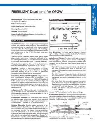
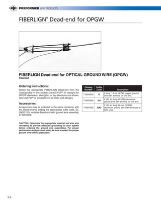
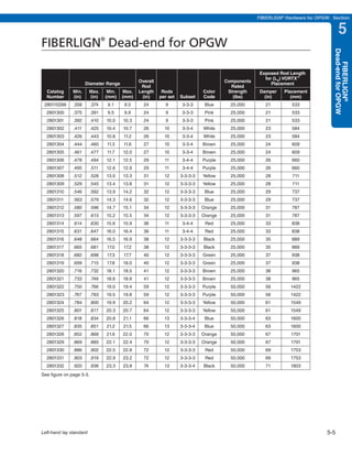
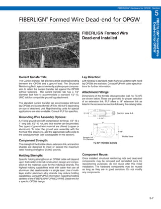
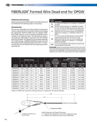
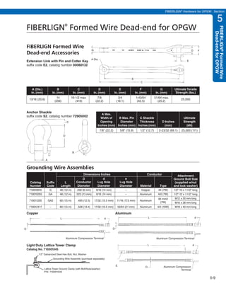
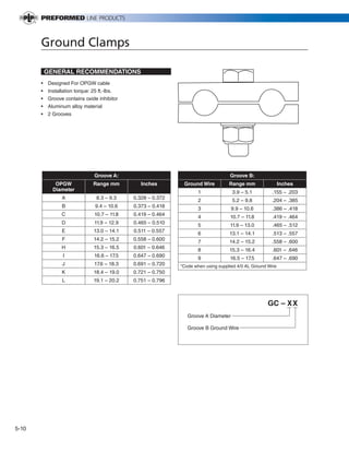
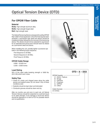
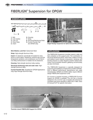
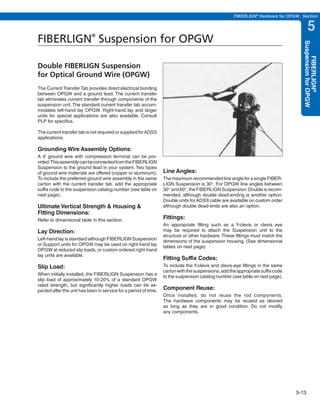
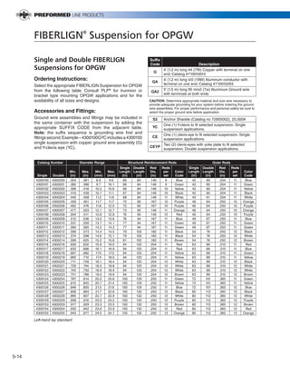
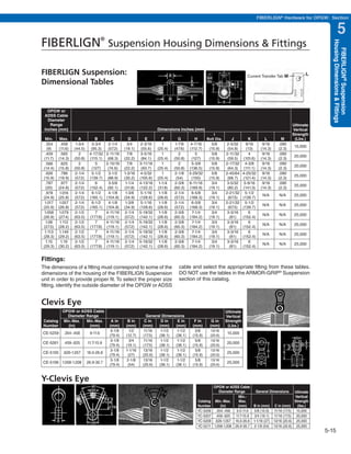
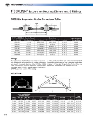
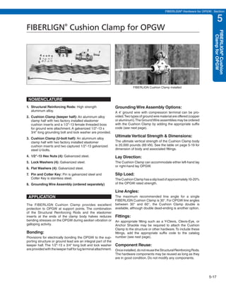
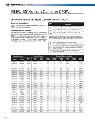
This document section describes PLP's FIBERLIGN hardware products for OPGW (Optical Ground Wire), including dead-ends, formed wire dead-ends, ground clamps, optical tension devices, suspensions, cushion clamps, and repair rods. It provides details on the components, applications, and ordering instructions for the FIBERLIGN Dead-end for OPGW, which utilizes retaining rods, wedges, a housing and U-bolt to distribute loading over the OPGW while minimizing compression stresses on the optical elements. Dimensions, strengths, and acceptable fittings are specified.

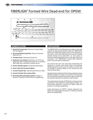


![RF Circuit Design - [Ch1-2] Transmission Line Theory](https://cdn.slidesharecdn.com/ss_thumbnails/ch1-2-150613064349-lva1-app6892-thumbnail.jpg?width=640&height=640&fit=bounds)


