Download to read offline


![Physical – Layer 1 Protocol Data Unit
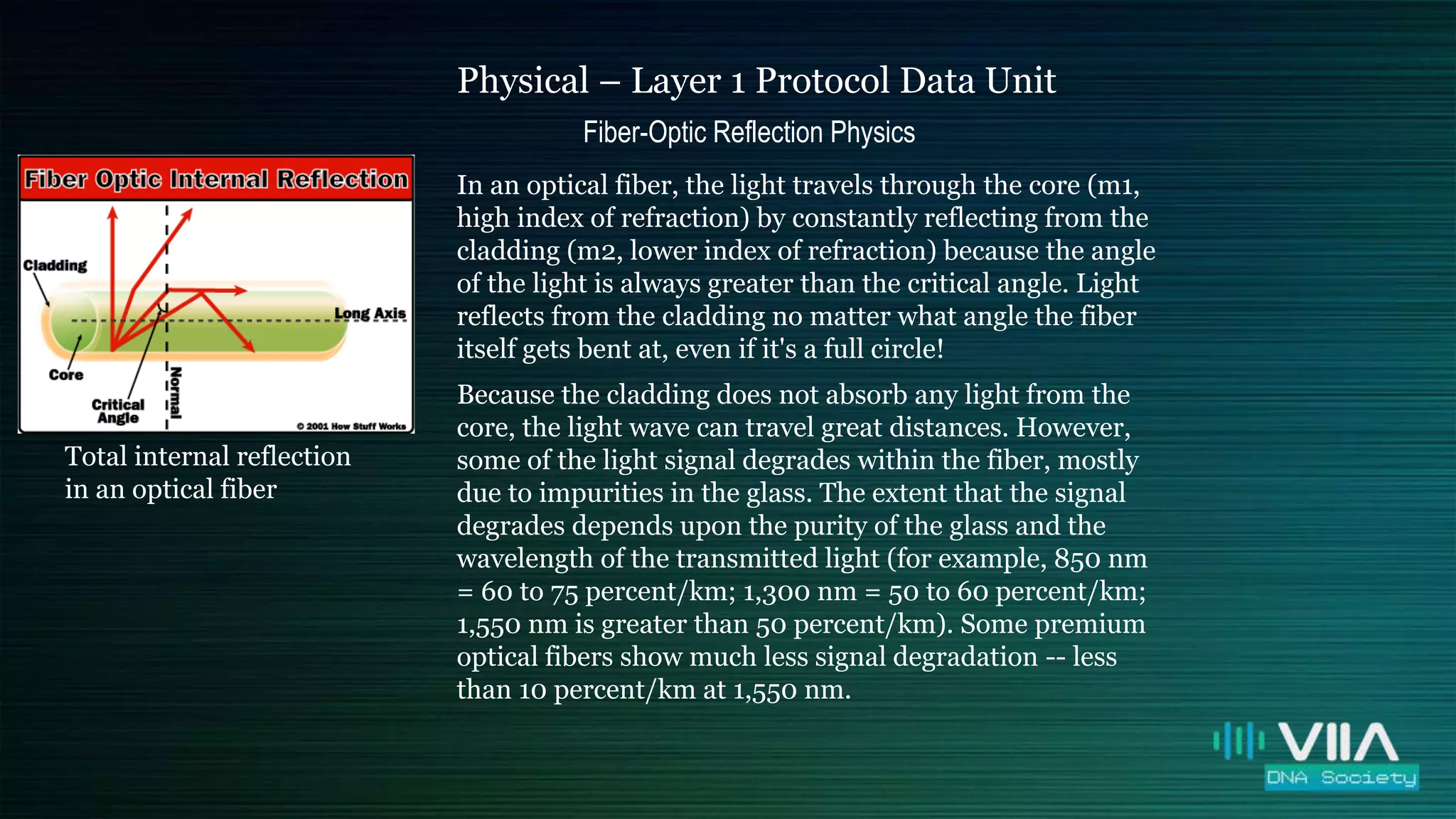
Fiber-Optic Reflection Physics
Total internal reflection
in an optical fiber
When light passes from a medium with one index of
refraction (m1) to another medium with a lower index of
refraction (m2), it bends or refracts away from an
imaginary line perpendicular to the surface (normal
line). As the angle of the beam through m1 becomes
greater with respect to the normal line, the refracted light
through m2 bends further away from the line.
At one particular angle (critical angle), the refracted
light will not go into m2, but instead will travel along the
surface between the two media (sine [critical angle] =
n2/n1 where n1 and n2 are the indices of refraction [n1 is
greater than n2]). If the beam through m1 is greater than
the critical angle, then the refracted beam will be reflected
entirely back into m1 (total internal reflection), even
though m2 may be transparent!
Fiber-optic critical angle = (90 degrees - physics critical
angle).](https://image.slidesharecdn.com/osi-howfiberopticswork-200612140701/75/OSI-Model-How-Fiber-Optics-Works-19-2048.jpg)


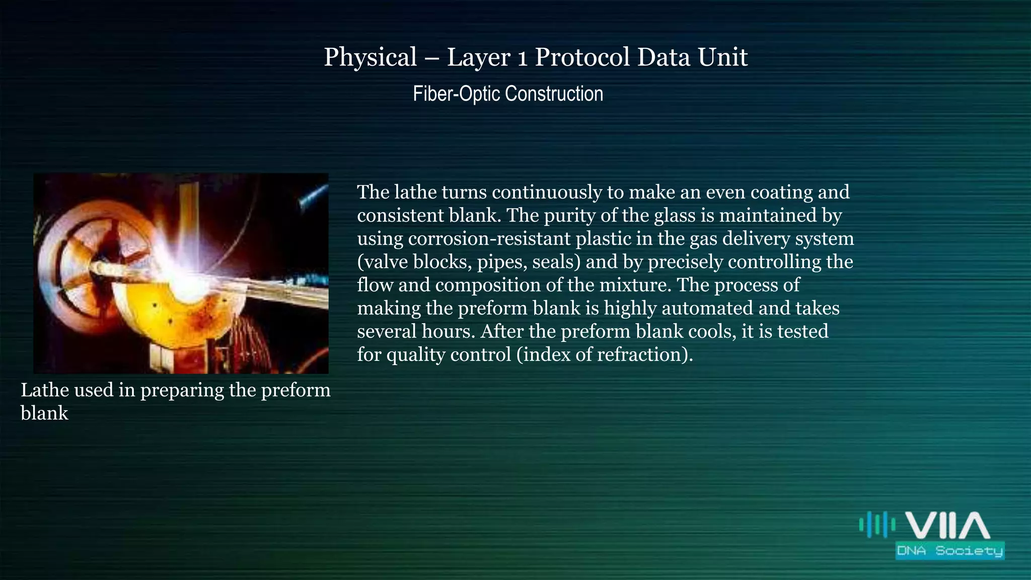
The document provides an overview of fiber optics, detailing their structure, function, and advantages in telecommunications. It explains how light is transmitted through optical fibers via total internal reflection and describes the construction process including preform making and fiber drawing. The material highlights various types of fibers, their uses, and the significance of maintaining high glass purity to minimize signal degradation.