This document discusses reliability engineering and how it fits within the system engineering lifecycle. It provides an overview of reliability engineering processes and tools used to optimize risk for projects. Some key points made include:
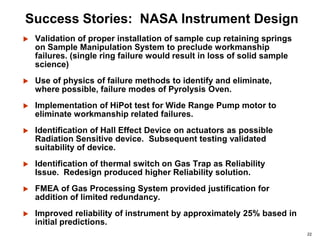
- Reliability engineering exists to help design out failure modes and reduce operational risk through a partnership with system engineering teams.
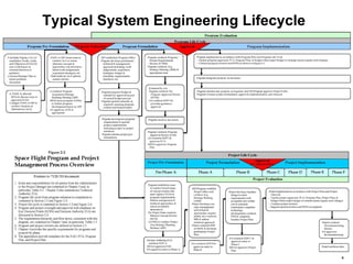
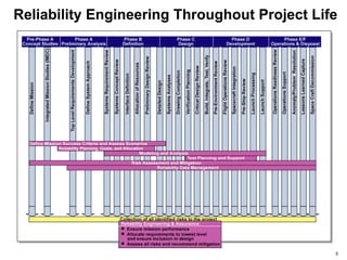
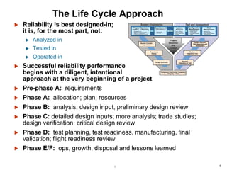
- Reliability processes are applied throughout the project lifecycle from requirements development through operations and disposal. Tools include FMEA, FTA, simulation, testing and data analysis.
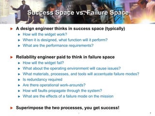
- The goal is for engineers to think about both success space (how things work) and failure space (how things can fail) to design out failures and ensure mission success.