The document discusses systems engineering challenges and opportunities, including:
1) Growing mission complexity is exceeding our ability to manage risk, and system designs emerge from pieces rather than sound architectures, resulting in brittle systems.
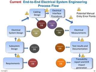
2) Technical and programmatic sides of projects are poorly coupled, hampering decision making and increasing risk.
3) Too much focus on process comes at the expense of design quality, driving up costs and risk.
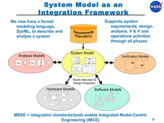
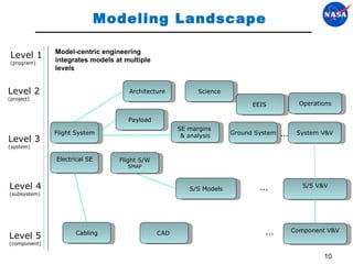
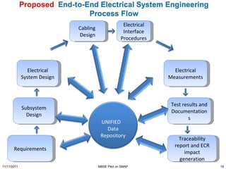
The document proposes addressing these with model-based systems engineering, architecture frameworks, and integrating technical and programmatic considerations through architecture.