Download as PDF, PPTX
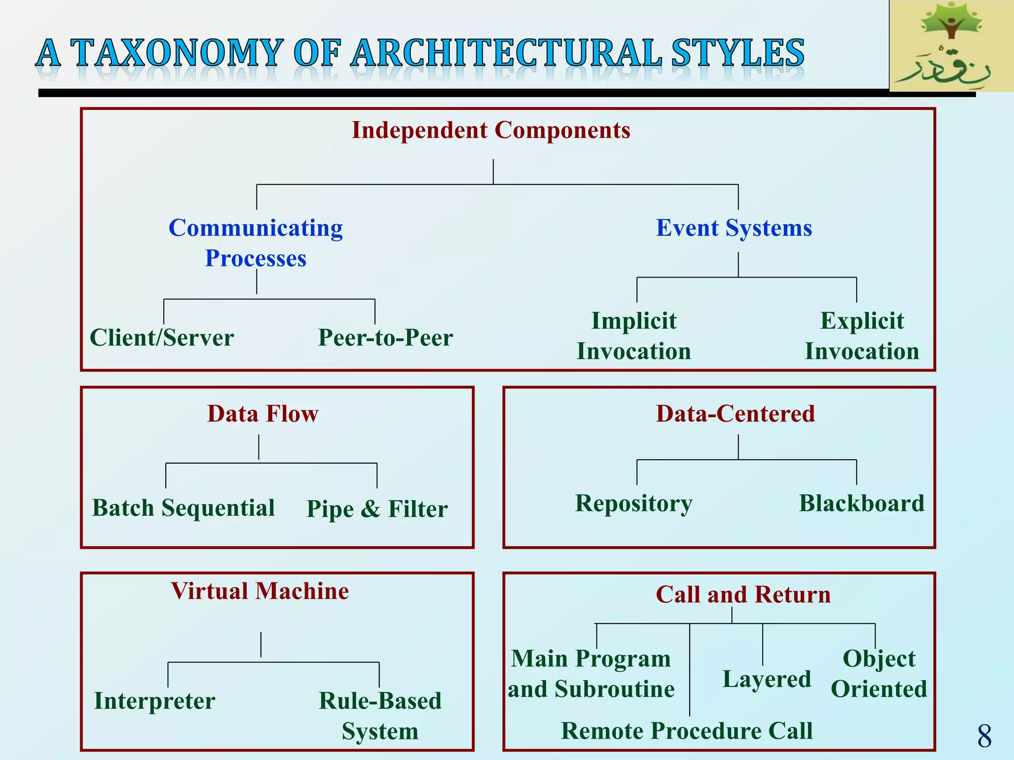
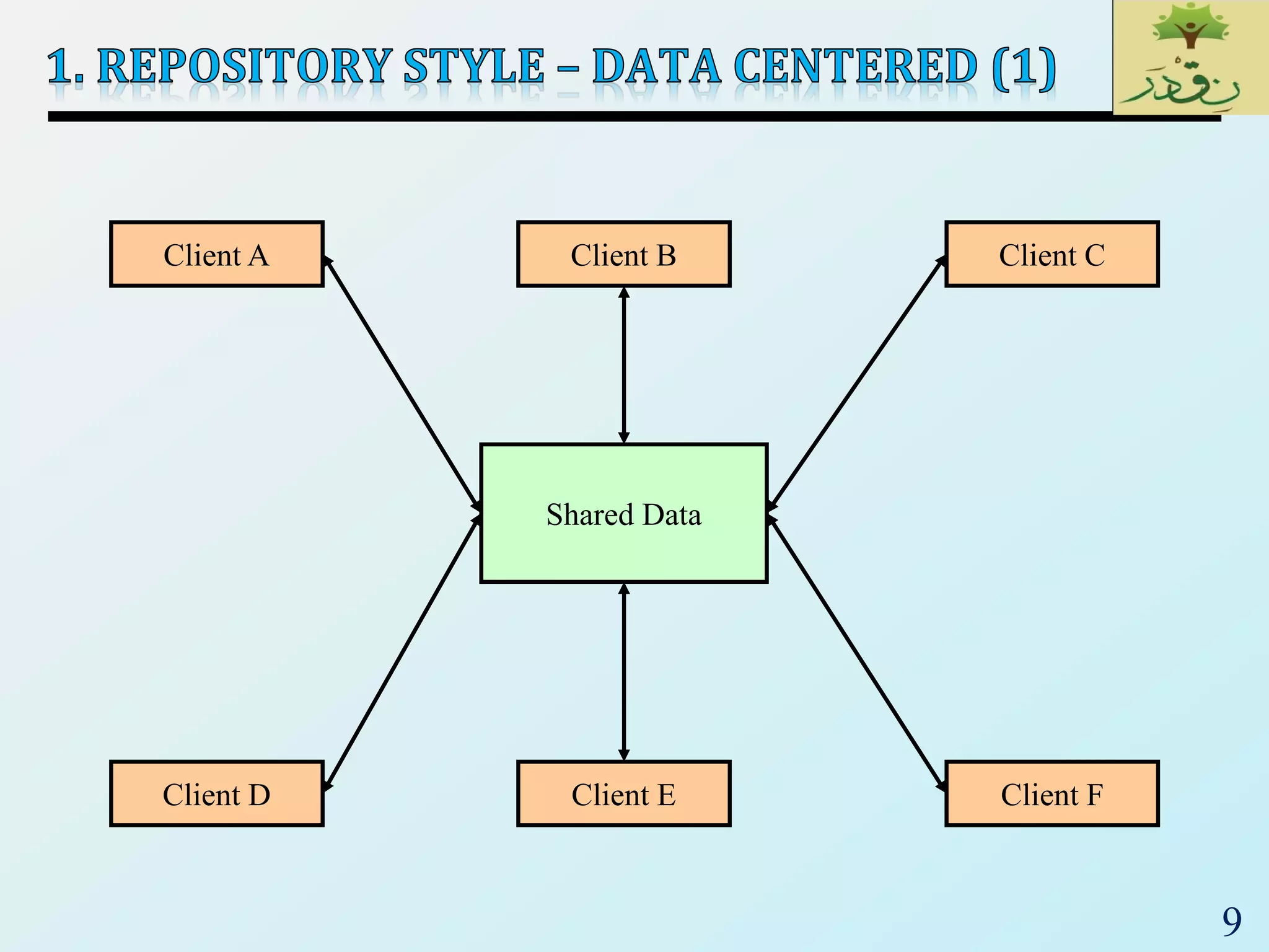
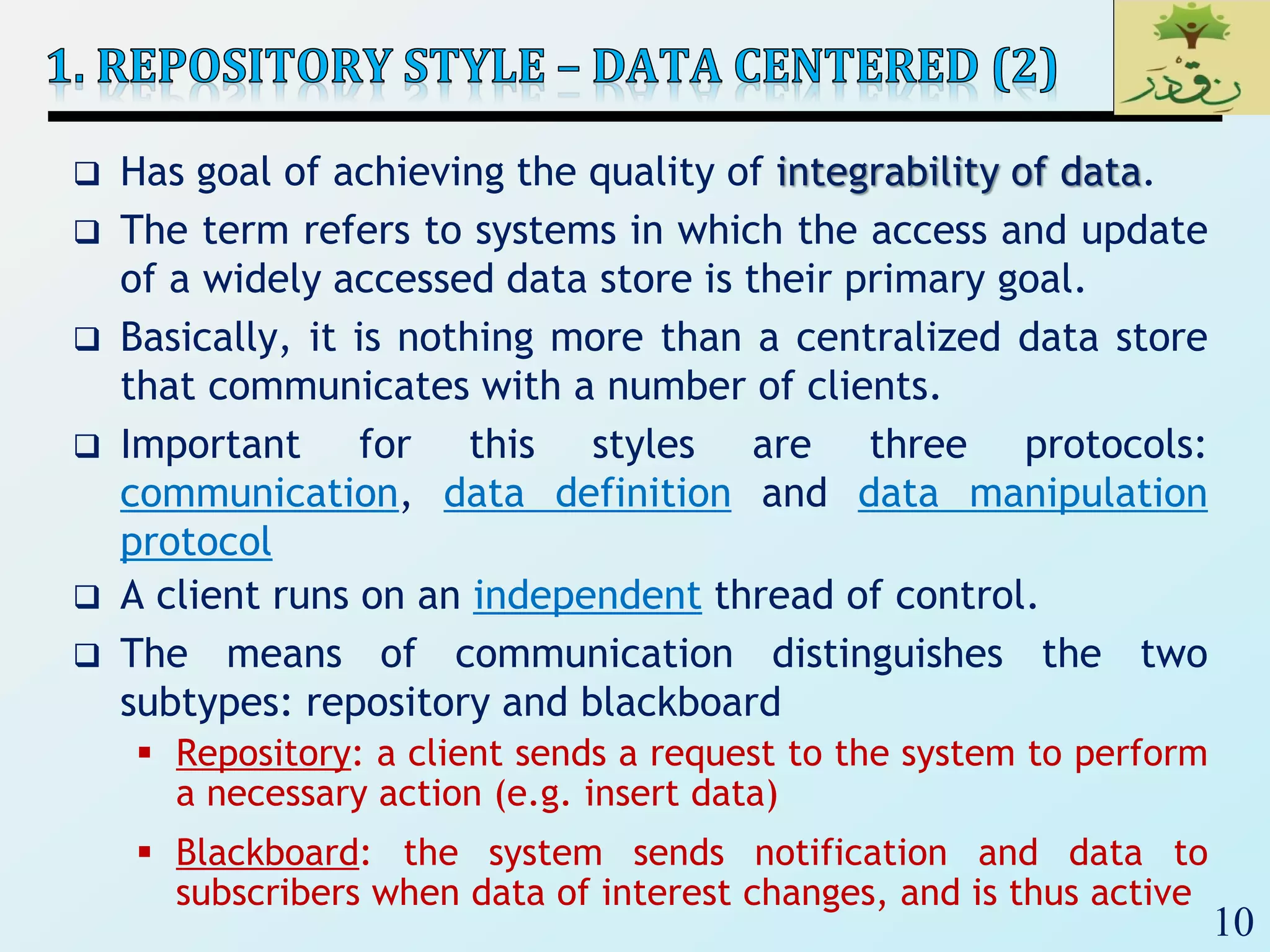
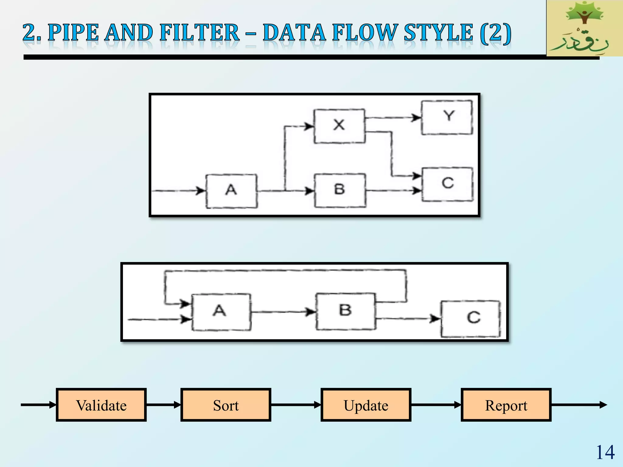
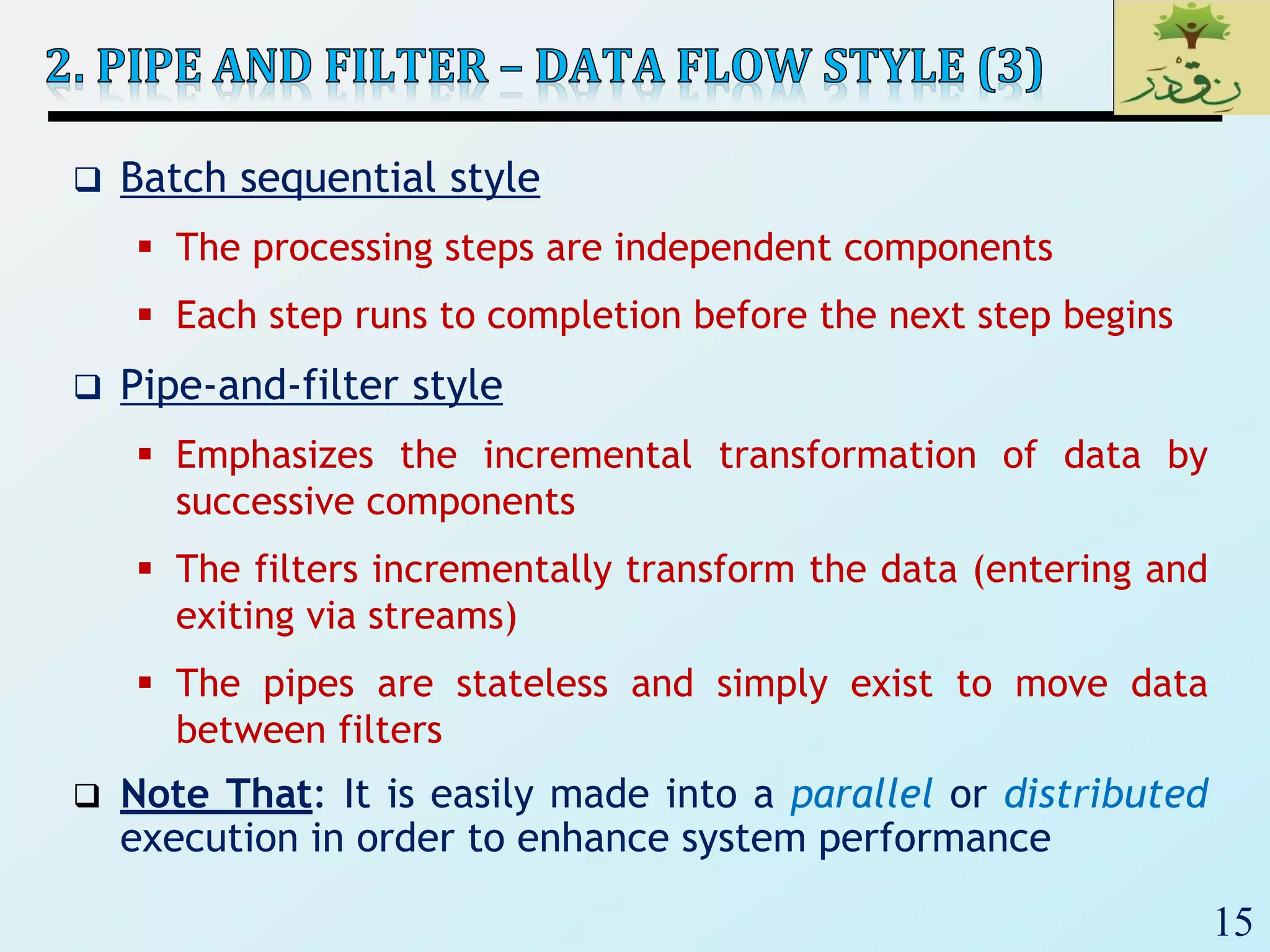
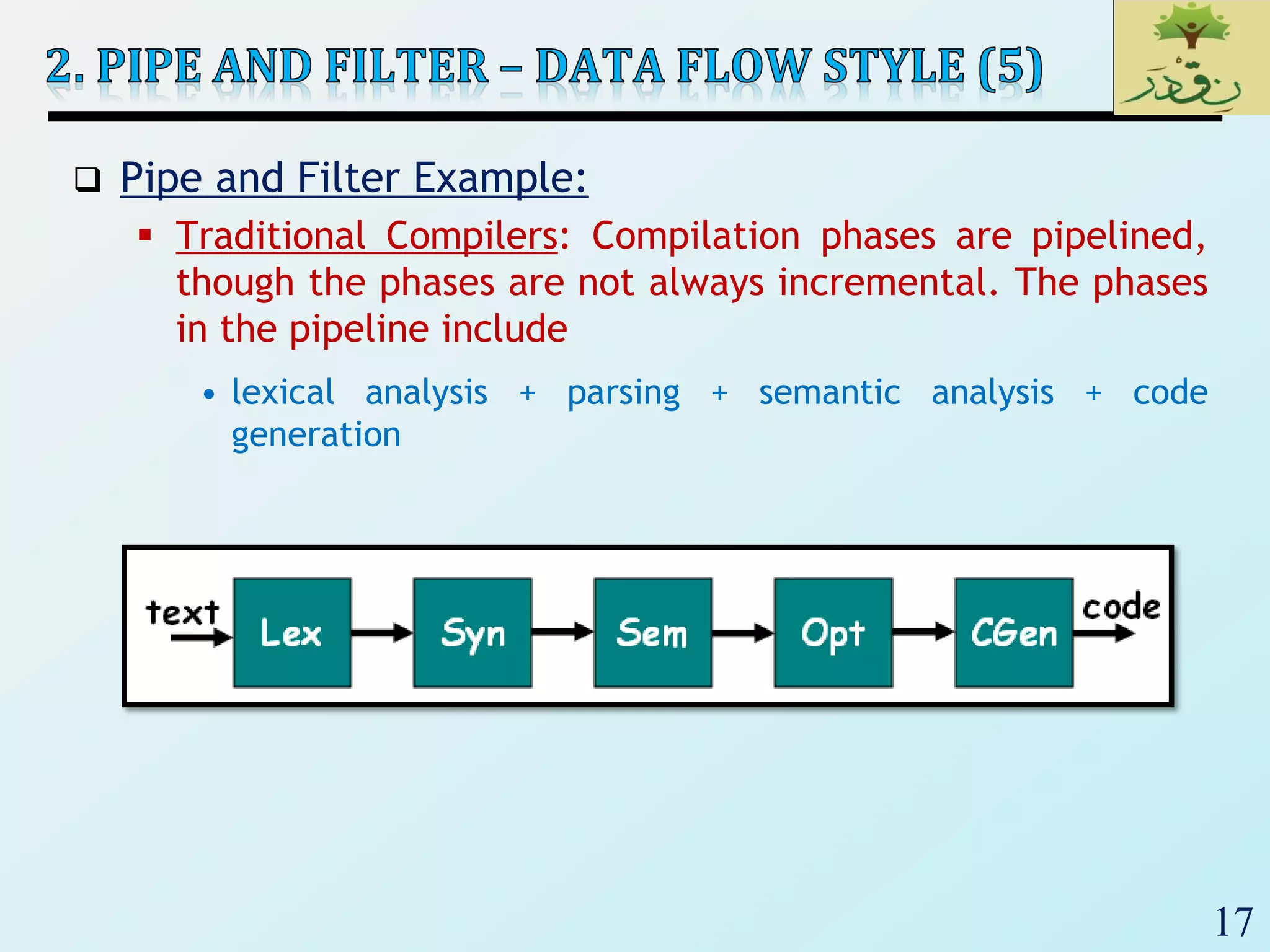
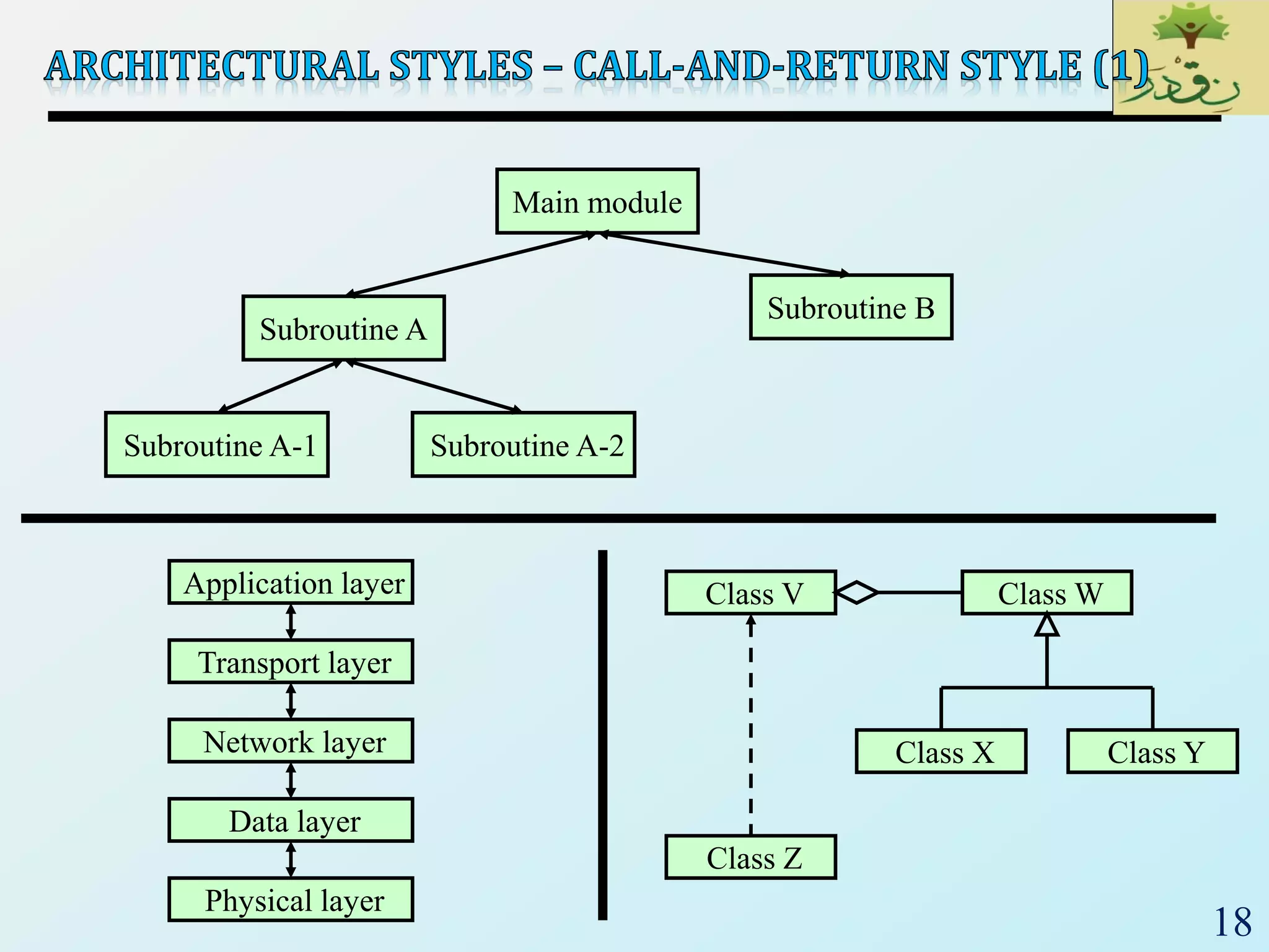
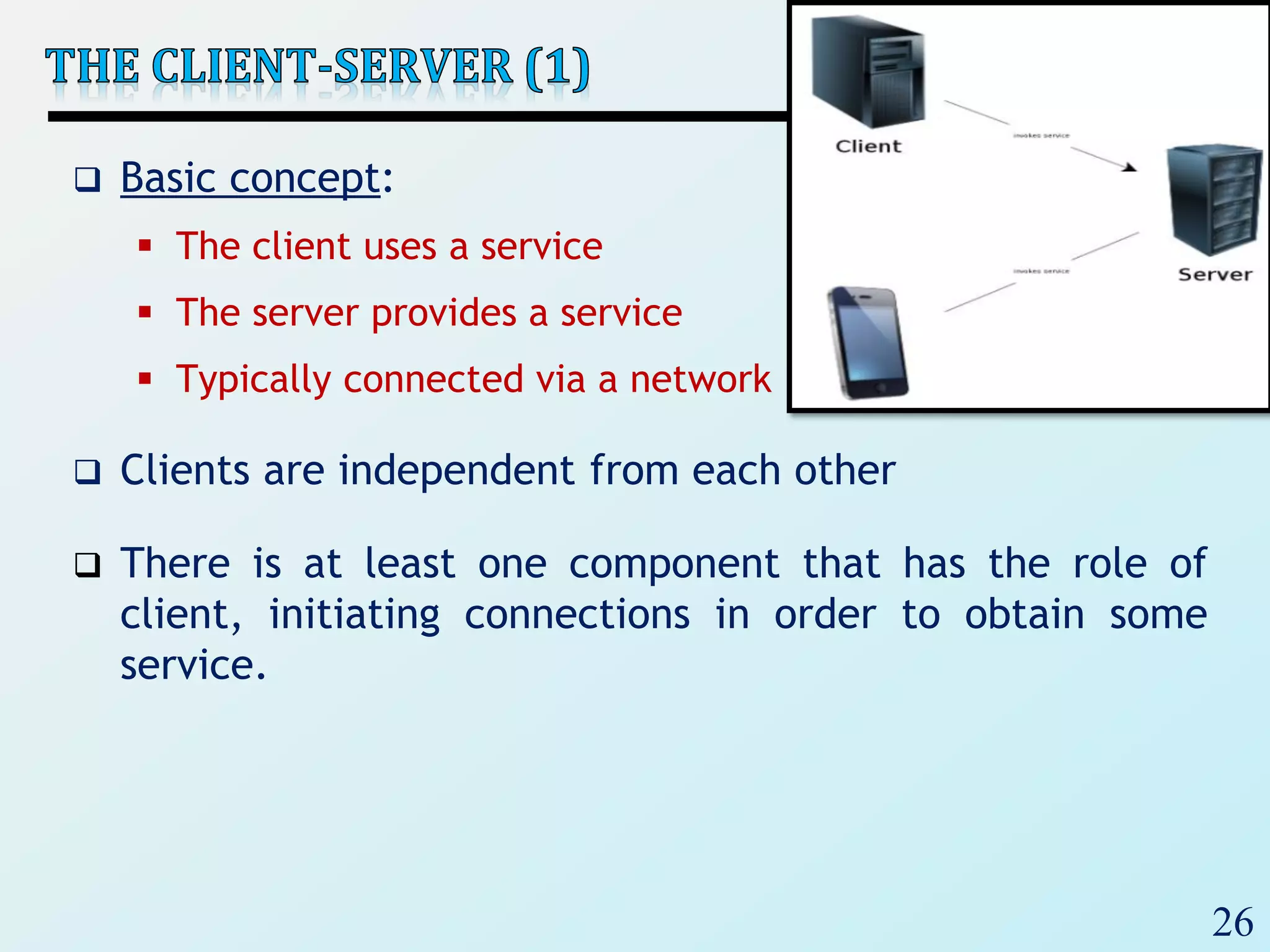
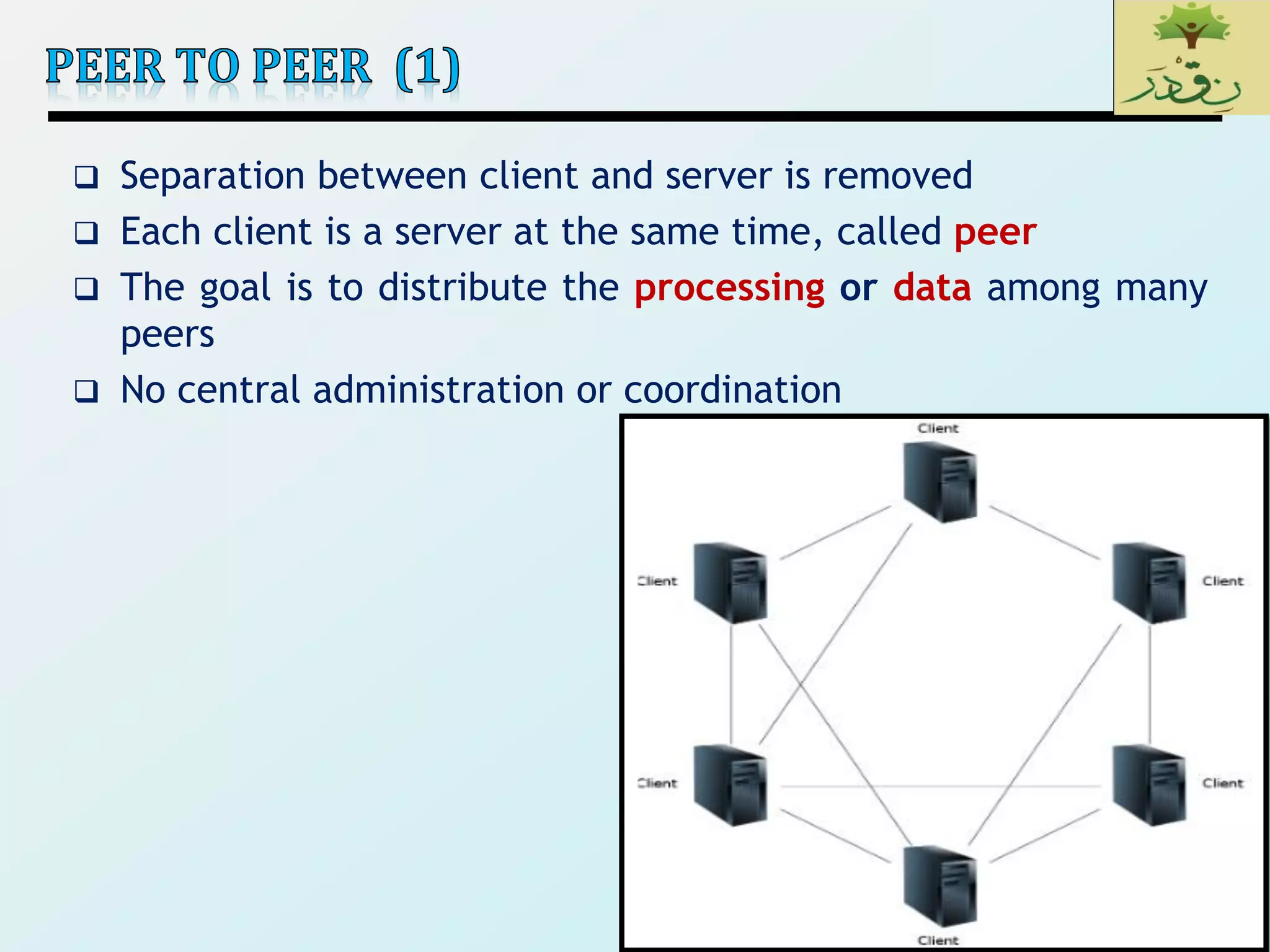


The document discusses various software architectural styles. It provides descriptions and examples of different styles including: 1) Data-centered architectures which focus on integrating data access and use a centralized data store. Examples given are repository and blackboard styles. 2) Pipe-and-filter architectures which view systems as data transformations through a series of components. Both batch sequential and incremental pipe-and-filter styles are covered. 3) Client-server architectures which separate systems into independent clients that request services from servers. Peer-to-peer is also discussed as a related style.