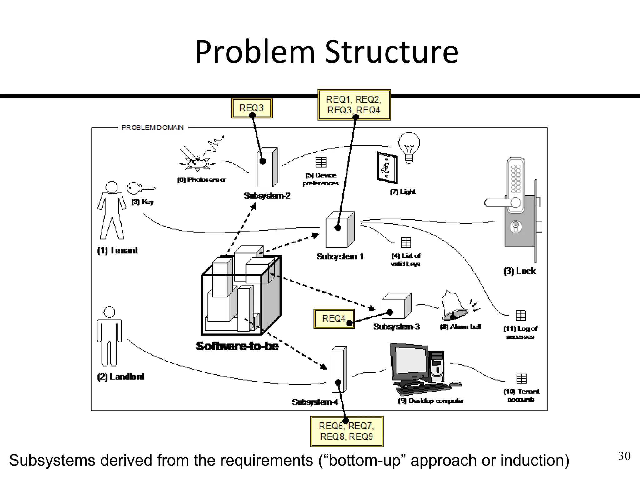
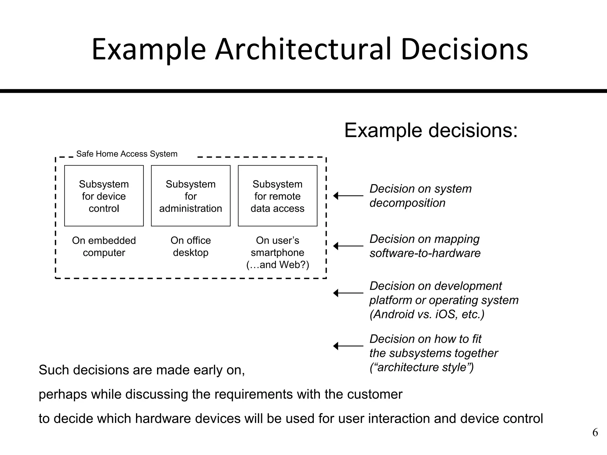
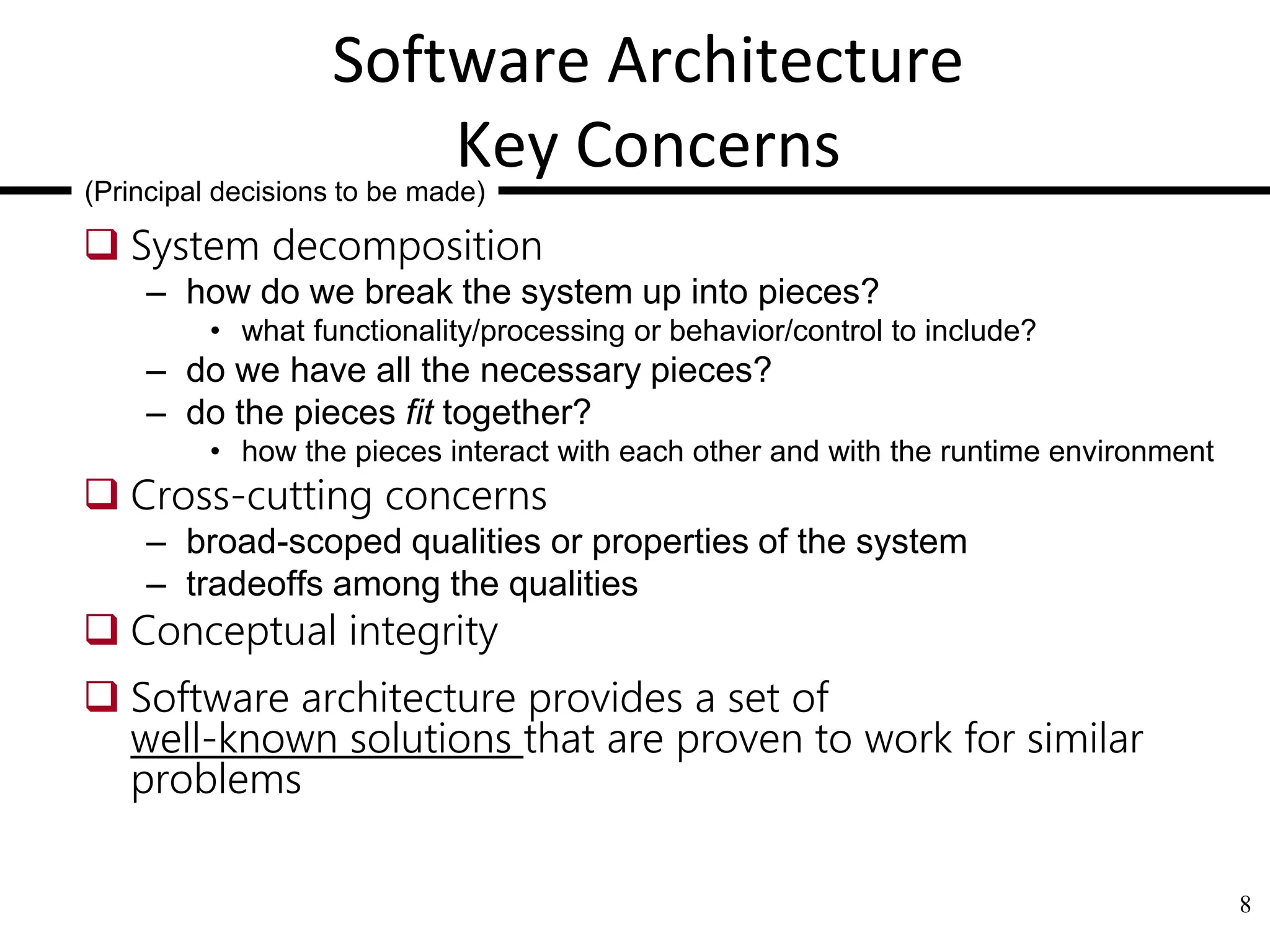
3. Hierarchical Organization of Software
Software is not one long list of program statements but it has structure
The above is a taxonomy of structural parts (abstraction hierarchy), but
not representation of relationships between the parts and does not
specify the function of each part
3
System or product
Subsystems/Modules
Packages
Classes/Objects
Methods
highest abstraction level
lowest level
Product line (or product family)
Source code
But first, why do we want to decompose systems?
The hierarchy shows a taxonomy of the system parts, but not the procedure for decomposing
the system into parts — how do we do it?
4. 4
Why We Want To
Decompose Systems
Tackle complexity by “divide-and-conquer”
See if some parts already exist & can be reused
Focus on creative parts and avoid “reinventing the
wheel”
Support flexibility and future evolution by
decoupling unrelated parts, so each can evolve
separately (“separation of concerns”)
Create sustainable strategic advantage
5. Software Architecture Definition
Software Architecture =
a set of high-level decisions that determine the structure of the
solution
(parts of system-to-be and their relationships)
– Principal decisions made throughout the development and evolution
of a software system
– made early and affect large parts of the system (“design philosophy”)
— such decisions are hard to modify later
Decisions to use well-known solutions that are proven to work for
similar problems
Software Architecture is not a phase of development
– Does not refer to a specific product of a particular phase of the
development process (labeled “high-level design” or “product design”)
5
6. 6
Example Architectural Decisions
Subsystem
for device
control
Subsystem
for
administration
Subsystem
for remote
data access
On embedded
computer
On office
desktop
On user’s
smartphone
(…and Web?)
Safe Home Access System
Decision on mapping
software-to-hardware
Decision on system
decomposition
Such decisions are made early on,
perhaps while discussing the requirements with the customer
to decide which hardware devices will be used for user interaction and device control
Example decisions:
Decision on development
platform or operating system
(Android vs. iOS, etc.)
Decision on how to fit
the subsystems together
(“architecture style”)
7. 7
Architectural Decisions
—A matter of scope
Product/system A scope Product B scope
Product line scope
Subsystem scope
product or system
architecture decisions
product line
architecture decisions
• Given the current level of system scope, a decision
is “architectural” if it can be made only by
considering the present scope
– I.e. could not be made from a more narrowly-scoped, local perspective
– Architectural decisions should focus on high impact, high priority areas
that are in strong alignment with the business strategy
systemic impact
local impact
Class scope
8. 8
Software Architecture
Key Concerns
System decomposition
– how do we break the system up into pieces?
• what functionality/processing or behavior/control to include?
– do we have all the necessary pieces?
– do the pieces fit together?
• how the pieces interact with each other and with the runtime environment
Cross-cutting concerns
– broad-scoped qualities or properties of the system
– tradeoffs among the qualities
Conceptual integrity
Software architecture provides a set of
well-known solutions that are proven to work for similar
problems
(Principal decisions to be made)
9. 9
Architectural Decisions Often Involve
Compromise
The “best” design for a component considered in
isolation may not be chosen when components
considered together or
within a broader context
– Depends on what criteria are used to decide the “goodness”
of a design
– E.g., car components may be “best” for racing cars or “best”
for luxury cars, but will not be best together
Additional considerations include business priorities,
available resources, core competences, target customers,
competitors’ moves, technology trends, existing investments,
backward compatibility, …
10. 10
Module/Subsystem Views
Module Decomposition View
– Top-down refinement (e.g., simple “block diagram”)
Dependency View
– How parts relate to one another
Layered View
– Special case of dependency view
Class View
– “domain model” in OOA and “class diagram” in OOD
11. 11
Component and Connector Views
Process View
– Defined sequence of activities?
System represented as a series of communicating processes
Concurrency View
Shared Data View
– …
Client/Server View
– E.g., in Web browsing
12. A component has its behavior defined in terms of
provided interfaces and required interfaces
(potentially exposed via ports)
UML Notation for Software Components
12
«component»
Consumer
«component»
Provider
Required
Interface
Provided
Interface
“Provider” component
provides («realize»)
functionality through
Provided Interface.
“Consumer”
component
accesses («use»)
functionality through
Required Interface.
Method call
from consumer
component
(“output port”)
Called method
implemented
by provider
component
(“inputport”)
dependency
13. 13
How to Fit Subsystems Together:
Some Well-Known Architecture Styles
World Wide Web architecture style:
REST (Representational State Transfer)
UNIX shell script architecture style:
Pipe-and-Filter
Client/Server
Central Repository (database)
Layered (or Multi-Tiered)
Peer-to-Peer
Microservices
Development platform (e.g.,
Web vs. mobile app, etc.)
may dictate the architecture
style or vice versa…
15. 15
Architecture Styles –
Constituent Parts
1. Components
– Processing elements that “do the work”
2. Connectors
– Enable communication among components
• Broadcast Bus, Middleware-enabled, implicit (events), explicit (procedure
calls, ORBs, explicit communications bus) …
3. Interfaces
– Connection points on components and connectors
• define where data may flow in and out of the components/connectors
4. Configurations
– Arrangements of components and connectors that form an
architecture
16. Connectors: HTTP Protocol
POST method requests the server to create a new resource
GET method requests the server to read a resource
PUT method requests the server to update a resource
DELETE method requests the server to delete a resource
16
Time
Client Server
GET /index.html HTTP 1.1
Host: caip.rutgers.edu
Accept: image/gif, image/x-xbitmap, image/
jpeg, image pjpeg, */*
Accept-Language: en-us
Accept-Encoding: gzip, deflate
User-Agent: Mozilla/4.0 (compatible, MSIE
5.01; Windows NT)
Connection: Keep-Alive
HTTP/1.1 200 OK
Date: Thu, 23 Feb 2006 21:03:56 GMT
Server: Apache/2.0.48 (Unix) DAV/2 PHP/4.3.9
Last-Modified: Thu, 18 Nov 2004 16:40:02 GMT
ETag: "1689-10a0-aab5c80"
Accept-Ranges: bytes
Content-Length: 4256
Content-Type: text/html; charset=ISO-8859-1
Connection: close
<HTML>
<HEAD>
<TITLE>CAIP Center-Rutgers University</TITLE>
</HEAD>
Client Request Message
Server Response Message
17. Shared Database Connector
— Data Model for Restaurant
17
employee assigned dining table food order menu item
exactly one zero or one
zero or more
one or more
Entity-relationship diagram of the data model:
Crow’s foot diagram of the same data model:
employee (identifier, name, role, salary, …)
assigned (date, working shift)
dining table (identifier, capacity, status, seated customers)
food order (time, item, quantity, total price, status)
menu item (identifier, price, ingredients, availability)
payment (time, date, amount, confirmation number)
- ordered
- prepared
- ready
- served
relationship set
entity set
attribute
employee assigned dining table food order menu item
role
emp-id
name
date shift
capacity
status
customers
salary
date
time
quantity
status
mi-id
price
availability
ingredients
tbl-id
19. Architecture Style: Client/Server
A client is a triggering process; a server is a reactive process. Clients make
requests that trigger reactions from servers.
A server component, offering a set of services, listens for requests upon those
services. A server waits for requests to be made and then reacts to them.
A client component, desiring that a service be performed, sends a request at
times of its choosing to the server via a connector.
The server either rejects or performs the request and sends a response back to
the client
19
Client Server
Packing a request
for network transport
Unpacking the request
for server call
Packing the response
for network transport
Unpacking the response
for client use
Network connection
packets packets
1: 4: 2: 3:
components
connector
Connector
Client Server
User
20. Architecture Style: Layered
A layered system is organized hierarchically, each layer providing
services to the layer above it and using services of the layer below
it
Layered systems reduce coupling across multiple layers by hiding
the inner layers from all except the adjacent outer layer, thus
improving evolvability and reusability
20
a.k.a. Tiered Software Architecture
User Interface Layer User Interaction
Algorithms &
Data Processing
Storage, Networking,
& Device Drivers
ApplicationLogic Layer
(Business Policies)
Technical Services Layer
(Mechanisms & Utilities)
21. REST: Hypermedia as the Engine of
Application State (HATEOAS)
21
… text link<S3> text
image link<S4> text
text text image
link<S5> text …
State S1
State S2
State S3
State S4
State SN
State S5
URI(S4)
Hypermedia representation
(webpage) of State S2
State transition
HTTP GET URI(S5)
… text text text
text link<S3>
text …
State transition
HTTP GET URI(S3)
Hypermedia representation
(webpage) ofState S5
REST Client REST Server
HTTP Request
HTTP Response
URI(S2)
URI(S5)
URI(S3)
URI(S2)
URI(S3)
URI(S3)
URI(S5)
REST: Representational state transfer
Conceptual model: hypermedia as the engine of application state (HATEOAS)
22. Hypermedia as the Engine of Application
State
22
user
State #1 representation:
hypermedia ofsearch page
State transition
(HTTP GET keywords)
… text text text
text link text …
State transition
(HTTP GET retailer)
State #2 representation:
hypermedia ofsearch results
… text text link
image text text …
State #3 representation:
hypermedia ofproduct info
Product Finding
Server resource:
hypermedia of
initial search page
Product Selecting
Server resource:
productcatalog
Product Reviewing
Server resource:
database record for
productinformation
Product Purchasing
Server resource:
database record of
billing/shipping options
Application state #1
Application state #2
Appl. state #3
Application state #4
… text text image
link text text …
State transition
(HTTP POST productto cart)
… text link text
text text text …
State #4 representation:
hypermedia of product info
Web application:
A network of Web resources (a virtual state-machine), where the user by following the links
requests the transfer of next resource (“state”).
23. REST physical model
23
Client
User interface
Stateless server:
no memoryabout
pastrequests by
a given client
Session state
at client:
memoryabout
pastand current
requests
Request(e.g.,
HTTP) contains
all the information
describing the
desired resource
or service,
identified by URI Intermediary
Response caching
Server
Data storage
Web resources
Web resource:
Identified using URI;
Arbitrary representation
internal to the server
Response:
representation of
resource in standard
text format(HTML,
XML, JSON, …);
includes hyperlinks to
other Web resources
24. RESTful Resource Naming
24
create employees { name, role, salary }
John Doe waiter 1000
CRUD operation
(verb)
Resource name Input arguments
(noun)
(a)
(b)
POST /employees/ HTTP 1.1
Host: www.restaurant.com
...
Content-Type: application/x-www-form-urlencoded
Content-Length: 45
name=John%20Doe&role=waiter&salary=1000
Client Request Message
HTTP method
(verb)
Resource URI
(noun)
(a) Conceptual representation of creating a new employee record
(b) HTTP request message carrying the content of the HTML form that was used
to enter the employee data
25. REST, a resource-based architecture style
Client/server style that supports caching and replicated repositories
Uniform interface between components based on HTTP methods and URI-named resources,
which is efficient for coarse-grain hypertext/hypermedia data transfer
Server dynamically communicates to clients the application logic in hypertext or in code-on-
demand
Hypertext does not specify the operations allowed on a resource; it just contains embedded
hyperlinks that determine all possible transitions from the current to the next application state
For every media type, the server has defined a default processing model; standard formats for
message payload representation (HTML, XML, JSON, JPEG, …) ensure interoperability between
different clients and servers
Stateless sessions—each request must carry all the information needed for its processing
Statelessness may cause network inefficiency, so requires caching to avoid redundant responses
A RESTful API looks like hypertext
• Every addressable unit of information carries an address or identifier, either explicitly (e.g., link and id attributes) or implicitly
(e.g., derived from the media type definition and representation structure)
– Every media type defines a default processing model
– Hypertext doesn’t specify the operations allowed on a resource;
it specifies which operation to use for each potential state transition
25
26. RESTful API Design versus
JSON-RPC APIs over HTTP
26
RESTful APIs JSON-RPC APIs over HTTP
URIs for resource addresses URIs for object addresses
Focus on navigable resources (nouns) Focus on data-processing procedures (verbs)
HATEOAS, application logic runs on
the server
Application logic runs on the client; the server
manages the data using CRUD and application-
specific RPCs
HTTP methods for resource CRUD
actions, plus media-specific server-
side controllers activated by the media
type
HTTP methods for service actions, plus
application-specific server-side procedures
explicitly addressed with the verb as part of the
request message URI
Message body can be any standard
media format, as negotiated by clients
and servers
Message body encoded as JSON objects
Code-on-demand
No code in response messages—only JSON
objects
Caching and replication of resource
content
Caching and replication not relevant for
procedures
28. 28
Architecture Style:
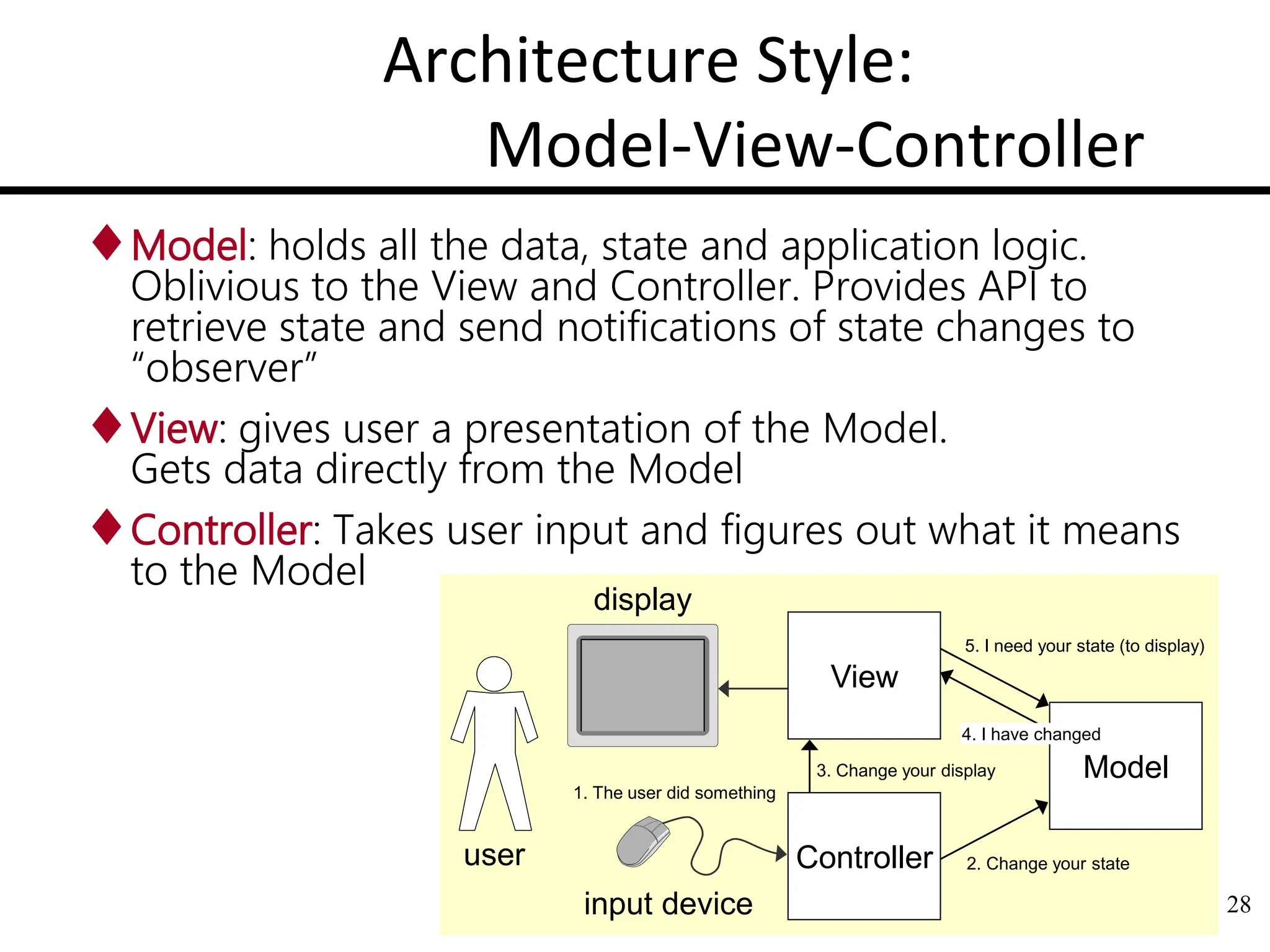
Model-View-Controller
Model: holds all the data, state and application logic.
Oblivious to the View and Controller. Provides API to
retrieve state and send notifications of state changes to
“observer”
View: gives user a presentation of the Model.
Gets data directly from the Model
Controller: Takes user input and figures out what it means
to the Model
user
input device
display
View
Controller
Model
5. I need your state (to display)
1. The user did something
2. Change your state
3. Change your display
4. I have changed
31. 31
Typical Software Eng. Problems
1. User works with computer system
(problem domain is “virtual”, not physical)
2. Computer system controls the (physical) problem domain
(user not involved)
3. Computer system intermediates between
the user and the problem domain
User
User System Problem domain
User Repository
User System Problem domain
IN doc
1.a) System transforms input document to output document
1.b) User edits information stored in a repository
3.a) System observes the problem domain and displays information
3.b) System controls the problem domain as commanded by the user
REQ-2: Allow repository editing, where
“repository” is a collection of data
REQ-3: Autonomously control
a physical object/device
REQ-5: Monitor and display
information about an object
REQ-4: Interactively control
a physical object/device
System Problem domain
REQ-1: Map input data to output
data as said by given rules
User System Problem domain
System
OUT doc
User System
32. 5-dimensional Problem Space
The five elementary problem types
represent the coordinate system of
the problem space
The “axis” projections represent the
degree to which the whole problem
contains a subproblem of this type
Each subproblem can be analyzed
independently and eventually
recombined into the whole
problem
The structure of the solution should
be selected to fit the problem
structure
32
Autonomous
control
(“Required
behavior”)
Simple
editing
(“Simple
workpieces”)
Software
problem
to solve
33. 33
Controlling
subsystem
Controlled
subsystem
3.b) Commanded behavior:
Operator
Monitoring
subsystem
Monitored
subsystem
3.a) Information display:
Display
Software (i.e., Solution) Structure
2. Required behavior:
Controlling
subsystem
Controlled
subsystem
Feeding
subsystem
Transformation
subsystem
Receiving
subsystem
1.a) Transformation:
Data
editor
Data repository
1.b) Simple editing:
User
SYSTEM
SYSTEM
SYSTEM
SYSTEM
SYSTEM
REQ-1: Map input data to output data as said by given rules
REQ-2: Allow repository editing, where “repository” is a collection of data
REQ-3: Automatically control a physical object/device
REQ-5: Monitor and display information about an object
REQ-4: Interactively control a physical object/device