Downloaded 34 times
![Process Specification (PSPEC eg)
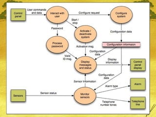
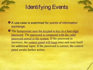
Process password (at control panel).
Process password receives a four-digit password
from the interact with user function. The password is
first compared to the master password stored within
the system. If the master password matches, [valid id
message = true] is passed to the message and status
display function. If the password does not match the
four digits are compared to the table of secondary
passwords(may assigned to guests etc). If the
password matches an entry within the table, [valid id
message = true] is passed to the message and status
display function. If there is no match, [valid id
message = false] is passed to the message and
status display function.](https://image.slidesharecdn.com/softwareengg-131201023118-phpapp01/85/Software-engg-pressman_ch-8-20-320.jpg)

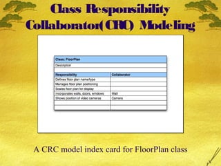
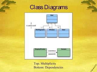
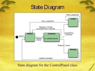
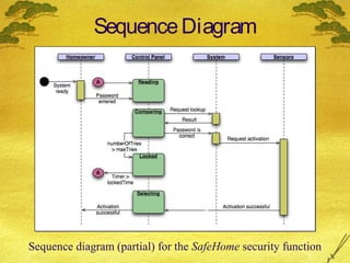

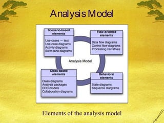
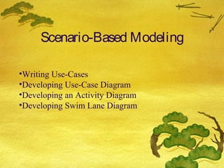
This document discusses various modeling techniques used during the analysis phase of software engineering. It covers scenario-based modeling including use cases, activity diagrams, and swimlane diagrams. It also discusses flow-oriented modeling using data flow diagrams and grammars. Additionally, it discusses class-based modeling including identifying analysis classes, class diagrams, and the class-responsibility-collaborator technique. Finally, it discusses behavioral modeling including identifying events and creating state and sequence diagrams.