Download to read offline
![1K.Mohana Krishna Int. Journal of Engineering Research and Applications www.ijera.com
ISSN : 2248-9622, Vol. 5, Issue 4, ( Part -7) April 2015, pp.99-103
www.ijera.com 99 | P a g e
Fault Tolerant Parallel Filters Based On Bch Codes
K.Mohana Krishna1
, Mrs.A.Maria Jossy2
1
Student, M-TECH(VLSI Design) SRM UniversityChennai, India
2
Assistant Professor (O.G), Department of Electronics and Communication SRM University Chennai, India
Abstract
Digital filters are used in signal processing and communication systems. In some cases, the reliability of those
systems is critical, and fault tolerant filter implementations are needed. Over the years, many techniques that
exploit the filters’ structure and properties to achieve fault tolerance have been proposed. As technology scales,
it enables more complex systems that incorporate many filters. In those complex systems, it is common that
some of the filters operate in parallel, for example, by applying the same filter to different input signals.
Recently, a simple technique that exploits the presence of parallel filters to achieve multiple fault tolerance has
been presented. In this brief, that idea is generalized to show that parallel filters can be protected using Bose–
Chaudhuri–Hocquenghem codes (BCH) in which each filter is the equivalent of a bit in a traditional ECC. This
new scheme allows more efficient protection when the number of parallel filters is large.
Keywords: Bose-Chaudhuri-Hocquenghem(BCH), filters, fault tolerance
I. INTRODUCTION
Finite impulse response (FIR) digital filters are
common components in many digital signal
processing (DSP) systems . Throughout the years,
with the increasingly development in very large scale
integration (VLSI) technology, the real time
realization of FIR filter with less hardware
requirement and less latency has become more and
more important. Because the complexity of
implementation grows with the length of filter,
several algorithms have been made to develop
effective architectures for realization of FIR filters in
application specific integrated circuits (ASIC) and
field programmable gate arrays (FPGA) platforms
and one of them is error robust design. The main
portion of error tolerant -based FIR computation is
parity blocks that stores the pre-computed values and
can be read out easily, which makes FIR computation
well suited for FPGA realization, because the
memory is the basic components of FPGA.
Moreover, this technology represents a number
of attractive features such as simplicity, regularity
and modularity of architecture. Also, the error
detection technique can be designed to meet various
speed requirements, for example, it can be designed
for high-speed implementation where all bits of one
word are processed per clock, it can also be designed
for medium-speed implementation where several bits
of one word (not all bits) are processed per clock. In
recent years, fault tolerant-based FIR filter has
gained substantial popularity as a primary DSP
operation and are rapidly replacing classic analog
filters.
II. PARALLEL FILTERS
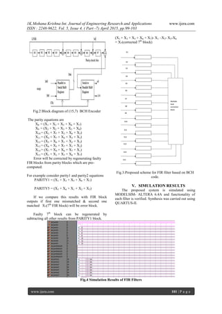
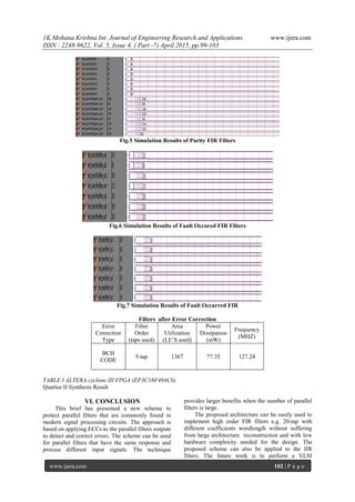
In any FIR filter convolution is carried out by
y[n] = ∑ x[n − l] · h [l].
Where x[n] is the input signal, y[n] is the output,
and h[l] is the impulse response of the filter [7].
When the response h[l] is nonzero, only for a finite
number of samples, the filter is known as a FIR filter,
otherwise the filter is an infinite impulse response
(IIR) filter. There are several structures to implement
both FIR and IIR filters.
The data and parity check bits are stored and can
be recovered later even if there is an error in one of
the bits. This is done by recomputing the parity
check bits and comparing the results with the values
stored.
Figure1. fault tolerant FIR filter based on hamming
code
RESEARCH ARTICLE OPEN ACCESS](https://image.slidesharecdn.com/p5040799103-150501062502-conversion-gate01/85/Fault-Tolerant-Parallel-Filters-Based-On-Bch-Codes-1-320.jpg)
![1K.Mohana Krishna Int. Journal of Engineering Research and Applications www.ijera.com
ISSN : 2248-9622, Vol. 5, Issue 4, ( Part -7) April 2015, pp.99-103
www.ijera.com 99 | P a g e
Fault Tolerant Parallel Filters Based On Bch Codes
K.Mohana Krishna1
, Mrs.A.Maria Jossy2
1
Student, M-TECH(VLSI Design) SRM UniversityChennai, India
2
Assistant Professor (O.G), Department of Electronics and Communication SRM University Chennai, India
Abstract
Digital filters are used in signal processing and communication systems. In some cases, the reliability of those
systems is critical, and fault tolerant filter implementations are needed. Over the years, many techniques that
exploit the filters’ structure and properties to achieve fault tolerance have been proposed. As technology scales,
it enables more complex systems that incorporate many filters. In those complex systems, it is common that
some of the filters operate in parallel, for example, by applying the same filter to different input signals.
Recently, a simple technique that exploits the presence of parallel filters to achieve multiple fault tolerance has
been presented. In this brief, that idea is generalized to show that parallel filters can be protected using Bose–
Chaudhuri–Hocquenghem codes (BCH) in which each filter is the equivalent of a bit in a traditional ECC. This
new scheme allows more efficient protection when the number of parallel filters is large.
Keywords: Bose-Chaudhuri-Hocquenghem(BCH), filters, fault tolerance
I. INTRODUCTION
Finite impulse response (FIR) digital filters are
common components in many digital signal
processing (DSP) systems . Throughout the years,
with the increasingly development in very large scale
integration (VLSI) technology, the real time
realization of FIR filter with less hardware
requirement and less latency has become more and
more important. Because the complexity of
implementation grows with the length of filter,
several algorithms have been made to develop
effective architectures for realization of FIR filters in
application specific integrated circuits (ASIC) and
field programmable gate arrays (FPGA) platforms
and one of them is error robust design. The main
portion of error tolerant -based FIR computation is
parity blocks that stores the pre-computed values and
can be read out easily, which makes FIR computation
well suited for FPGA realization, because the
memory is the basic components of FPGA.
Moreover, this technology represents a number
of attractive features such as simplicity, regularity
and modularity of architecture. Also, the error
detection technique can be designed to meet various
speed requirements, for example, it can be designed
for high-speed implementation where all bits of one
word are processed per clock, it can also be designed
for medium-speed implementation where several bits
of one word (not all bits) are processed per clock. In
recent years, fault tolerant-based FIR filter has
gained substantial popularity as a primary DSP
operation and are rapidly replacing classic analog
filters.
II. PARALLEL FILTERS
In any FIR filter convolution is carried out by
y[n] = ∑ x[n − l] · h [l].
Where x[n] is the input signal, y[n] is the output,
and h[l] is the impulse response of the filter [7].
When the response h[l] is nonzero, only for a finite
number of samples, the filter is known as a FIR filter,
otherwise the filter is an infinite impulse response
(IIR) filter. There are several structures to implement
both FIR and IIR filters.
The data and parity check bits are stored and can
be recovered later even if there is an error in one of
the bits. This is done by recomputing the parity
check bits and comparing the results with the values
stored.
Figure1. fault tolerant FIR filter based on hamming
code
RESEARCH ARTICLE OPEN ACCESS](https://image.slidesharecdn.com/p5040799103-150501062502-conversion-gate01/75/Fault-Tolerant-Parallel-Filters-Based-On-Bch-Codes-1-2048.jpg)
![1K.Mohana Krishna Int. Journal of Engineering Research and Applications www.ijera.com
ISSN : 2248-9622, Vol. 5, Issue 4, ( Part -7) April 2015, pp.99-103
www.ijera.com 100 | P a g e
III. ERROR CORRECTION
Convolution codes are important because they
are commonly used both as channel coding technique
and as building blocks in other techniques as turbo
codes and LDPC codes. Turbo code is a forward
error correction code class and was the first practical
code to perform near channel capacity.
For each of n input bits to the encoder the output
is m bits where m ≥ n ((m,n) code) and the code ratio
is R = n/m, generally a lower code ratio R (more
redundancy) increases the error correction/detection
possibility A parity check matrix H with dimensions
(m − n) × m is then used to check if the incoming
codeword is valid
Using the well known (7,4) Hamming code as an
example we have the generator matrix
And the parity check matrix
A tanner graph can be generated using the parity
check matrix H of a code, where the nodes to the left
correspond to codeword bits and the right nodes
corresponds to check equations. E.g. the first row in
the (7,4) Hamming code corresponds to check node,
the check equation is
z1[n] = y1[n] + y2[n] + y3[n]
z2[n] = y1[n] + y2[n] + y4[n]
z3[n] = y1[n] + y3[n] + y4[n].
For example, an error on filter y1 will cause
errors on the checks of z1, z2, and z3. Similarly, errors
on the other filters will cause errors on a different
group of zi. Therefore, as with the traditional ECCs,
the error can be located and corrected.
For the filters, correction is achieved by
reconstructing the erroneous outputs using the rest of
the data and check outputs. For example, when an
error on y1 is detected, it can be corrected by making
yc1 [n] = z1 [n] − y2 [n] − y3 [n]
IV. PROPOSED SCHEME
The block codes are implemented as (n, k) codes
where n indicates the codeword and the k defines the
original information bits. Therefore, the number of
redundant bits need to be added in to the original
message bits are given as (n – k). The block codes
are fixed channel codes. The BCH codes and the
Reed Solomon codes are the subset of the block
codes. Choose n, k, t values
n- Block length
k- Message bit
t- Error correcting code
n = 15
k = 7
t = 2
The block length of the BCH code, constructed
over GF (2m
) is given by n = 2m – 1
. BCH codes are
cyclic codes, and the degree r of the generator
polynomial of a (n, k) is given by (n-k). So, the
information bits length of the BCH codes is given by
k = 2m
– 1- r. In a Block codes the Codeword is a
combination of an information bits and parity bits.
The information bits are those bits which carries
the message while parity bits provide security and
ensure that the codeword has a correct structure
required for the block codes. Encoder generates the
parity bits as well as concatenates them to the
information bits. For k – information bits and r-
parity bits the generated codeword n will be the sum
of information bits and parity bits, given as n= k + r.
In this work we carried out (15, 7) BCH encoder
based FIR parity generation and its equivalent
decoder is designed.
The generator polynomial of the code is
specified in terms of its roots over the Galois field
GF (2m
). Let α be a primitive element in GF (2m
).The
generator polynomial g(x) of the code is the lowest
degree polynomial over GF (2). Let mi(x) be the
minimum polynomials of αi then generator
polynomial G(x) can be computed
G(x) = LCM [m1(x), m3(x), …., m2t(x)]
In this work n=15, k=7 and t=2 is considered.
Hence the generator Polynomial with,α1, α2,... α4 as
the roots is obtained by multiplying the following
minimal polynomials:
m1(x) = 1+x +x4
m3(x) =1+x+x2
+x3
+x4
Substituting m1(x) and m3(x) in the equation
generator polynomial is obtained.
G(x) = LCM {m1(x), m3(x)}
G(x) = {(1+x +x4
) (1+x+x2
+x3
+x4
)}
G(x) =1+x4
+x6
+x7
+x8](https://image.slidesharecdn.com/p5040799103-150501062502-conversion-gate01/85/Fault-Tolerant-Parallel-Filters-Based-On-Bch-Codes-2-320.jpg)
![1K.Mohana Krishna Int. Journal of Engineering Research and Applications www.ijera.com
ISSN : 2248-9622, Vol. 5, Issue 4, ( Part -7) April 2015, pp.99-103
www.ijera.com 103 | P a g e
implementation of pulse shaping FIR filter for ultra
wideband communications.
REFERENCES
[1] Fault Tolerant Parallel Filters Based on
Error Correction Codes, 1063-8210 © 2014
IEEE.
[2] Fpga implementation of (15,7) bch encoder
and decoder
for text message,Volume: 02 Issue: 09 |
Sep-2013, .IJRET
[3] S.Yu, E.E. Swartzlander, DCT
implementation with distributed arithmetic,
IEEE Transactions on Computers 50 (9)
(2001) 985–991.
[4] Hanho Lee, Gerald E. Sobelman, FPGA-
based digit-serial CSD FIR filter for image
signal format conversion, Microelectronics
Journal 33 (5–6) (2002) 501–508.
[5] Valeria Garofalo, Fixed-width multipliers
for the implementation of efficient digital
FIR filters, Microelectronics Journal 39 (12)
(2008) 1491–1498.
[6] Lei Zhang, Tadeusz Kwasniewski, FIR filter
optimization using bit-edge equalization in
high-speed backplane data transmission,
Microelectronics Journal 40 (10) (2009)
1449–1457.
[7] M. A. M. Eshtawie and M. Othman, On-line
DA-LUT architecture for high-speed high-
order digital FIR filters, in: Proceedings of
the IEEE International Conference on
Communication Systems (ICCS),
Singapore, November. 2006,
[8] J.P.Choi, S.-C.Shin, and J.-G. Chung,
Efficient ROM size reduction for distributed
arithmetic, in: Proceedings of the IEEE
International Symposium Circuits Systems
(ISCAS), May 2000, pp. 61–64.](https://image.slidesharecdn.com/p5040799103-150501062502-conversion-gate01/85/Fault-Tolerant-Parallel-Filters-Based-On-Bch-Codes-5-320.jpg)

The document presents a novel scheme for creating fault-tolerant parallel filters using Bose–Chaudhuri–Hocquenghem (BCH) codes, aimed at enhancing reliability in digital signal processing systems. By treating each parallel filter as equivalent to a bit in traditional error correction codes, the approach allows for more efficient error protection, especially as the number of filters increases. This architecture has low hardware complexity and can support high order FIR filters, facilitating future applications in VLSI for communication systems.


![Accumulo Summit 2015: Zookeeper, Accumulo, and You [Internals]](https://cdn.slidesharecdn.com/ss_thumbnails/zookeeperaccumuloandyou-150501220518-conversion-gate02-thumbnail.jpg?width=640&height=640&fit=bounds)