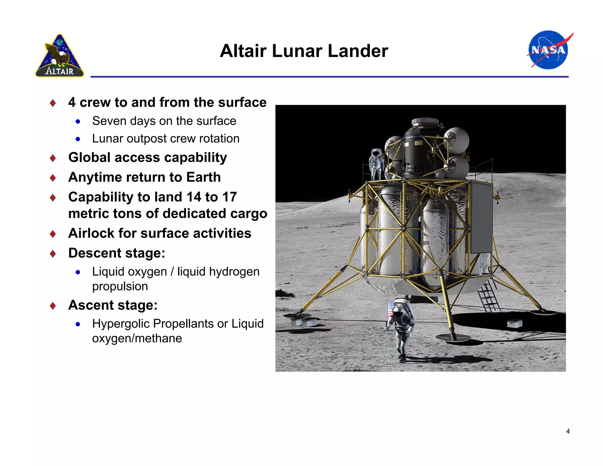
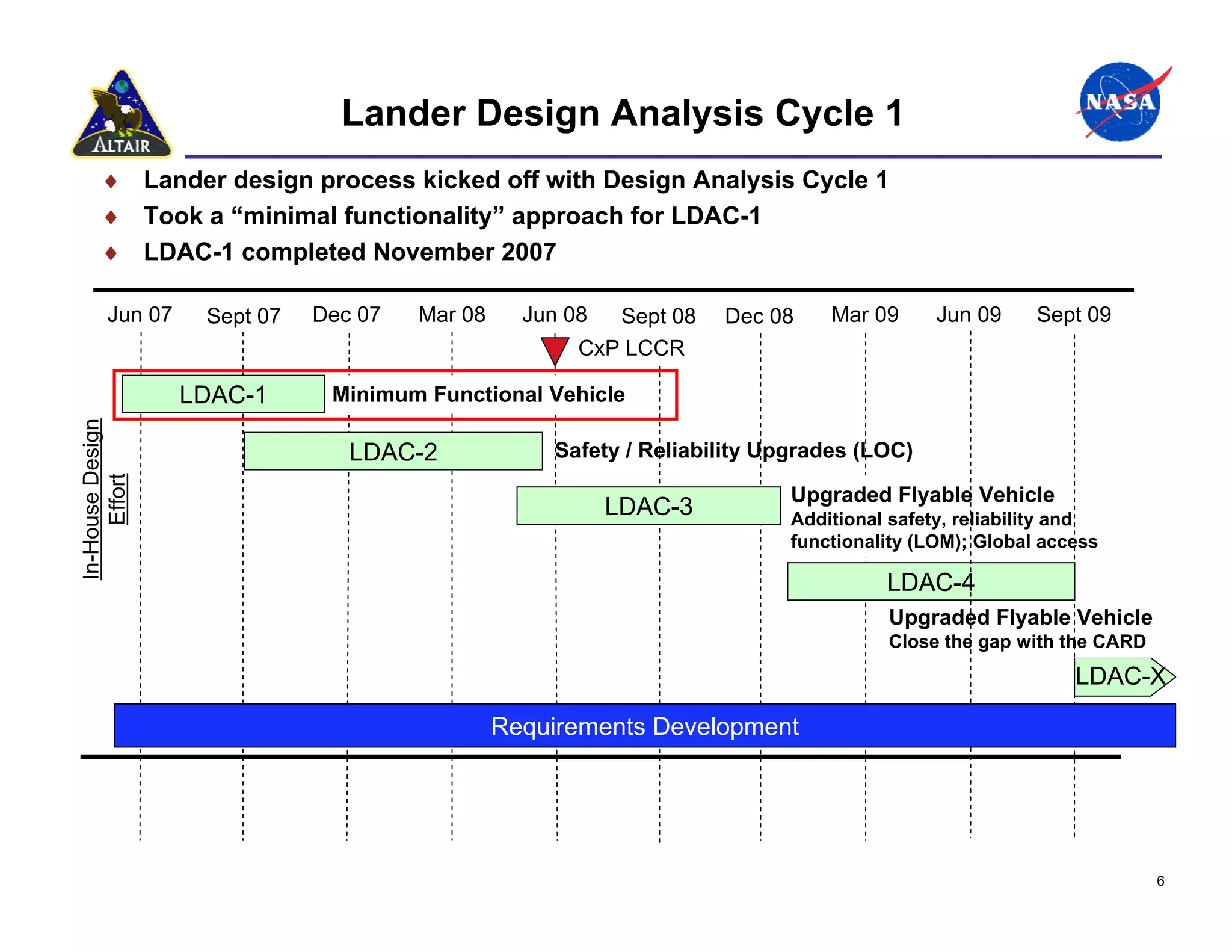
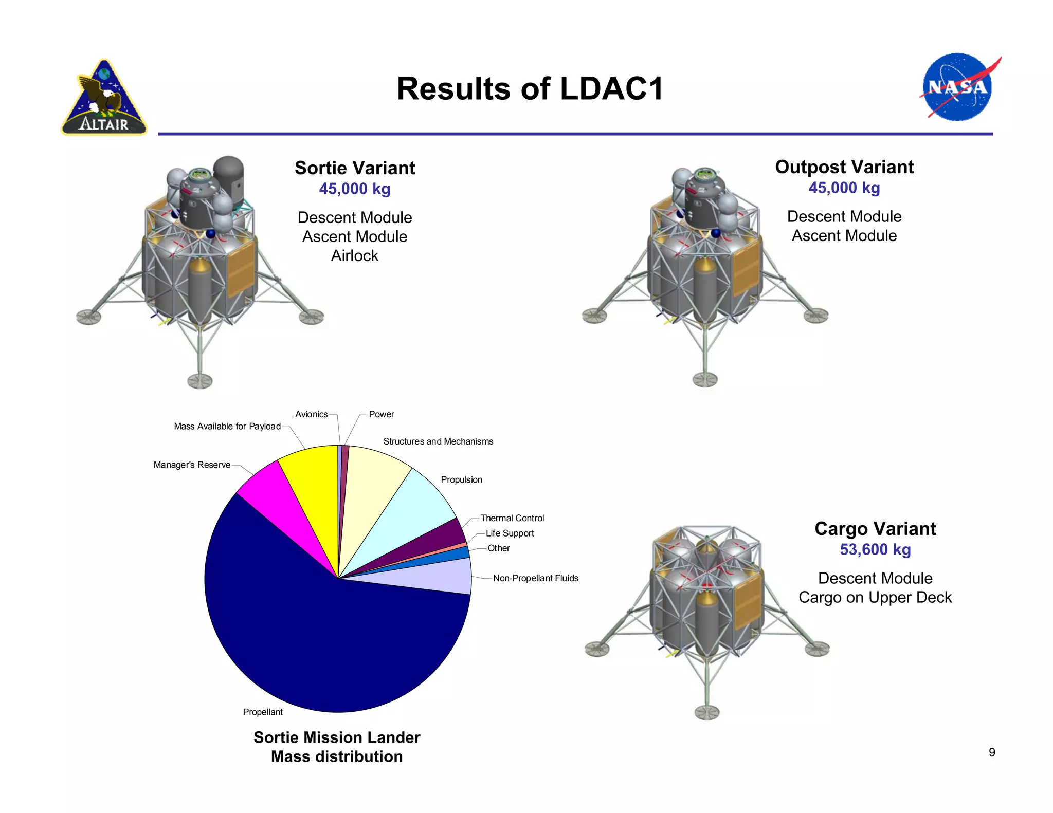
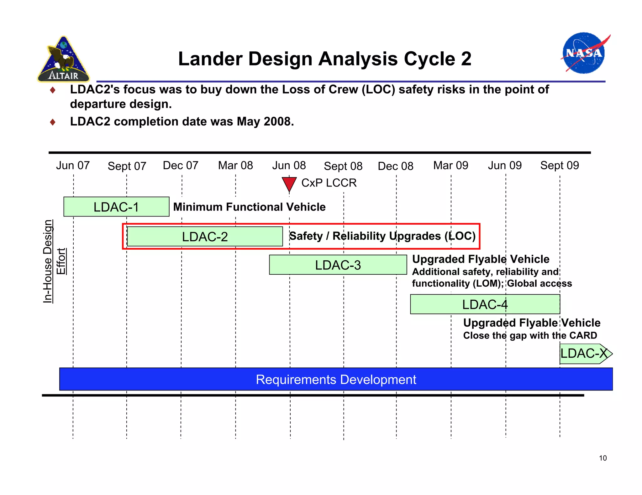
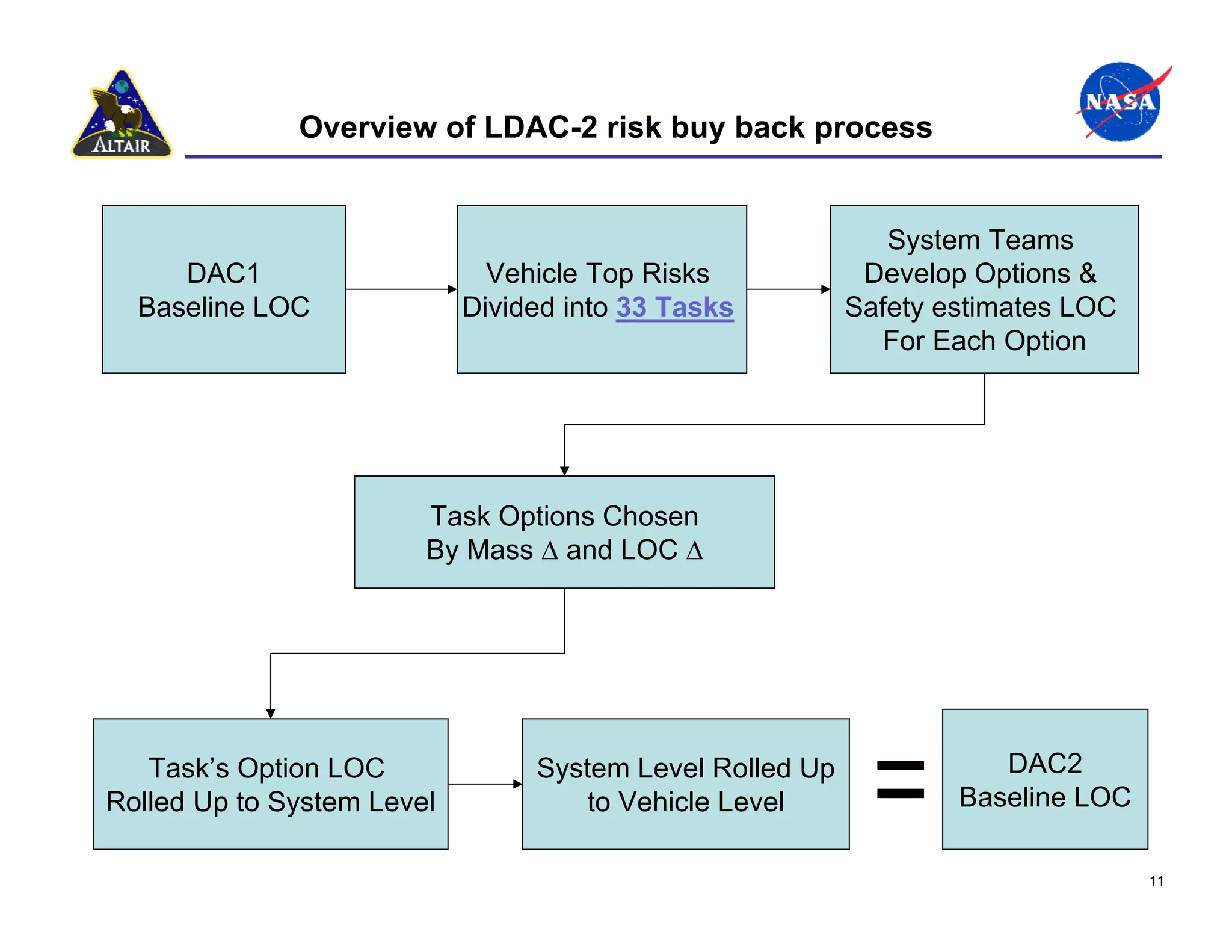
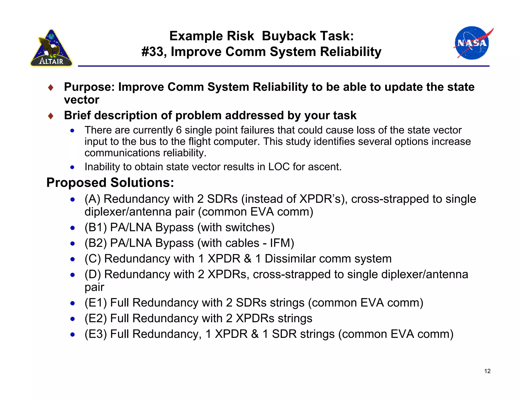
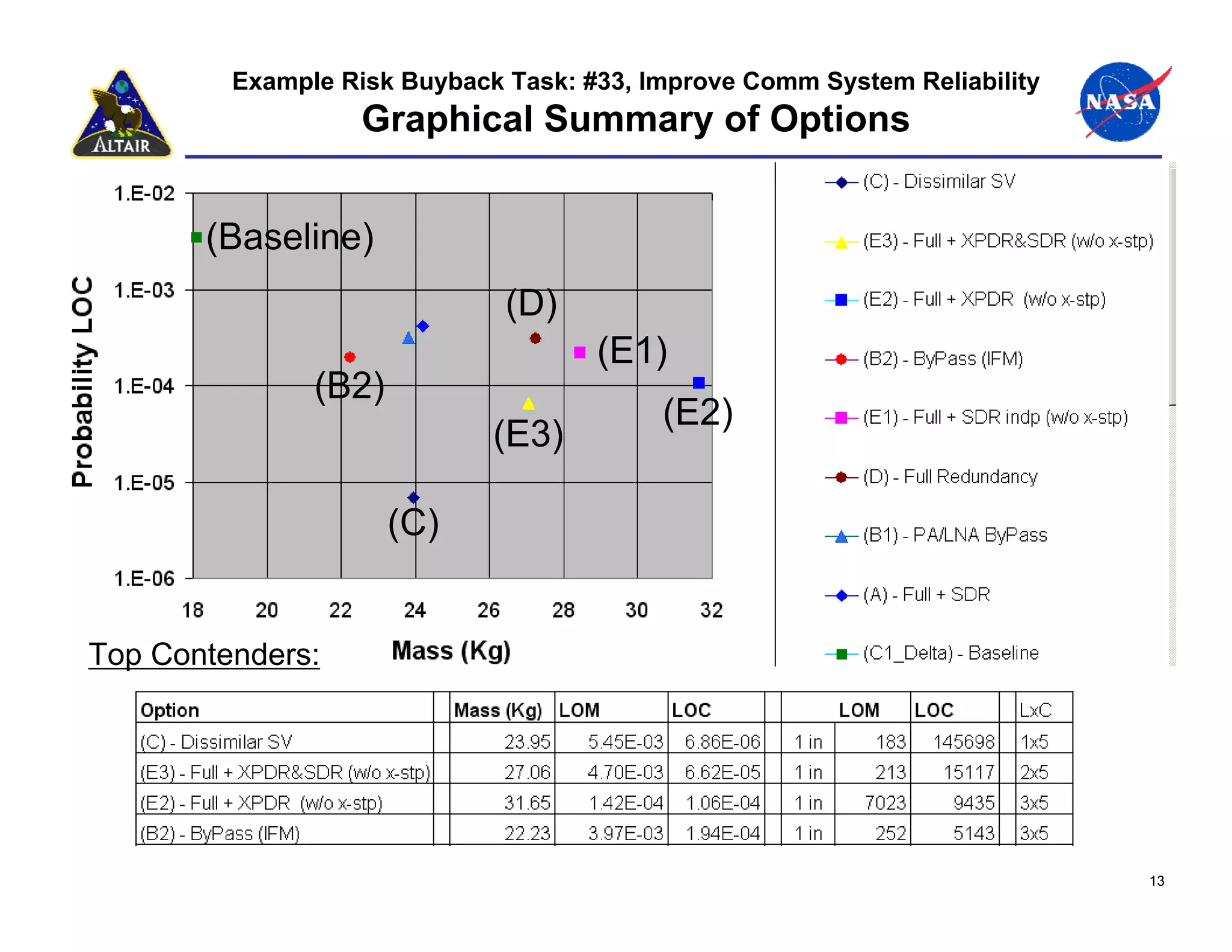
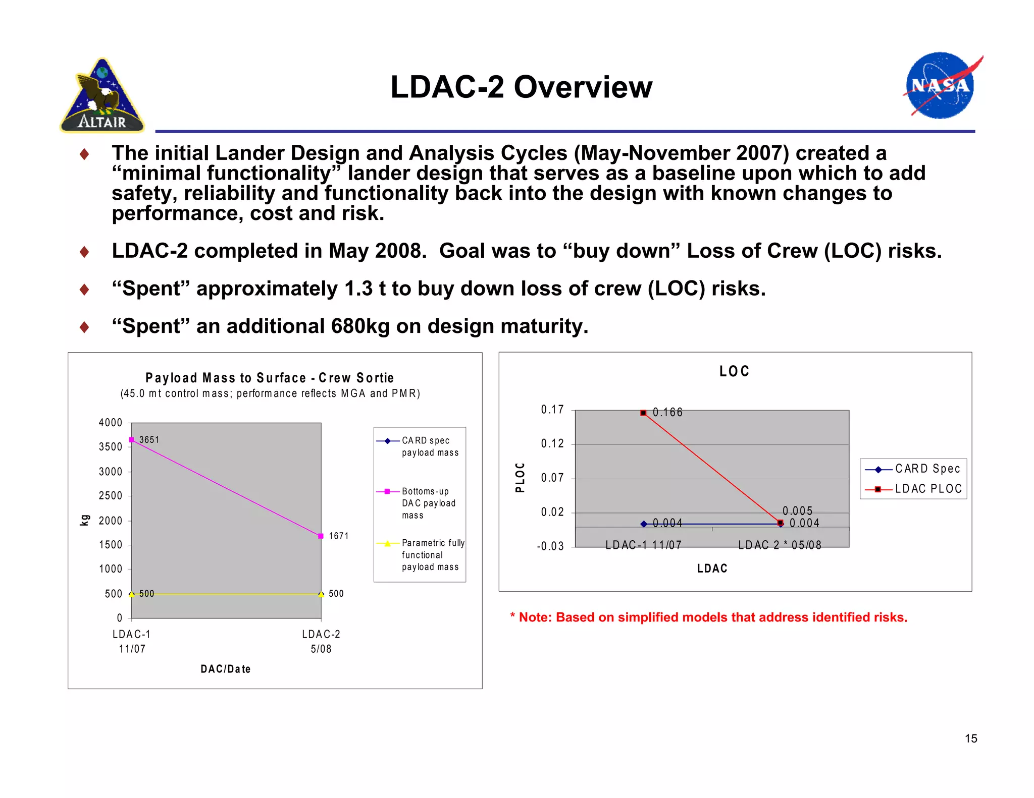
"Requirements Driven versus Risk Informed Design"
Requirements Driven versus
Risk Informed Design


Randy Rust
SR&QA Lead,
Altair Project
Johnson Space Center
                       Sensitive But Unclassified– For NASA Internal Use Only
Transportation Components of Program
                   Constellation
             Earth Departure
             Stage


                                             Crew Exploration
                                             Vehicle


Heavy Lift
Launch
Vehicle
                                    Lunar
                   Crew Launch      Lander
                   Vehicle


                                                                2
Typical Lunar Reference Mission

 MOON
                                 Vehicles are not to scale.

                                                                                          Ascent Stage
100 km                             Lander Performs LOI                                    Expended
Low Lunar
Orbit


                                                         Earth Departure
                                                         Stage Expended                     Service
Low                                                                                         Module
Earth                                                                                       Expended
Orbit
             EDS, Lander


                           CEV


                                                                           Direct Entry
                                                                           Land Landing

 EARTH
                                                                                                         3
Altair Lunar Lander

♦ 4 crew to and from the surface
   • Seven days on the surface
   • Lunar outpost crew rotation
♦ Global access capability
♦ Anytime return to Earth
♦ Capability to land 14 to 17
  metric tons of dedicated cargo
♦ Airlock for surface activities
♦ Descent stage:
   • Liquid oxygen / liquid hydrogen
     propulsion
♦ Ascent stage:
   • Hypergolic Propellants or Liquid
     oxygen/methane


                                                   4
Design Approach

♦ Project examined the multitude of concepts developed in the post-ESAS era, took
  lessons learned and began to develop a real design.

♦ Altair took a true risk informed design approach, starting with a minimum
  functionality design and adding from there to reduce risk.

♦ Lunar Design Analysis Cycle (LDAC) 1 developed a “minimum functional”
  vehicle.
    •   “Minimum Functionality” is a design philosophy that begins with a vehicle that will perform the
        mission, and no more than that
    •   Does not consider contingencies
    •   Does not have added redundancy (“single string” approach)
    •   Provides early, critical insight into the overall viability of the end-to-end architecture
    •   Provides a starting point to make informed cost/risk trades and consciously buy down risk
    •   A “Minimum Functionality” vehicle is NOT a design that would ever be contemplated as a
        “flyable” design!

♦ LDAC-2 determined the most significant contributors to loss of crew (LOC) and
  the optimum cost/risk trades to reduce those risks.

♦ LDAC-3 (current LDAC) is assessing biggest contributors to loss of mission
  (LOM) and optimum cost/risk trades to reduce those risks.

♦ Goal of the design process is to do enough real design work to understand and
  develop the requirements for SRR.
                                                                                                          5
Lander Design Analysis Cycle 1
      ♦ Lander design process kicked off with Design Analysis Cycle 1
      ♦ Took a “minimal functionality” approach for LDAC-1
      ♦ LDAC-1 completed November 2007

        Jun 07     Sept 07   Dec 07   Mar 08     Jun 08  Sept 08   Dec 08     Mar 09      Jun 09     Sept 09
                                                      CxP LCCR

                  LDAC-1      Minimum Functional Vehicle
In-House Design


                                LDAC-2             Safety / Reliability Upgrades (LOC)
     Effort


                                                                          Upgraded Flyable Vehicle
                                                          LDAC-3          Additional safety, reliability and
                                                                          functionality (LOM); Global access

                                                                                    LDAC-4
                                                                                    Upgraded Flyable Vehicle
                                                                                    Close the gap with the CARD
                                                                                                         LDAC-X

                                               Requirements Development


                                                                                                                  6
New Philosophy Needed

♦ For previous programs and projects, the general thought was to
  apply a failure tolerance philosophy
   •   One failure tolerant for loss of mission failures, and two failure tolerant to prevent loss of
       crew.
♦ For the Lander, where mass is extremely critical, this philosophy
  alone will not yield an optimal design solution.
   •   There are ways other than redundancy to improve reliability and still reduce the risk of loss
       of crew.
♦ We needed a new philosophy where we could develop a spacecraft
  that provides a required level of safety for the crew and is reliable
  enough to perform the mission.
   •   Defined the minimum set of functions necessary to accomplish the mission objectives.

   •   Made it work. Created the simplest & lowest mass conceptual design of the contemplated
       system.

   •   Consistent with NESC RP-06-108, Design, Development, Test, and Evaluation (DDT&E)
       Considerations for Safe and Reliable Human Rated Spacecraft Systems)


                                                                                                        7
LDAC-1 Starting Point

♦ ‘Hard’ Requirements
    •   4 Crew
    •   7 Day Sortie
    •   210 Day Outpost
    •   Airlock (implemented on sortie mission only)
    •   CxP transportation architecture
         − 8.4 meter shroud, TLI Loads, Lander performs LOI burn, CEV IRD, etc
    • Control Mass
         − Total Lander mass at TLI for crewed missions: 45,000 kg
         − Total Lander mass at TLI for cargo missions: 53,600 kg
♦ 3 DRMs with Mission Timelines and Functional Allocations
    • Sortie Mission to South Pole
         − 4 Crew / 7 Days on Surface / No support from surface assets
         − No restrictions on ‘when’ (accommodating eclipse periods)
    • Outpost Mission to South Pole
         − 4 Crew with Cargo Element (LAT Campaign option 2)
         − Outpost provides habitation on surface (down and out)
         − 210 Days with surface support (power)
    • Cargo Mission to South Pole
         − Short duration, large payload
♦ One Lander design, with variants (kits) if required for the different DRMs


                                                                                 8
Results of LDAC1

                                 Sortie Variant                                                  Outpost Variant
                                      45,000 kg                                                     45,000 kg
                                 Descent Module                                                   Descent Module
                                 Ascent Module                                                    Ascent Module
                                     Airlock


                                 Avionics   Power
    Mass Available for Payload
                                              Structures and Mechanisms

Manager's Reserve
                                                           Propulsion


                                                                    Thermal Control
                                                                        Life Support                 Cargo Variant
                                                                        Other                           53,600 kg
                                                                         Non-Propellant Fluids       Descent Module
                                                                                                   Cargo on Upper Deck


                    Propellant


                       Sortie Mission Lander
                         Mass distribution                                                                               9
Lander Design Analysis Cycle 2
    ♦             LDAC2's focus was to buy down the Loss of Crew (LOC) safety risks in the point of
                  departure design.
    ♦             LDAC2 completion date was May 2008.


        Jun 07          Sept 07   Dec 07   Mar 08     Jun 08  Sept 08   Dec 08     Mar 09      Jun 09     Sept 09
                                                           CxP LCCR

                     LDAC-1        Minimum Functional Vehicle
In-House Design


                                     LDAC-2             Safety / Reliability Upgrades (LOC)
     Effort


                                                                               Upgraded Flyable Vehicle
                                                               LDAC-3          Additional safety, reliability and
                                                                               functionality (LOM); Global access

                                                                                         LDAC-4
                                                                                         Upgraded Flyable Vehicle
                                                                                         Close the gap with the CARD
                                                                                                              LDAC-X

                                                    Requirements Development


                                                                                                                       10
Overview of LDAC-2 risk buy back process


                                                             System Teams
     DAC1                     Vehicle Top Risks            Develop Options &
  Baseline LOC              Divided into 33 Tasks         Safety estimates LOC
                                                            For Each Option


                        Task Options Chosen
                        By Mass ∆ and LOC ∆


   Task’s Option LOC             System Level Rolled Up              DAC2
Rolled Up to System Level            to Vehicle Level             Baseline LOC

                                                                                 11
Example Risk Buyback Task:
                   #33, Improve Comm System Reliability

♦ Purpose: Improve Comm System Reliability to be able to update the state
  vector
♦ Brief description of problem addressed by your task
    • There are currently 6 single point failures that could cause loss of the state vector
      input to the bus to the flight computer. This study identifies several options increase
      communications reliability.
    • Inability to obtain state vector results in LOC for ascent.
Proposed Solutions:
    • (A) Redundancy with 2 SDRs (instead of XPDR’s), cross-strapped to single
      diplexer/antenna pair (common EVA comm)
    • (B1) PA/LNA Bypass (with switches)
    • (B2) PA/LNA Bypass (with cables - IFM)
    • (C) Redundancy with 1 XPDR & 1 Dissimilar comm system
    • (D) Redundancy with 2 XPDRs, cross-strapped to single diplexer/antenna
      pair
    • (E1) Full Redundancy with 2 SDRs strings (common EVA comm)
    • (E2) Full Redundancy with 2 XPDRs strings
    • (E3) Full Redundancy, 1 XPDR & 1 SDR strings (common EVA comm)

                                                                                                12
Example Risk Buyback Task: #33, Improve Comm System Reliability
                   Graphical Summary of Options


       (Baseline)
                              (D)
                                     (E1)
               (B2)
                                          (E2)
                             (E3)

                      (C)


Top Contenders:


                                                                           13
Another Example: Active Thermal


                                L D A C 2 T h erm al S y s tem  O p tio n s  (D elta Mas s  V s . L O C ) vs. LOC)
                                                                              (Unallocated Differential
               1.00E ‐01
                                                                                                      B as eline L D A C 1_delta


                                                                                                      O ption A 1 dual internal loop


                                                                                                      O ption A 1f dual internal loop


                                                                                                      O ption B 1 dual c ritic al
                                                                                                      c omponents  

                                                                                                      O ption C 1 emergenc y  loop 


                                                                                                      O ption C 1f emergenc y  loop 
P robability


                                                                                                      O ption D 1 s ublimator driven
               1.00E ‐02
                                                                                                      c oldplate 

                                                                                                      O ption E 1 fully  redundant loops  


                                                                                                      O ption E 1fh fully  redundant loops  


                                                                                                      O ption E 1f fully  redundant loops  


                                                                                                      O ption F 1 s ingle loops  with
                                                                                                      redundant c omponents

                                                                                                      O ption G 1 mix  and matc h 


                                                                                                      O ption G 1f mix  and matc h 

               1.00E ‐03
                           0   100       200          300          400         500     600     700


                                               UnallocatedDe lta  Ma ss (K g .) (kg)
                                                           Differential

                                                                                                                                               14
LDAC-2 Overview
♦ The initial Lander Design and Analysis Cycles (May-November 2007) created a
  “minimal functionality” lander design that serves as a baseline upon which to add
  safety, reliability and functionality back into the design with known changes to
  performance, cost and risk.
♦ LDAC-2 completed in May 2008. Goal was to “buy down” Loss of Crew (LOC) risks.
♦ “Spent” approximately 1.3 t to buy down loss of crew (LOC) risks.
♦ “Spent” an additional 680kg on design maturity.

              P a y lo a d M a s s to S u rfa c e - C re w S o rtie                                                                        LO C
        (45.0 m t c ontrol m as s ; perform anc e reflec ts M G A and P M R )
                                                                                                          0 .1 7              0 .1 6 6
     4000
             3651                                                       CA RD s p e c                     0 .1 2
     3500                                                               p a y lo a d ma s s
                                                                                                                                                                       C AR D S p e c


                                                                                                P LO C
     3000
                                                                                                          0 .0 7
                                                                        B o tto ms -u p                                                                                L D AC P L O C
     2500
                                                                        DA C p a y lo a d
                                                                        ma s s                            0 .0 2                                          0 .0 0 5
     2000
kg


                                                                                                                              0 .0 0 4                      0 .0 0 4
                                                        1671
     1500                                                               Pa ra me tric f u lly            -0 .0 3   L D AC -1 1 1 /0 7           L D AC 2 * 0 5 /0 8
                                                                        f u n c tio n a l
     1000                                                               p a y lo a d ma s s                                              LDAC

      500    500                                        500

        0                                                                                       * Note: Based on simplified models that address identified risks.
       LD A C -1                                 LD A C -2
        11/07                                     5/08
                          D A C /D a te


                                                                                                                                                                                        15
Lessons Learned During Risk
                              Buy-down

♦ Full redundancy was usually heaviest, frequently NOT most effective for
  improving LOC
    • Conclusion may be different for LOM
♦ Quantitative risk tool was necessary to inform good design decisions
    • Always necessary to correlate engineering judgment with tool results
    • Tool forces team to reconsider
    • However, cannot rely solely on tool results. Must be able to technically explain
      decision.
♦ A risk tool the designers can interact with is a significant aid – improves
  tool and design
    • e.g., when a result did not correlate with engineering experience, designers could
      easily understand model in tool. Sometimes changed model and sometimes did not.
♦ Designing for minimum risk
    • results in lower weight design
    • is much harder and time consuming than simply adding redundancy
   • But, design team ends up much more intelligent on risk and design
     drivers
♦ Design for Minimum Risk is the way to go if you are trying to build a smart
  design team

                                                                                           16

Rust.randy

  • 1.
    "Requirements Driven versusRisk Informed Design" Requirements Driven versus Risk Informed Design Randy Rust SR&QA Lead, Altair Project Johnson Space Center Sensitive But Unclassified– For NASA Internal Use Only
  • 2.
    Transportation Components ofProgram Constellation Earth Departure Stage Crew Exploration Vehicle Heavy Lift Launch Vehicle Lunar Crew Launch Lander Vehicle 2
  • 3.
    Typical Lunar ReferenceMission MOON Vehicles are not to scale. Ascent Stage 100 km Lander Performs LOI Expended Low Lunar Orbit Earth Departure Stage Expended Service Low Module Earth Expended Orbit EDS, Lander CEV Direct Entry Land Landing EARTH 3
  • 4.
    Altair Lunar Lander ♦4 crew to and from the surface • Seven days on the surface • Lunar outpost crew rotation ♦ Global access capability ♦ Anytime return to Earth ♦ Capability to land 14 to 17 metric tons of dedicated cargo ♦ Airlock for surface activities ♦ Descent stage: • Liquid oxygen / liquid hydrogen propulsion ♦ Ascent stage: • Hypergolic Propellants or Liquid oxygen/methane 4
  • 5.
    Design Approach ♦ Projectexamined the multitude of concepts developed in the post-ESAS era, took lessons learned and began to develop a real design. ♦ Altair took a true risk informed design approach, starting with a minimum functionality design and adding from there to reduce risk. ♦ Lunar Design Analysis Cycle (LDAC) 1 developed a “minimum functional” vehicle. • “Minimum Functionality” is a design philosophy that begins with a vehicle that will perform the mission, and no more than that • Does not consider contingencies • Does not have added redundancy (“single string” approach) • Provides early, critical insight into the overall viability of the end-to-end architecture • Provides a starting point to make informed cost/risk trades and consciously buy down risk • A “Minimum Functionality” vehicle is NOT a design that would ever be contemplated as a “flyable” design! ♦ LDAC-2 determined the most significant contributors to loss of crew (LOC) and the optimum cost/risk trades to reduce those risks. ♦ LDAC-3 (current LDAC) is assessing biggest contributors to loss of mission (LOM) and optimum cost/risk trades to reduce those risks. ♦ Goal of the design process is to do enough real design work to understand and develop the requirements for SRR. 5
  • 6.
    Lander Design AnalysisCycle 1 ♦ Lander design process kicked off with Design Analysis Cycle 1 ♦ Took a “minimal functionality” approach for LDAC-1 ♦ LDAC-1 completed November 2007 Jun 07 Sept 07 Dec 07 Mar 08 Jun 08 Sept 08 Dec 08 Mar 09 Jun 09 Sept 09 CxP LCCR LDAC-1 Minimum Functional Vehicle In-House Design LDAC-2 Safety / Reliability Upgrades (LOC) Effort Upgraded Flyable Vehicle LDAC-3 Additional safety, reliability and functionality (LOM); Global access LDAC-4 Upgraded Flyable Vehicle Close the gap with the CARD LDAC-X Requirements Development 6
  • 7.
    New Philosophy Needed ♦For previous programs and projects, the general thought was to apply a failure tolerance philosophy • One failure tolerant for loss of mission failures, and two failure tolerant to prevent loss of crew. ♦ For the Lander, where mass is extremely critical, this philosophy alone will not yield an optimal design solution. • There are ways other than redundancy to improve reliability and still reduce the risk of loss of crew. ♦ We needed a new philosophy where we could develop a spacecraft that provides a required level of safety for the crew and is reliable enough to perform the mission. • Defined the minimum set of functions necessary to accomplish the mission objectives. • Made it work. Created the simplest & lowest mass conceptual design of the contemplated system. • Consistent with NESC RP-06-108, Design, Development, Test, and Evaluation (DDT&E) Considerations for Safe and Reliable Human Rated Spacecraft Systems) 7
  • 8.
    LDAC-1 Starting Point ♦‘Hard’ Requirements • 4 Crew • 7 Day Sortie • 210 Day Outpost • Airlock (implemented on sortie mission only) • CxP transportation architecture − 8.4 meter shroud, TLI Loads, Lander performs LOI burn, CEV IRD, etc • Control Mass − Total Lander mass at TLI for crewed missions: 45,000 kg − Total Lander mass at TLI for cargo missions: 53,600 kg ♦ 3 DRMs with Mission Timelines and Functional Allocations • Sortie Mission to South Pole − 4 Crew / 7 Days on Surface / No support from surface assets − No restrictions on ‘when’ (accommodating eclipse periods) • Outpost Mission to South Pole − 4 Crew with Cargo Element (LAT Campaign option 2) − Outpost provides habitation on surface (down and out) − 210 Days with surface support (power) • Cargo Mission to South Pole − Short duration, large payload ♦ One Lander design, with variants (kits) if required for the different DRMs 8
  • 9.
    Results of LDAC1 Sortie Variant Outpost Variant 45,000 kg 45,000 kg Descent Module Descent Module Ascent Module Ascent Module Airlock Avionics Power Mass Available for Payload Structures and Mechanisms Manager's Reserve Propulsion Thermal Control Life Support Cargo Variant Other 53,600 kg Non-Propellant Fluids Descent Module Cargo on Upper Deck Propellant Sortie Mission Lander Mass distribution 9
  • 10.
    Lander Design AnalysisCycle 2 ♦ LDAC2's focus was to buy down the Loss of Crew (LOC) safety risks in the point of departure design. ♦ LDAC2 completion date was May 2008. Jun 07 Sept 07 Dec 07 Mar 08 Jun 08 Sept 08 Dec 08 Mar 09 Jun 09 Sept 09 CxP LCCR LDAC-1 Minimum Functional Vehicle In-House Design LDAC-2 Safety / Reliability Upgrades (LOC) Effort Upgraded Flyable Vehicle LDAC-3 Additional safety, reliability and functionality (LOM); Global access LDAC-4 Upgraded Flyable Vehicle Close the gap with the CARD LDAC-X Requirements Development 10
  • 11.
    Overview of LDAC-2risk buy back process System Teams DAC1 Vehicle Top Risks Develop Options & Baseline LOC Divided into 33 Tasks Safety estimates LOC For Each Option Task Options Chosen By Mass ∆ and LOC ∆ Task’s Option LOC System Level Rolled Up DAC2 Rolled Up to System Level to Vehicle Level Baseline LOC 11
  • 12.
    Example Risk BuybackTask: #33, Improve Comm System Reliability ♦ Purpose: Improve Comm System Reliability to be able to update the state vector ♦ Brief description of problem addressed by your task • There are currently 6 single point failures that could cause loss of the state vector input to the bus to the flight computer. This study identifies several options increase communications reliability. • Inability to obtain state vector results in LOC for ascent. Proposed Solutions: • (A) Redundancy with 2 SDRs (instead of XPDR’s), cross-strapped to single diplexer/antenna pair (common EVA comm) • (B1) PA/LNA Bypass (with switches) • (B2) PA/LNA Bypass (with cables - IFM) • (C) Redundancy with 1 XPDR & 1 Dissimilar comm system • (D) Redundancy with 2 XPDRs, cross-strapped to single diplexer/antenna pair • (E1) Full Redundancy with 2 SDRs strings (common EVA comm) • (E2) Full Redundancy with 2 XPDRs strings • (E3) Full Redundancy, 1 XPDR & 1 SDR strings (common EVA comm) 12
  • 13.
    Example Risk BuybackTask: #33, Improve Comm System Reliability Graphical Summary of Options (Baseline) (D) (E1) (B2) (E2) (E3) (C) Top Contenders: 13
  • 14.
    Another Example: ActiveThermal L D A C 2 T h erm al S y s tem  O p tio n s  (D elta Mas s  V s . L O C ) vs. LOC) (Unallocated Differential 1.00E ‐01 B as eline L D A C 1_delta O ption A 1 dual internal loop O ption A 1f dual internal loop O ption B 1 dual c ritic al c omponents   O ption C 1 emergenc y  loop  O ption C 1f emergenc y  loop  P robability O ption D 1 s ublimator driven 1.00E ‐02 c oldplate  O ption E 1 fully  redundant loops   O ption E 1fh fully  redundant loops   O ption E 1f fully  redundant loops   O ption F 1 s ingle loops  with redundant c omponents O ption G 1 mix  and matc h  O ption G 1f mix  and matc h  1.00E ‐03 0 100 200 300 400 500 600 700 UnallocatedDe lta  Ma ss (K g .) (kg) Differential 14
  • 15.
    LDAC-2 Overview ♦ Theinitial Lander Design and Analysis Cycles (May-November 2007) created a “minimal functionality” lander design that serves as a baseline upon which to add safety, reliability and functionality back into the design with known changes to performance, cost and risk. ♦ LDAC-2 completed in May 2008. Goal was to “buy down” Loss of Crew (LOC) risks. ♦ “Spent” approximately 1.3 t to buy down loss of crew (LOC) risks. ♦ “Spent” an additional 680kg on design maturity. P a y lo a d M a s s to S u rfa c e - C re w S o rtie LO C (45.0 m t c ontrol m as s ; perform anc e reflec ts M G A and P M R ) 0 .1 7 0 .1 6 6 4000 3651 CA RD s p e c 0 .1 2 3500 p a y lo a d ma s s C AR D S p e c P LO C 3000 0 .0 7 B o tto ms -u p L D AC P L O C 2500 DA C p a y lo a d ma s s 0 .0 2 0 .0 0 5 2000 kg 0 .0 0 4 0 .0 0 4 1671 1500 Pa ra me tric f u lly -0 .0 3 L D AC -1 1 1 /0 7 L D AC 2 * 0 5 /0 8 f u n c tio n a l 1000 p a y lo a d ma s s LDAC 500 500 500 0 * Note: Based on simplified models that address identified risks. LD A C -1 LD A C -2 11/07 5/08 D A C /D a te 15
  • 16.
    Lessons Learned DuringRisk Buy-down ♦ Full redundancy was usually heaviest, frequently NOT most effective for improving LOC • Conclusion may be different for LOM ♦ Quantitative risk tool was necessary to inform good design decisions • Always necessary to correlate engineering judgment with tool results • Tool forces team to reconsider • However, cannot rely solely on tool results. Must be able to technically explain decision. ♦ A risk tool the designers can interact with is a significant aid – improves tool and design • e.g., when a result did not correlate with engineering experience, designers could easily understand model in tool. Sometimes changed model and sometimes did not. ♦ Designing for minimum risk • results in lower weight design • is much harder and time consuming than simply adding redundancy • But, design team ends up much more intelligent on risk and design drivers ♦ Design for Minimum Risk is the way to go if you are trying to build a smart design team 16