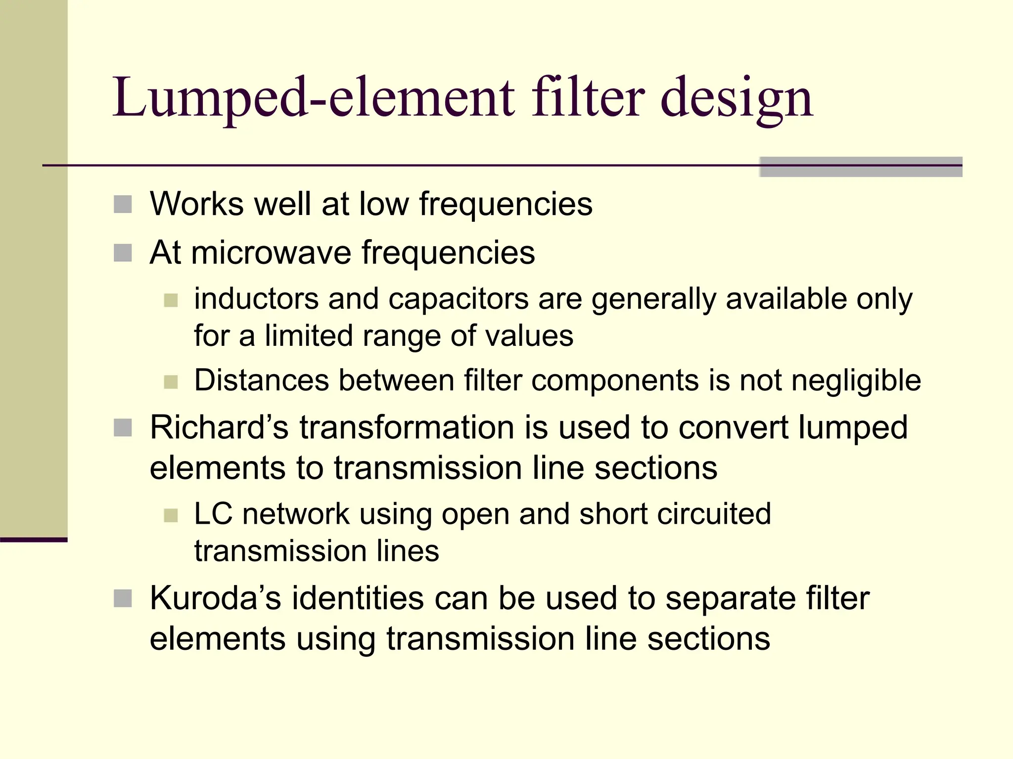
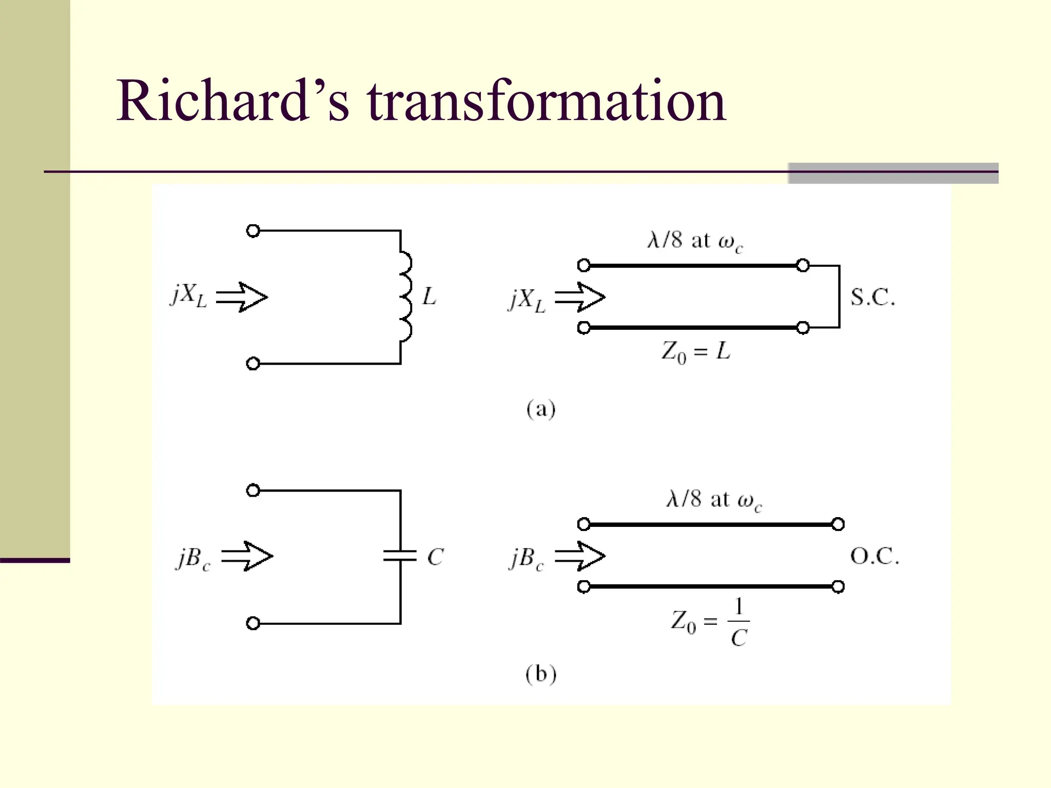
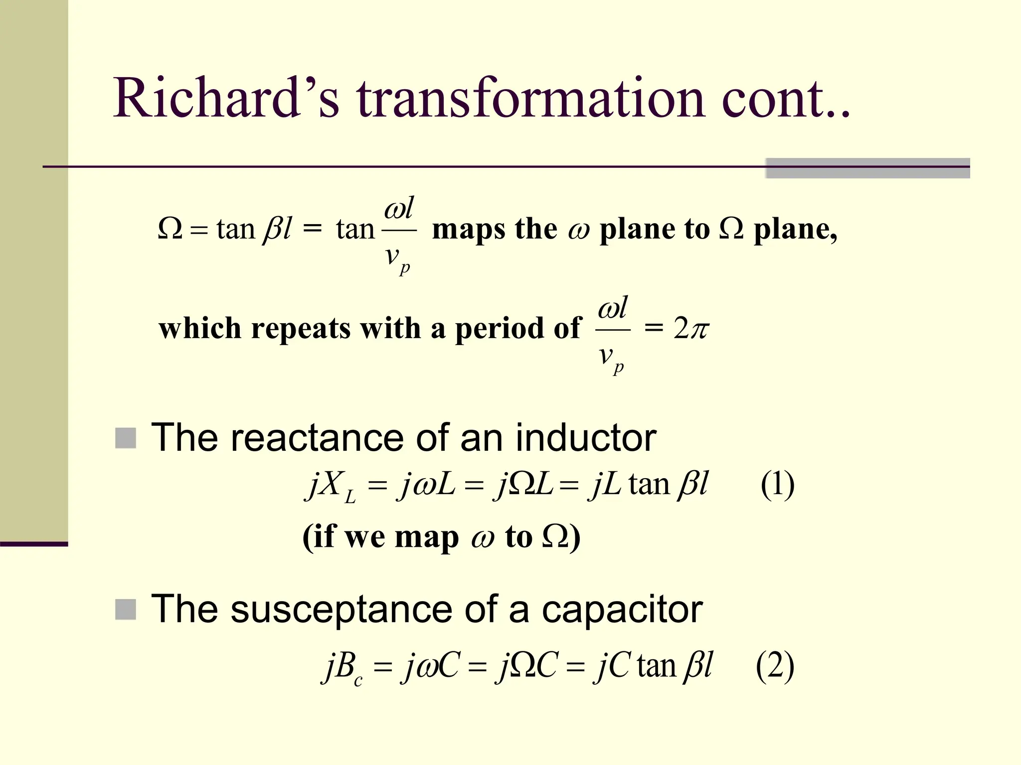
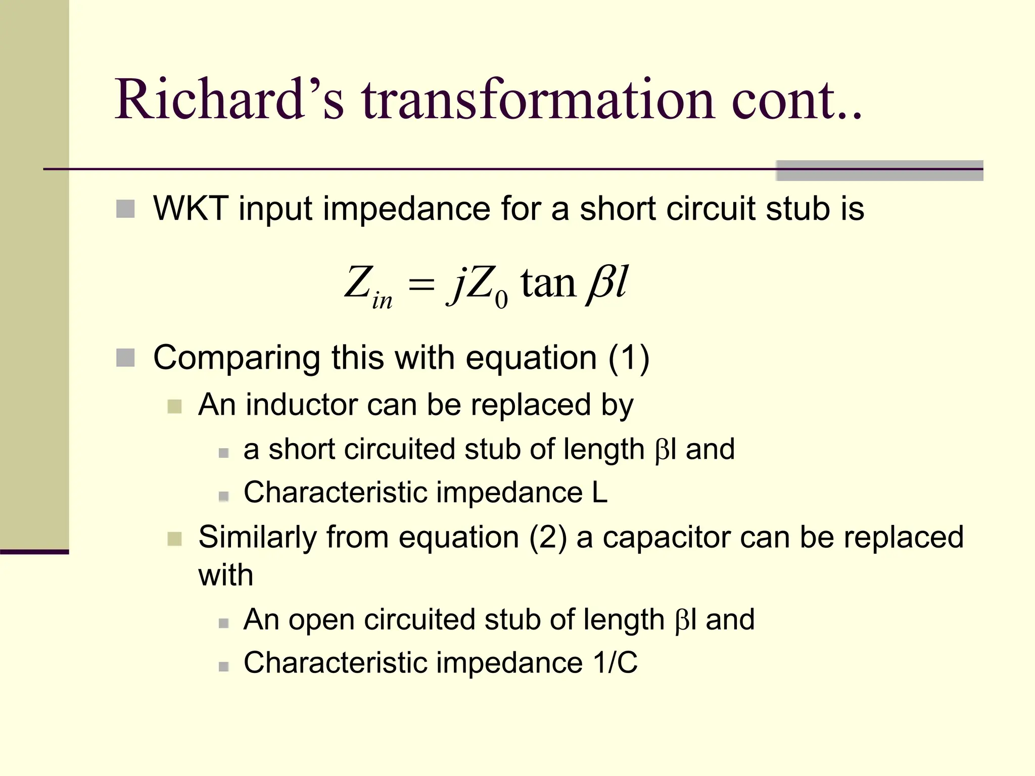
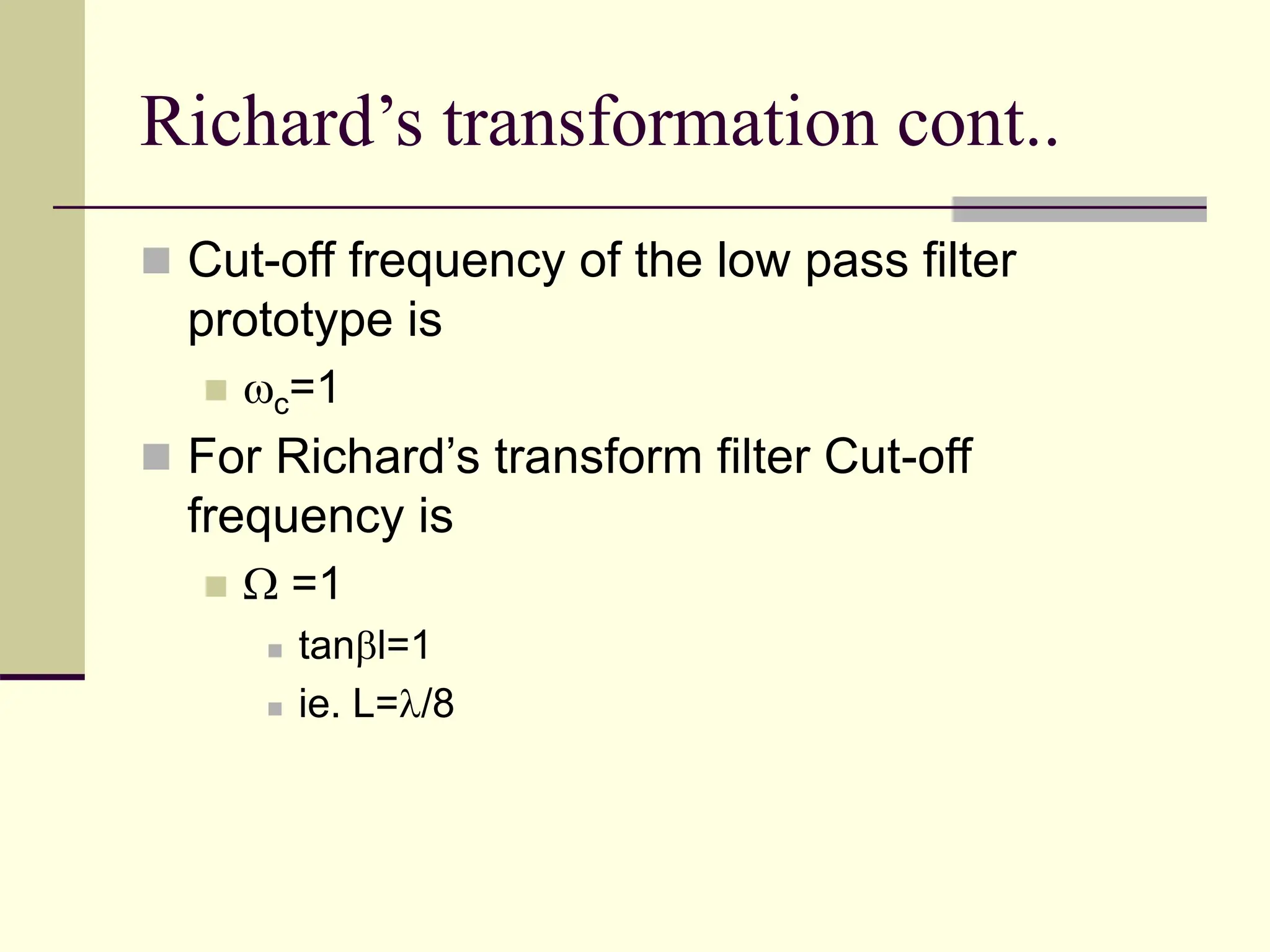
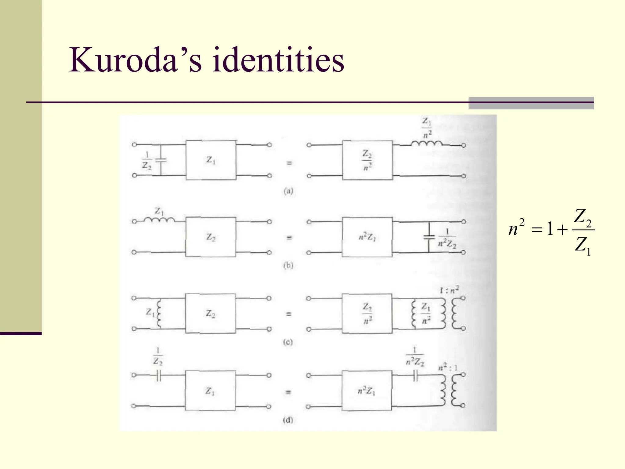
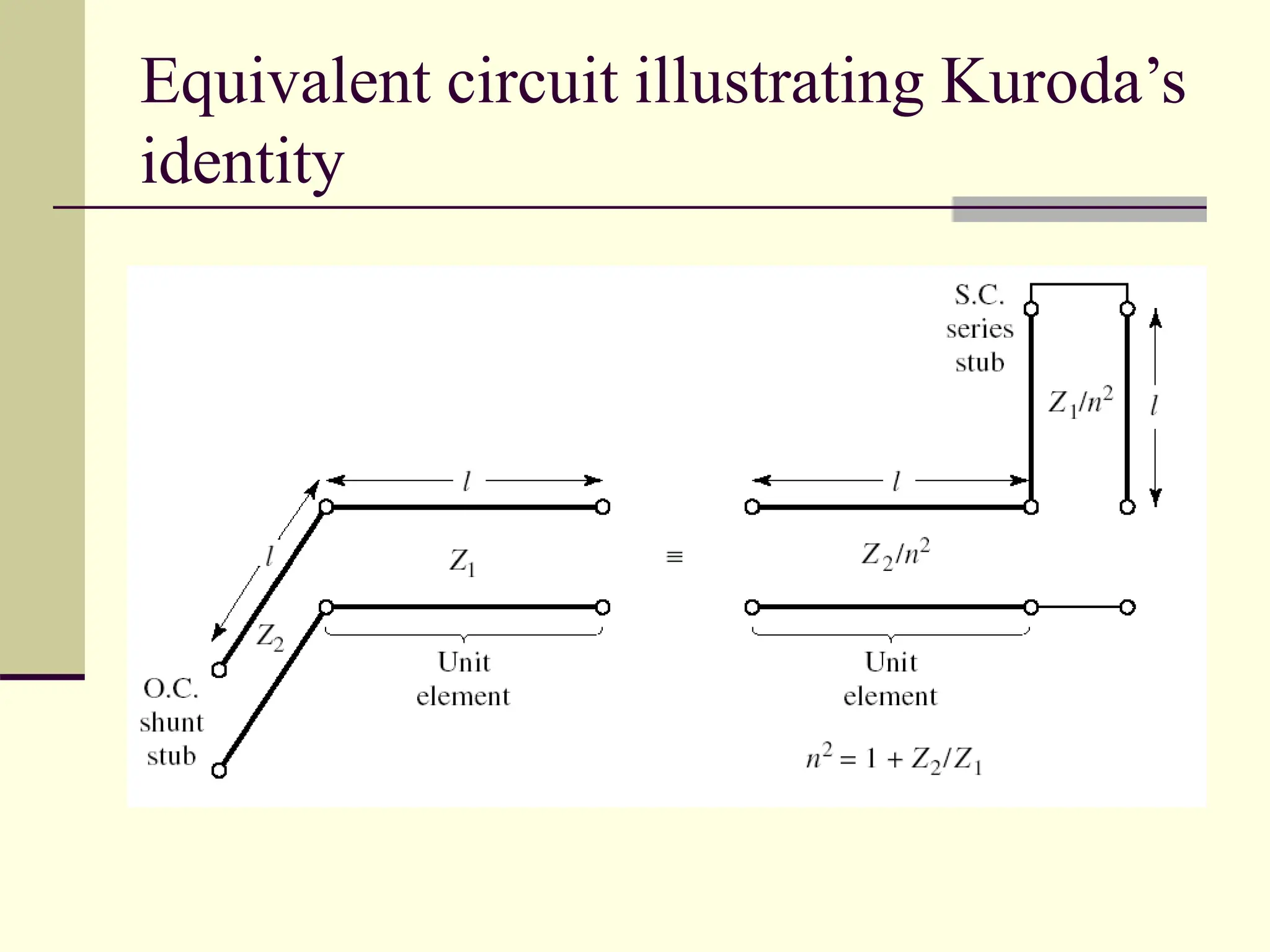
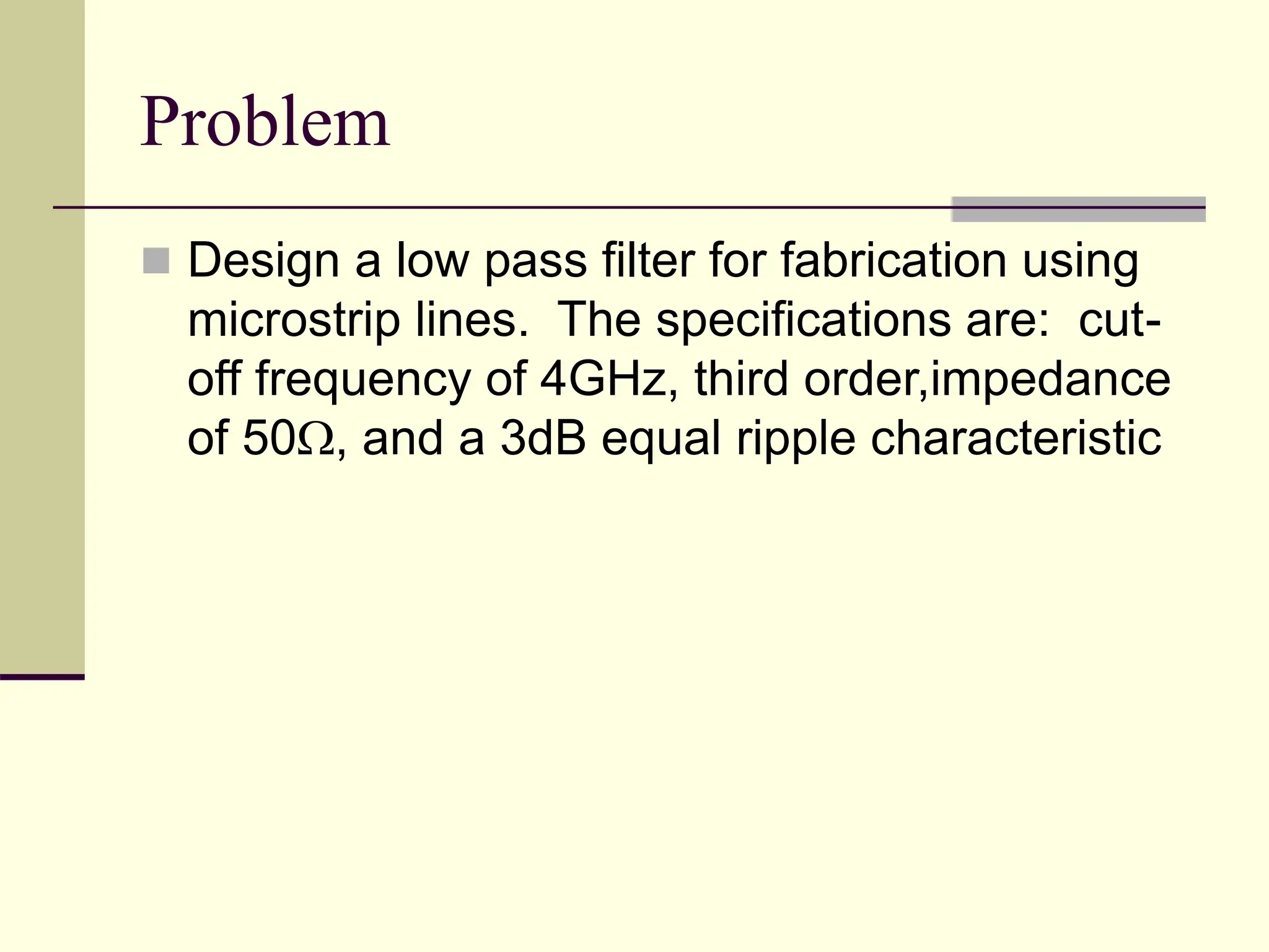
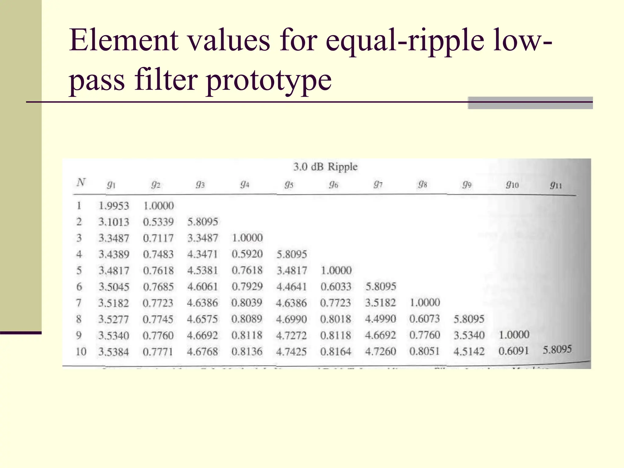
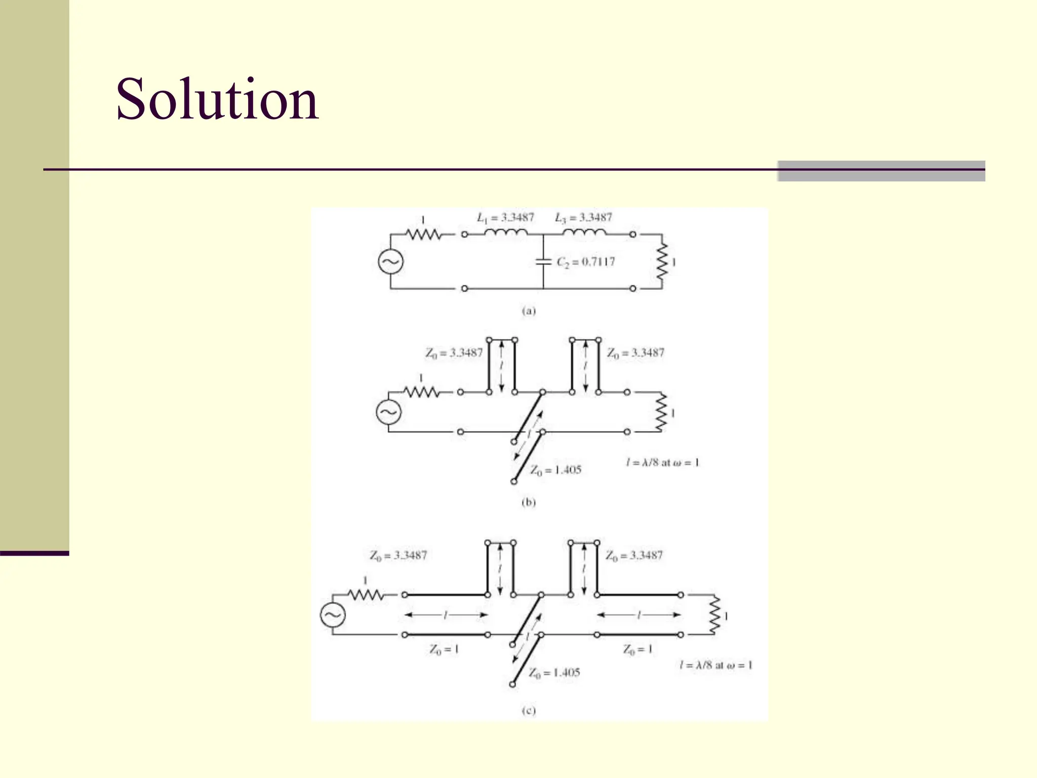
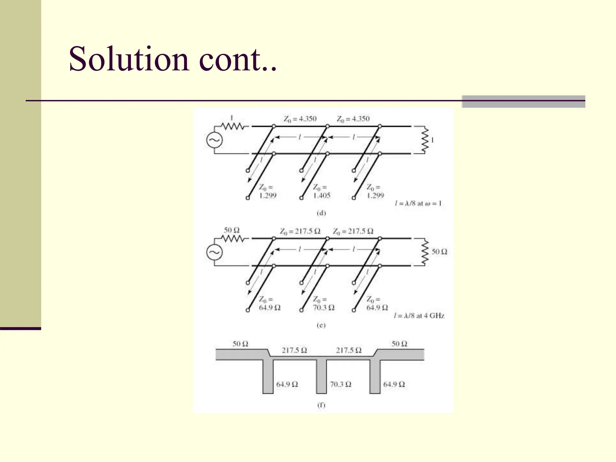
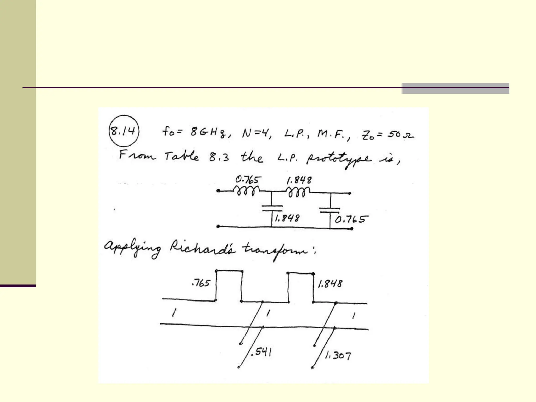
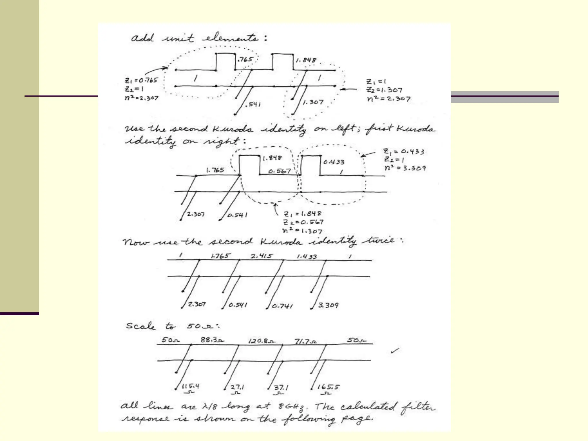
Richards Transformation
method
Class 29 & 30
Lumped-element filter design
 Works well at low frequencies
 At microwave frequencies
 inductors and capacitors are generally available only
for a limited range of values
 Distances between filter components is not negligible
 Richard’s transformation is used to convert lumped
elements to transmission line sections
 LC network using open and short circuited
transmission lines
 Kuroda’s identities can be used to separate filter
elements using transmission line sections
Richard’s transformation
Richard’s transformation cont..
 The reactance of an inductor
 The susceptance of a capacitor
tan tan
2
= maps the plane to plane,
which repeats with a period of =
p
p
l
l
v
l
v

 


  
tan (1)
(if we map to )
L
jX j L j L jL l
 

   

tan (2)
c
jB j C j C jC l
 
   
Richard’s transformation cont..
 WKT input impedance for a short circuit stub is
 Comparing this with equation (1)
 An inductor can be replaced by
 a short circuited stub of length l and
 Characteristic impedance L
 Similarly from equation (2) a capacitor can be replaced
with
 An open circuited stub of length l and
 Characteristic impedance 1/C
0 tan
in
Z jZ l


Richard’s transformation cont..
 Cut-off frequency of the low pass filter
prototype is
 c=1
 For Richard’s transform filter Cut-off
frequency is
  =1
 tanl=1
 ie. L=/8
Kuroda’s identities
2 2
1
1
Z
n
Z
 
Kuroda’s identities cont..
 Physically separate transmission line stubs
 Using unit elements
 an additional transmission line section of length
/8 at c
 Transform series stubs into shunt stubs
 Change impractical characteristic
impedances into more realizable ones
Equivalent circuit illustrating Kuroda’s
identity
Problem
 Design a low pass filter for fabrication using
microstrip lines. The specifications are: cut-
off frequency of 4GHz, third order,impedance
of 50, and a 3dB equal ripple characteristic
Element values for equal-ripple low-
pass filter prototype
Solution
Solution cont..
Problems
 Design a three-element maximally flat low-
pass filter with its cut-off frequency as 1GHz.
It is to be used between a 50 load and a
generator with its internal impedance at 50
 Design a low pass fourth order maximally flat
filter using only shunt stubs. The cut-off
frequency is 8GHz and the impedance is 50
richard transformation method its used to so many things.ppt

richard transformation method its used to so many things.ppt

  • 1.
  • 2.
    Lumped-element filter design Works well at low frequencies  At microwave frequencies  inductors and capacitors are generally available only for a limited range of values  Distances between filter components is not negligible  Richard’s transformation is used to convert lumped elements to transmission line sections  LC network using open and short circuited transmission lines  Kuroda’s identities can be used to separate filter elements using transmission line sections
  • 3.
  • 4.
    Richard’s transformation cont.. The reactance of an inductor  The susceptance of a capacitor tan tan 2 = maps the plane to plane, which repeats with a period of = p p l l v l v         tan (1) (if we map to ) L jX j L j L jL l         tan (2) c jB j C j C jC l      
  • 5.
    Richard’s transformation cont.. WKT input impedance for a short circuit stub is  Comparing this with equation (1)  An inductor can be replaced by  a short circuited stub of length l and  Characteristic impedance L  Similarly from equation (2) a capacitor can be replaced with  An open circuited stub of length l and  Characteristic impedance 1/C 0 tan in Z jZ l  
  • 6.
    Richard’s transformation cont.. Cut-off frequency of the low pass filter prototype is  c=1  For Richard’s transform filter Cut-off frequency is   =1  tanl=1  ie. L=/8
  • 7.
  • 8.
    Kuroda’s identities cont.. Physically separate transmission line stubs  Using unit elements  an additional transmission line section of length /8 at c  Transform series stubs into shunt stubs  Change impractical characteristic impedances into more realizable ones
  • 9.
  • 10.
    Problem  Design alow pass filter for fabrication using microstrip lines. The specifications are: cut- off frequency of 4GHz, third order,impedance of 50, and a 3dB equal ripple characteristic
  • 11.
    Element values forequal-ripple low- pass filter prototype
  • 12.
  • 13.
  • 14.
    Problems  Design athree-element maximally flat low- pass filter with its cut-off frequency as 1GHz. It is to be used between a 50 load and a generator with its internal impedance at 50  Design a low pass fourth order maximally flat filter using only shunt stubs. The cut-off frequency is 8GHz and the impedance is 50