Download as PDF, PPTX
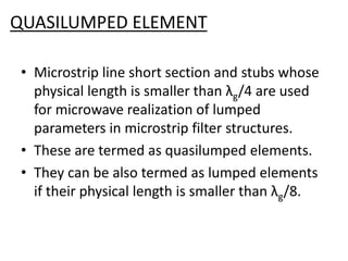
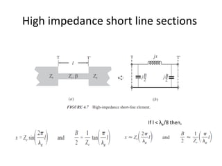
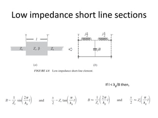
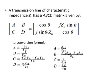
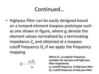
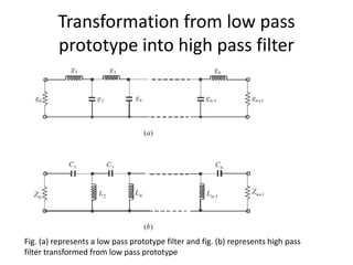
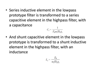
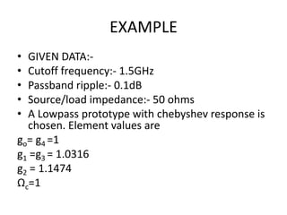
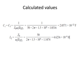
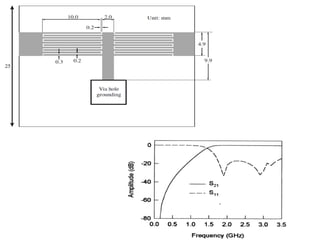


This document discusses the design of quasilumped element high-pass filters using microstrip lines. It explains that microstrip short sections and stubs whose length is less than a quarter wavelength can approximate lumped elements. These are called quasilumped elements. It then provides the ABCD matrix for a transmission line and discusses how a high-pass filter can be designed by transforming the element values of a low-pass filter prototype using a frequency mapping equation. An example is given of designing a high-pass filter with specific parameters using a Chebyshev low-pass prototype filter.


