Download as PDF, PPTX
![Scoping Out CA
CA(Carrier Aggregation) is a technique used to
combine multiple Long‐Term Evolution (LTE)
component carriers (CCs) across the available spec-
trum to[1] :
Support wider bandwidth signals
Increase data rates
Improve network performance
As of today, up to five CCs can be allocated for 100 MHz
of bandwidth per user[1].
2](https://image.slidesharecdn.com/abcsofcarrieraggregation-180420073403/75/ABCs-of-Carrier-Aggregation-2-2048.jpg)
![Scoping Out CA
Mobile carriers can use CA to increase performance on
their networks, as shown below[1] :
100%
improvement in
physical layer
For example, AT&T’s median download speed in
Chicago increased from 10.69 Mbps to 15.18 Mbps
when AT&T started using CA there[1].
3](https://image.slidesharecdn.com/abcsofcarrieraggregation-180420073403/75/ABCs-of-Carrier-Aggregation-3-2048.jpg)
![Exploring Data Rate Evolution
Carriers will use CA technology to combine spectrum in
low‐, mid‐, and high‐band frequencies to boost speed
and capacity, and the modem class are shown as
below[1]:
Any bandwidth above 20 MHz requires at least two‐CC CA
Any bandwidth above 40 MHz requires at least three‐CC CA
Any bandwidth above 60 MHz requires at least four‐CC CA4](https://image.slidesharecdn.com/abcsofcarrieraggregation-180420073403/75/ABCs-of-Carrier-Aggregation-4-2048.jpg)
![Exploring Data Rate Evolution
With CA, Downlink data rate evolution is shown as
below[1]:
5](https://image.slidesharecdn.com/abcsofcarrieraggregation-180420073403/75/ABCs-of-Carrier-Aggregation-5-2048.jpg)
![Relating FDD and TDD to CA
Each CC in FDD or TDD can have a bandwidth of 1.4, 3,
5, 10, 15, or 20 MHz[1,2].
For FDD, the CC number in DL should be larger than or
equal to which in UL[1,2].
For TDD, the CC number in DL should be equal to which
in UL[1,2].
3GPP defined FDD‐TDD aggregation in Release 12,
which allows either FDD or TDD as the primary cell.
FDD‐TDD aggregation can provide an attractive
combination of low‐band FDD for good coverage and
high‐band TDD with more spectrum for higher data
rates[1].
6](https://image.slidesharecdn.com/abcsofcarrieraggregation-180420073403/75/ABCs-of-Carrier-Aggregation-6-2048.jpg)
![Relating FDD and TDD to CA
But data rate differences arise depending on whether a
carrier is using FDD‐LTE or TDD‐LTE[1].
As shown above, obviously, both in DL and UL, the data
rate in FDD is always higher than TDD in all
bandwidth[1].
7](https://image.slidesharecdn.com/abcsofcarrieraggregation-180420073403/75/ABCs-of-Carrier-Aggregation-7-2048.jpg)
![Joining Adjacent CCs in the Same Band
The simplest CA deployment scenario, intra‐band
contiguous CA, aggregates multiple adjacent CCs in a
single operating band[1].
Unfortunately, aggregating contiguous CCs is not
always possible. However, as new spectrum bands
(such as 3.5 GHz and 600 MHz) are allocated in the
future, intra‐band contiguous CA may become more
common[1].
8](https://image.slidesharecdn.com/abcsofcarrieraggregation-180420073403/75/ABCs-of-Carrier-Aggregation-8-2048.jpg)
![Bringing Separate CCs Together in the Same Band
As shown below, Intra‐band non‐contiguous CA is a
common deployment scenario, aggregating multiple
separated CCs in a single operating band[1].
9](https://image.slidesharecdn.com/abcsofcarrieraggregation-180420073403/75/ABCs-of-Carrier-Aggregation-9-2048.jpg)
![Combining Multiple CCs in Different Bands
Inter‐band CA, shown in below, aggregates multiple
CCs in different operating bands (the CCs aggregated
in each band can be contiguous or non‐contiguous)[1].
10](https://image.slidesharecdn.com/abcsofcarrieraggregation-180420073403/75/ABCs-of-Carrier-Aggregation-10-2048.jpg)
![Understanding Downlink Challenges
Downlink CA challenges include[1]:
Downlink sensitivity
Harmonic generation
Desense challenges in CA RF radio design
11](https://image.slidesharecdn.com/abcsofcarrieraggregation-180420073403/75/ABCs-of-Carrier-Aggregation-11-2048.jpg)
![ANT
Matching
PA
Duplexer
LNA
Downlink sensitivity
In a non‐CA, single carrier FDD (frequency division
duplex) scenario, an RF duplexer ensures that
transmissions on the uplink do not interfere with
reception on the downlink[1].
Connecting two duplexer paths can affect the filter
characteristic of both duplexers, thereby causing you
to lose transmit and receive path isolation required to
operate at system sensitivity[1,2].
12](https://image.slidesharecdn.com/abcsofcarrieraggregation-180420073403/75/ABCs-of-Carrier-Aggregation-12-2048.jpg)
![Downlink sensitivity
Therefore, for CA case[2] :
Single Antenna : to insert diplexer (LB/HB combination) or
phase shifter(LB/LB, HB/HB combination).
Multiple Antennas : No diplexer or phase shifter.
13](https://image.slidesharecdn.com/abcsofcarrieraggregation-180420073403/75/ABCs-of-Carrier-Aggregation-13-2048.jpg)
![Downlink sensitivity
In addition, for CA case, you need quadplexer if you
want[2] :
Single Antenna
No diplexer, no phase shifter
14](https://image.slidesharecdn.com/abcsofcarrieraggregation-180420073403/75/ABCs-of-Carrier-Aggregation-14-2048.jpg)
![Harmonic generation
When the harmonic of a transmit signal falls in the
receive band of a paired CA band, the sensitivity is
degraded because the harmonic level in that band is
high enough to prevent the desired signal from being
detected[1].
15](https://image.slidesharecdn.com/abcsofcarrieraggregation-180420073403/75/ABCs-of-Carrier-Aggregation-15-2048.jpg)
![Harmonic generation
Thus, for LB/MB(HB) combination CA, harmonics
filtering is required[1].
As shown above, in addition to inherent
duplexer(comprising TX BPF) and diplexer(comprising
LPF), we have to insert an additional LPF in LB path[1].
16](https://image.slidesharecdn.com/abcsofcarrieraggregation-180420073403/75/ABCs-of-Carrier-Aggregation-16-2048.jpg)
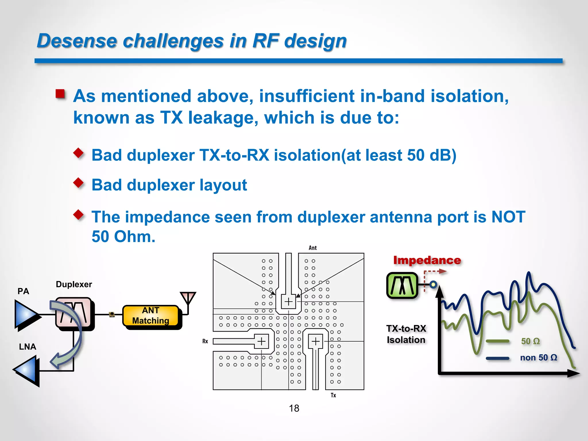
![Desense challenges in RF design
For CA case, multiband RF radio signals can interfere
with each other because of[1]:
Insufficient in-band isolation
Insufficient cross-band isolation
Both of insufficient in-band and cross-band isolation
17](https://image.slidesharecdn.com/abcsofcarrieraggregation-180420073403/75/ABCs-of-Carrier-Aggregation-17-2048.jpg)
![Desense challenges in RF design
As mentioned above, insufficient cross-band isolation
is due to[1]:
Poor isolation between antennas
Poor isolation between PCB layout traces
Poor isolation between ASM(Antenna Switch Module) ports
19](https://image.slidesharecdn.com/abcsofcarrieraggregation-180420073403/75/ABCs-of-Carrier-Aggregation-19-2048.jpg)
![Desense challenges in RF design
As mentioned above, for (B17/B4) combination CA case,
B17 third harmonics may interfere B4 received signal
due to poor isolation between antennas, as shown
below[1]:
20](https://image.slidesharecdn.com/abcsofcarrieraggregation-180420073403/75/ABCs-of-Carrier-Aggregation-20-2048.jpg)
![Desense challenges in RF design
As mentioned above, for (B17/B4) combination CA case,
B17 third harmonics may interfere B4 received signal
due to poor isolation between the two ANT port
traces[1].
B17 3fo
Couple
21](https://image.slidesharecdn.com/abcsofcarrieraggregation-180420073403/75/ABCs-of-Carrier-Aggregation-21-2048.jpg)
![Desense challenges in RF design
As mentioned above, for (B17/B4) combination CA case,
B17 third harmonics may interfere B4 received signal
due to poor isolation between ASM ports[1].
B4 PRX
B17 3f0
22](https://image.slidesharecdn.com/abcsofcarrieraggregation-180420073403/75/ABCs-of-Carrier-Aggregation-22-2048.jpg)
![Desense challenges in RF design
Thus, for (LB/MB) or (LB/HB) combination of CA, the
LB/MB/HB primary and diversity switches should be
independent to mitigate LB harmonics desense issue[3].
23](https://image.slidesharecdn.com/abcsofcarrieraggregation-180420073403/75/ABCs-of-Carrier-Aggregation-23-2048.jpg)
![Desense challenges in RF design
Conversely, an ASM or DSM comprising all LB/MB/HB
ports is not suitable for (LB/MB) or (LB/HB)
combination of CA[4].
24](https://image.slidesharecdn.com/abcsofcarrieraggregation-180420073403/75/ABCs-of-Carrier-Aggregation-24-2048.jpg)
![Intra-Band Uplink Challenges
Intra‐band uplink CA signals use more bandwidth and
have higher peak‐to‐average power ratios (PAPRs) than
standard LTE signals because more subcarriers lead to
higher PAPRs[1,2].
Also, numerous possible configurations of resource
blocks (RBs) exist in multiple component carriers (CCs)
where signals could mix and create spurious
out‐of‐band problems[1].
25](https://image.slidesharecdn.com/abcsofcarrieraggregation-180420073403/75/ABCs-of-Carrier-Aggregation-25-2048.jpg)
![Intra-Band Uplink Challenges
As an example, two contiguous 20 MHz CCs using all
200 RBs would be allowed to back off the maximum
power by 2dB. For the same two 20MHz CCs with 50
RBs allocated in each CC — positioned so there are 100
adjacent RBs — the transmitter would have 1dB MPR.
This situation occurs because the 100 adjacent RBs
can’t create as many out‐of‐band problems as in
the 200 RB scenario[1].
26](https://image.slidesharecdn.com/abcsofcarrieraggregation-180420073403/75/ABCs-of-Carrier-Aggregation-26-2048.jpg)
![Intra-Band Uplink Challenges
As mentioned above, Intra‐band, uplink CA signals
have higher peaks, more signal bandwidth, and new RB
configurations. High linearity of PA is required even
though MPR is implemented[1].
ACLR, intermodulation products of non‐contiguous
RBs, spurious emissions, noise, and sensitivity must
be considered[1].
For example, a PA transmitting two 20 MHz CCs with 2
dB back‐off requires more linearity than a 20 MHz 100
RB FDD waveform at 1 dB back‐off to achieve the same
ACLR, even without considering memory effects related
to the wider bandwidth[1].27](https://image.slidesharecdn.com/abcsofcarrieraggregation-180420073403/75/ABCs-of-Carrier-Aggregation-27-2048.jpg)
![Recognizing Inter‐Band Uplink Challenges
Inter‐band uplink CA combines transmit signals from
different bands. The maximum total power transmitted
from a mobile device is NOT increased in these cases,
so for two transmit bands, each band carries half the
power of a normal transmission, or 3 dB less than a
non‐CA signal[1].
Unlike Intra-Band UL CA, because CCs are in different
bands, there will not be high PAPRs issue. And the
transmit power is reduced for each, the PA linearity isn’t
an issue[1].
28](https://image.slidesharecdn.com/abcsofcarrieraggregation-180420073403/75/ABCs-of-Carrier-Aggregation-28-2048.jpg)
![Recognizing Inter‐Band Uplink Challenges
Nevertheless, other front‐end components, like
switches, have to deal with high‐level signals from
different bands that can mix and create intermodulation
products, which can interfere with one of the active
cellular receivers. Thus, to manage these signals,
switches must have very high linearity[1].
PA
Transceiver
B1/B3
B1
B3
IMD3
B1 DRX Path
Pri ANT
Div ANT
IMD3 = 2*B1TX-B3TX = B1RX
29](https://image.slidesharecdn.com/abcsofcarrieraggregation-180420073403/75/ABCs-of-Carrier-Aggregation-29-2048.jpg)
![Reference
[1] Carrier Aggregation Fundamentals For Dummies, Qorvo
[2] LTE Carrier Aggregation Technology Development and Deployment Worldwide
[3] SDR660 + QLN10xx + QLN2042 + Qualcomm® RF360™ with QPA5460, QPA88xx, and QPA4340
Global ET Configuration Design Example Schematic, Qualcomm
[4] SKY77916-21 Tx-Rx Front-End Module for Quad-Band GSM / GPRS / EDGE w/ 14 Linear TRx
Switch Ports, Dual-Band TD-SCDMA, and TDD LTE Band 39, SKYWORKS
30](https://image.slidesharecdn.com/abcsofcarrieraggregation-180420073403/75/ABCs-of-Carrier-Aggregation-30-2048.jpg)

Carrier aggregation (CA) is a technique that combines multiple LTE component carriers to support wider bandwidth signals, increase data rates, and improve network performance. Mobile carriers can use CA to boost speeds and capacity by aggregating spectrum from low, mid, and high frequency bands. CA allows downlink data rates to evolve to higher levels. Key challenges for implementing CA include ensuring sufficient downlink sensitivity, preventing harmonic generation interference, and providing adequate isolation between carrier components to avoid desense issues.