Download as PDF, PPTX

![Linearity Requirement on 802.11ac Transmitter/PA
n 802.11AC VS. 802.11N
u In order to ensure modulation quality, 256-QAM (802.11ac)
requires more stringent EVM requirement than 64-QAM
(802.11n) due to higher constellation density [1]](https://image.slidesharecdn.com/challengesindesigning5ghz802-160726135437/75/Challenges-In-Designing-5-GHz-802-11-ac-WIFI-Power-Amplifiers-4-2048.jpg)
![Linearity Requirement on 802.11ac Transmitter/PA
n 802.11AC VS. 802.11N
[8]](https://image.slidesharecdn.com/challengesindesigning5ghz802-160726135437/75/Challenges-In-Designing-5-GHz-802-11-ac-WIFI-Power-Amplifiers-5-2048.jpg)
![Linearity Requirement on 802.11ac Transmitter/PA
n 802.11AC VS. 802.11N
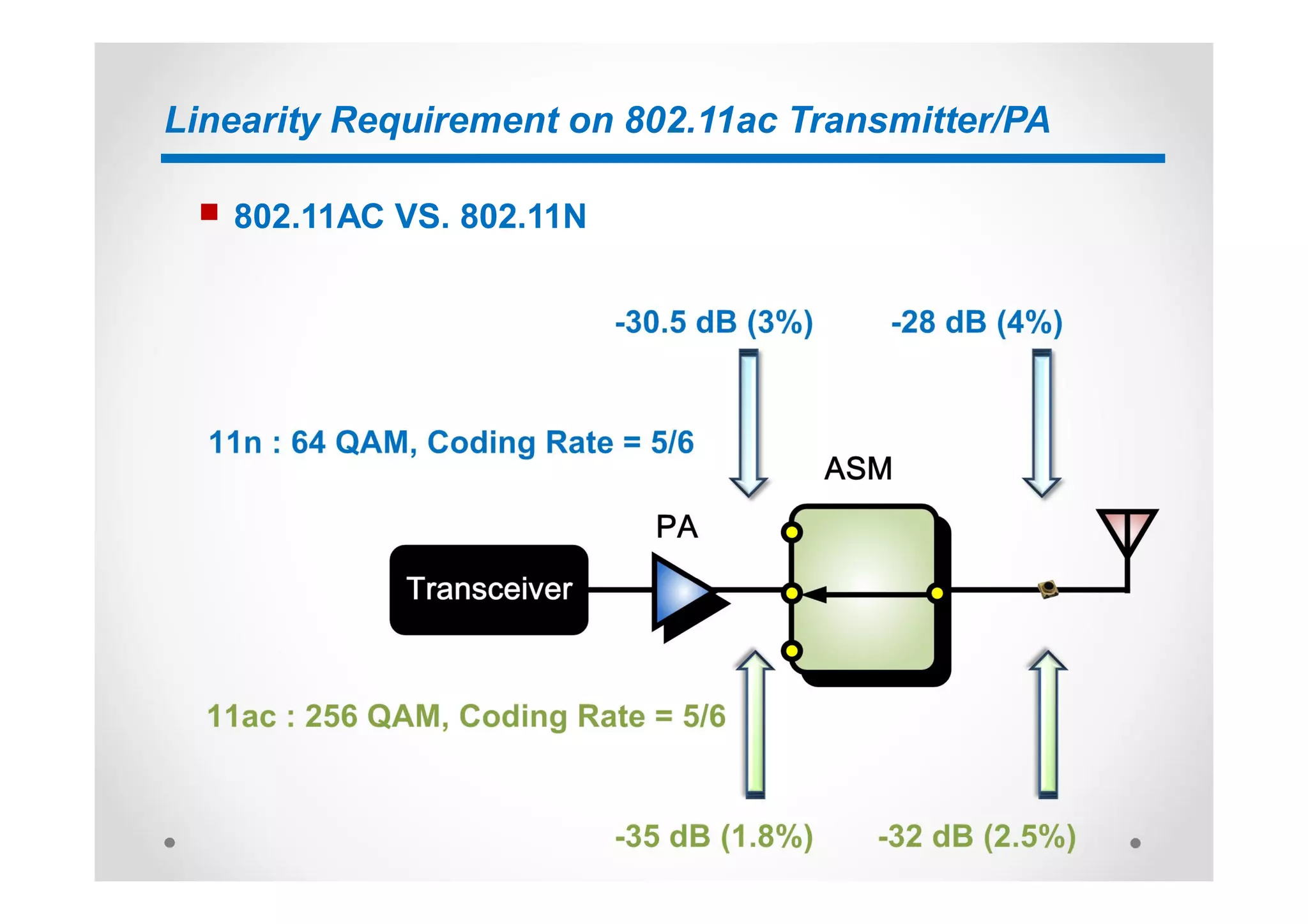
u In 802.11n, the maximum allowed EVM of the WiFi
transmitter is -28dB or 4%, when using 64 QAM with a
coding rate of 5/6. In order to meet this requirement over
varying temperatures and power supply voltage levels, the
WiFi PA or FEM is typically required to achieve an EVM
below -30.5dB or 3%.
u In 802.11ac, the maximum allowed EVM of the WiFi
transmitter has been reduced to -32dB or 2.5% while the
WiFi PA usually needs to achieve an EVM below -35dB
or 1.8%, when being tested with an 80MHz 11ac MCS9
signal (i.e., 256-QAM modulation with a coding rate of
5/6) [1].](https://image.slidesharecdn.com/challengesindesigning5ghz802-160726135437/75/Challenges-In-Designing-5-GHz-802-11-ac-WIFI-Power-Amplifiers-6-2048.jpg)
![Linearity Requirement on 802.11ac Transmitter/PA
n 802.11AC VS. 802.11N
u Take RFMD RFFM8505 802.11ac Front End Module (FEM) for
example, it achieves 19dBm power @ 1.8% EVM spec
in TX Mode [1]](https://image.slidesharecdn.com/challengesindesigning5ghz802-160726135437/75/Challenges-In-Designing-5-GHz-802-11-ac-WIFI-Power-Amplifiers-8-2048.jpg)
![Linearity Requirement on 802.11ac Transmitter/PA
n 802.11AC VS. 802.11N
u 11n PA meets 17.5 dBm output power @ 3% EVM, but can
only meet 10dBm output power @ 1.8% EVM
(11ac requirement) [1]
u 11n PA needs re-optimization to meet 11ac EVM at same
output power
u In other words, in terms of EVM, 11ac is the worst case. If
the test result can meet 11ac requirement, it should be able
to meet 11n requirement as well.](https://image.slidesharecdn.com/challengesindesigning5ghz802-160726135437/75/Challenges-In-Designing-5-GHz-802-11-ac-WIFI-Power-Amplifiers-9-2048.jpg)
![Design Challenge 1: Very Low EVM Requirement
n Usually 802.11ac PAs need to achieve better than -35dB
or 1.8% EVM [1]
n Very stringent requirements for PA AM/AM and AM/PM
distortion:
0.3dB Gain Imbalance or 2 Phase Imbalance can cause
1.8% EVM](https://image.slidesharecdn.com/challengesindesigning5ghz802-160726135437/75/Challenges-In-Designing-5-GHz-802-11-ac-WIFI-Power-Amplifiers-10-2048.jpg)
![Design Challenge 1: Very Low EVM Requirement
n Due to very low EVM requirement, the transmitter
adopting Direct Up-conversion architecture need more
careful design. Otherwise, the EVM performance is still
bad even though the PA has good EVM performance [9]](https://image.slidesharecdn.com/challengesindesigning5ghz802-160726135437/75/Challenges-In-Designing-5-GHz-802-11-ac-WIFI-Power-Amplifiers-11-2048.jpg)
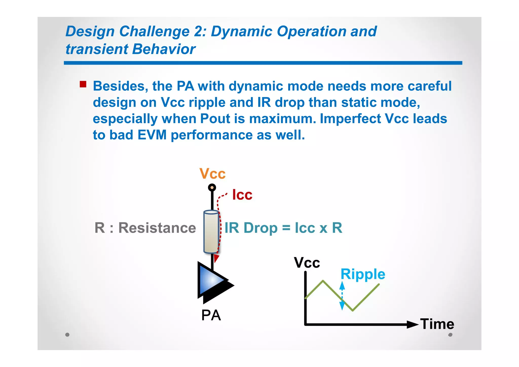
![Design Challenge 2: Dynamic Operation and
transient Behavior
n WiFi networks utilize Time Division Duplexing (TDD) –
PA is pulsed on and off during usage (dynamic
operation)
n Dynamic mode has worse linearity performance than
static mode, so dynamic operation needs careful
design of PA transient/thermal behavior [1]](https://image.slidesharecdn.com/challengesindesigning5ghz802-160726135437/75/Challenges-In-Designing-5-GHz-802-11-ac-WIFI-Power-Amplifiers-12-2048.jpg)
![Design Challenge 2: Dynamic Operation and
transient Behavior
n Once PA is on, amplitude must be flat during entire
transmission. Otherwise, any rise or droop contributes
to AM/AM distortion and degrades EVM [1]](https://image.slidesharecdn.com/challengesindesigning5ghz802-160726135437/75/Challenges-In-Designing-5-GHz-802-11-ac-WIFI-Power-Amplifiers-13-2048.jpg)
![Design Challenge 3: Achieve PAE and Linearity
Simultaneously
n Simple way to improve linearity (EVM) is to increase Icc;
however, not acceptable to customers because of lower
PAE [1]
n Need to achieve PAE & linearity simultaneously:
optimize load, interstage match, bias circuits [1]](https://image.slidesharecdn.com/challengesindesigning5ghz802-160726135437/75/Challenges-In-Designing-5-GHz-802-11-ac-WIFI-Power-Amplifiers-15-2048.jpg)
![Design Challenge 4: Wide Operation Bandwidth
n Wider channel bandwidth of 802.11ac (80/160 MHz):
bias circuit must have sufficient bandwidth to avoid
clipping signal and resulting in distortion [1]
n Very flat gain and very little phase distortion channel to
avoid EVM degradation](https://image.slidesharecdn.com/challengesindesigning5ghz802-160726135437/75/Challenges-In-Designing-5-GHz-802-11-ac-WIFI-Power-Amplifiers-16-2048.jpg)
![Design Challenge 4: Wide Operation Bandwidth
n Take RFMD RFFM8505 802.11ac FEM for example, FEM
achieves ~29 dB Gain at various 802.11ac channels,
and gain is very flat up to 19 dBm output power, to
avoid EVM degradation [1]](https://image.slidesharecdn.com/challengesindesigning5ghz802-160726135437/75/Challenges-In-Designing-5-GHz-802-11-ac-WIFI-Power-Amplifiers-17-2048.jpg)
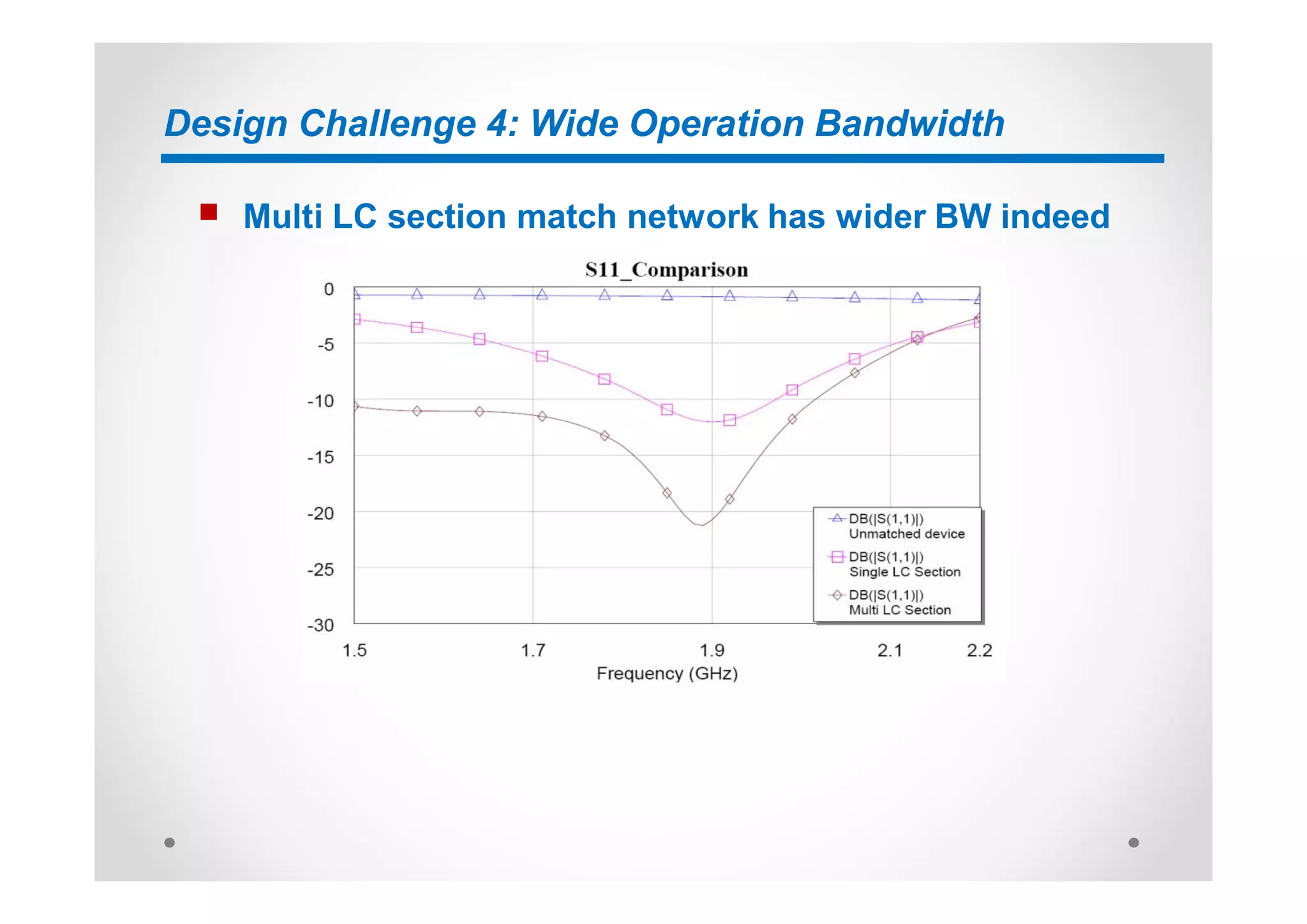
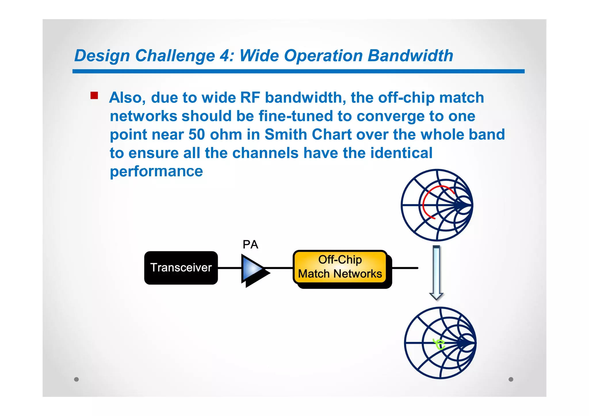
![Design Challenge 4: Wide Operation Bandwidth
n RF bandwidth from 5170 to 5835 MHz (~15% fractional
BW), it indicates that PA’s on-die match network
should adopt multi LC section to achieve enough BW
[1]](https://image.slidesharecdn.com/challengesindesigning5ghz802-160726135437/75/Challenges-In-Designing-5-GHz-802-11-ac-WIFI-Power-Amplifiers-18-2048.jpg)
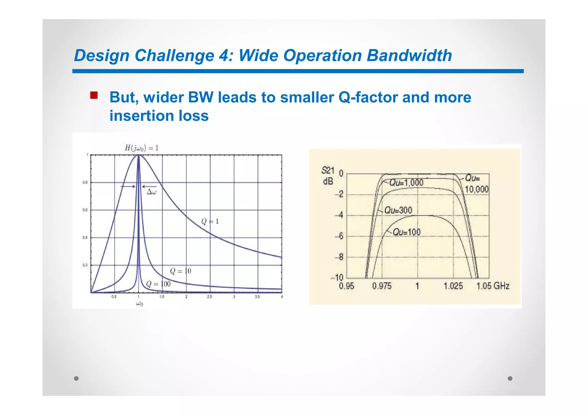
![Design Challenge 4: Wide Operation Bandwidth
n The larger the PA output power is , the worse linearity
and more current consumption will be [10]](https://image.slidesharecdn.com/challengesindesigning5ghz802-160726135437/75/Challenges-In-Designing-5-GHz-802-11-ac-WIFI-Power-Amplifiers-22-2048.jpg)
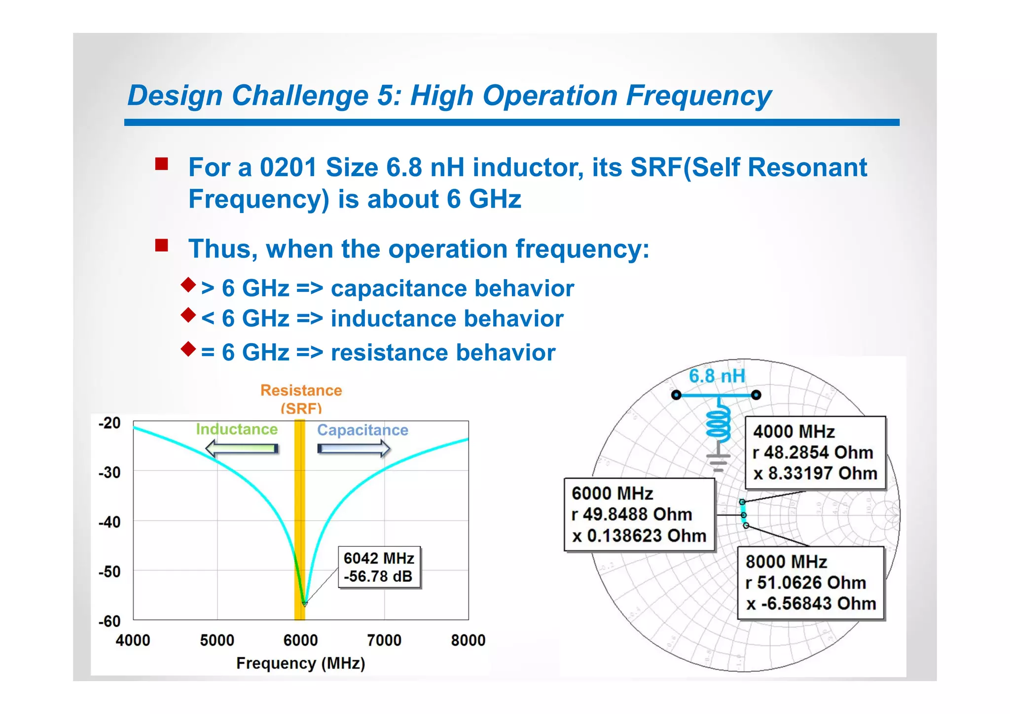
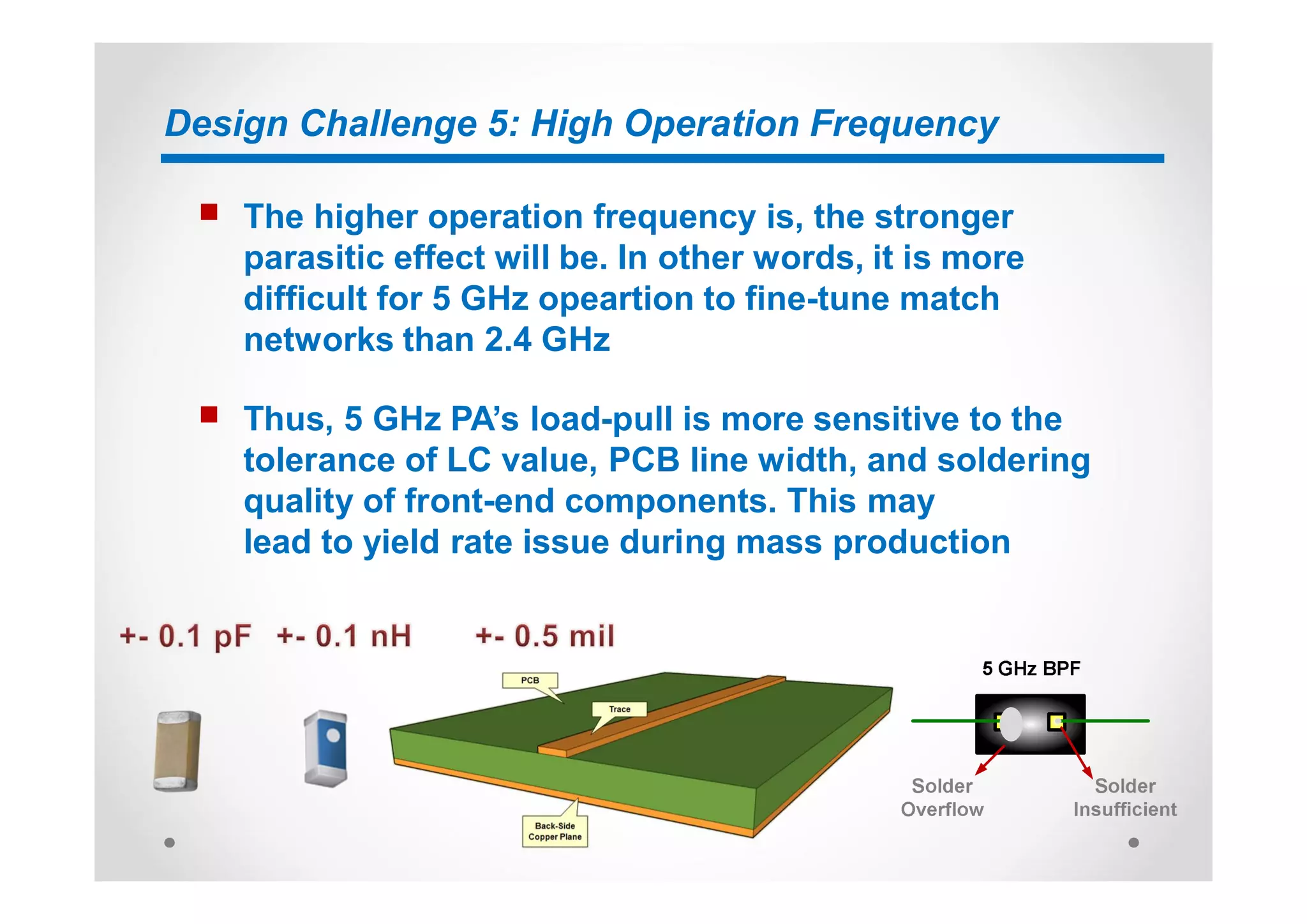
![Design Challenge 5: High Operation Frequency
n In general, due to skin effect, the higher frequency is,
the more insertion loss(IL) will be. Take the
WiFi 2.4 GHz / 5 GHz diplexer for example [11] :](https://image.slidesharecdn.com/challengesindesigning5ghz802-160726135437/75/Challenges-In-Designing-5-GHz-802-11-ac-WIFI-Power-Amplifiers-24-2048.jpg)
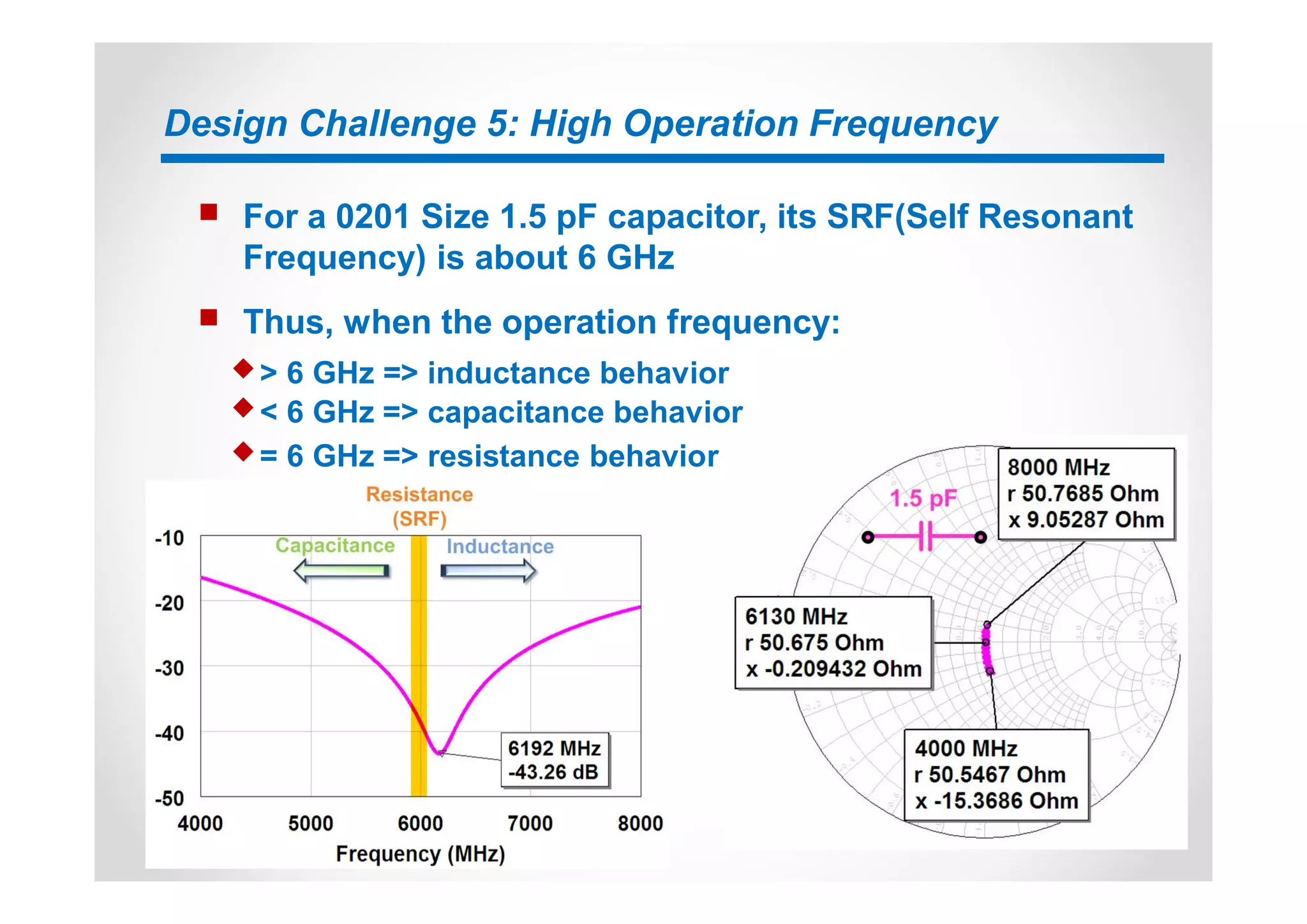
![Design Challenge 5: High Operation Frequency
n In 2.4 GHz, the IL is less than 0.5 dB. Nevertheless, in
5 GHz, the IL is more than 0.5 dB [11] :
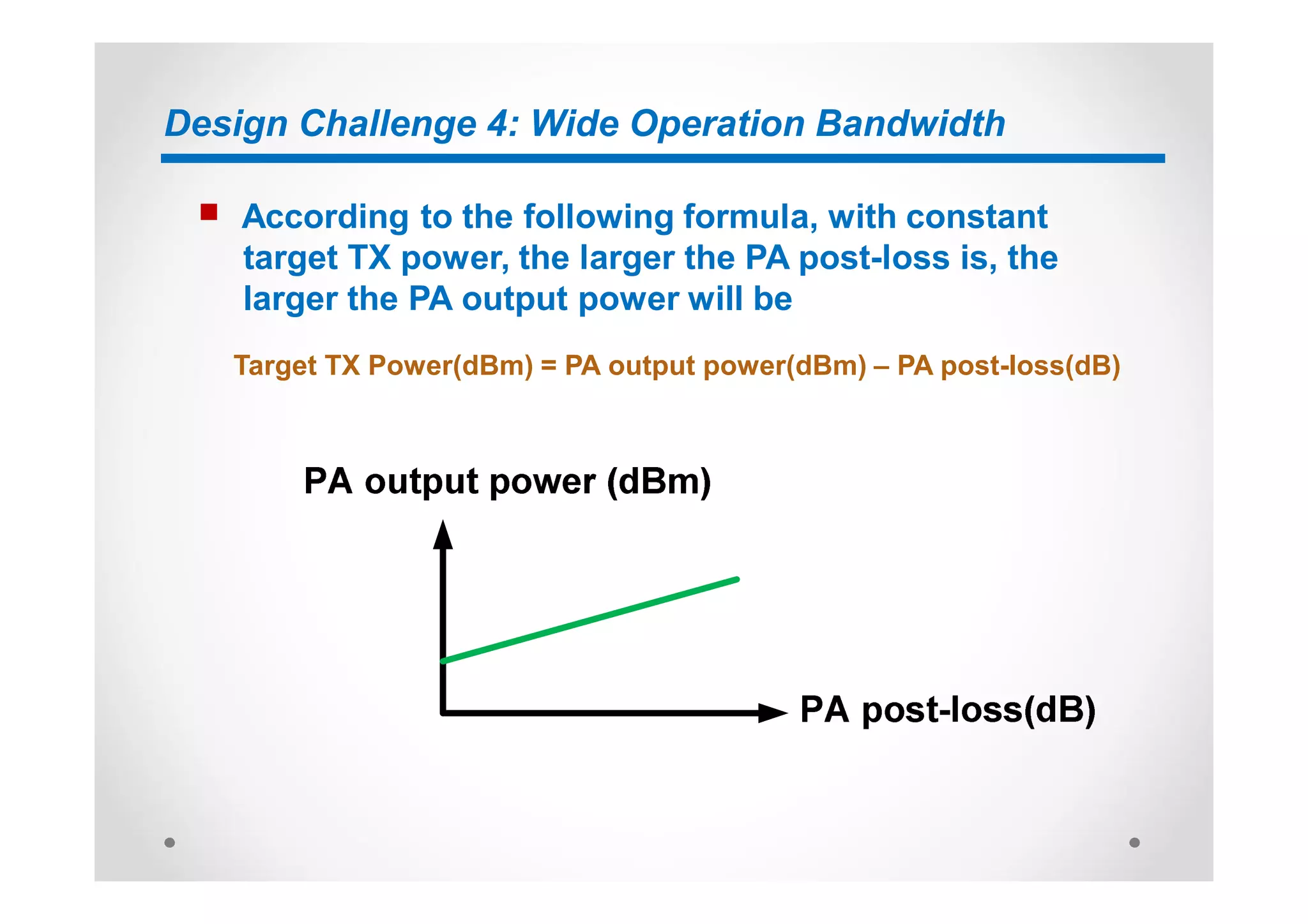
n As mentioned above, with constant target TX power,
the larger the PA post-loss is, the larger the PA output
power and worse linearity will be](https://image.slidesharecdn.com/challengesindesigning5ghz802-160726135437/75/Challenges-In-Designing-5-GHz-802-11-ac-WIFI-Power-Amplifiers-25-2048.jpg)
![Reference
[1] CHALLENGES IN DESIGNING 5 GHZ 802.11AC WIFI POWER AMPLIFIERS, RFMD
[2] WCN3660 EVM Degradation Issue Technical Note, Qualcomm
[3] SE5516A: Dual-Band 802.11a/b/g/n/ac WLAN Front-End Module, SKYWORKS
[4] 802.11ac Technology Introduction White Paper, RHODE & SCHWARZ
[5] WLAN IEEE 802.11ac Wide bandwidth high speed 802.11ac technology and testing,
RHODE & SCHWARZ
[6] ACPF-7024 ISM Bandpass Filter (2401 – 2482 MHz), AVAGO
[7] WCN36x0(A) RF Matching Guidelines, Qualcomm
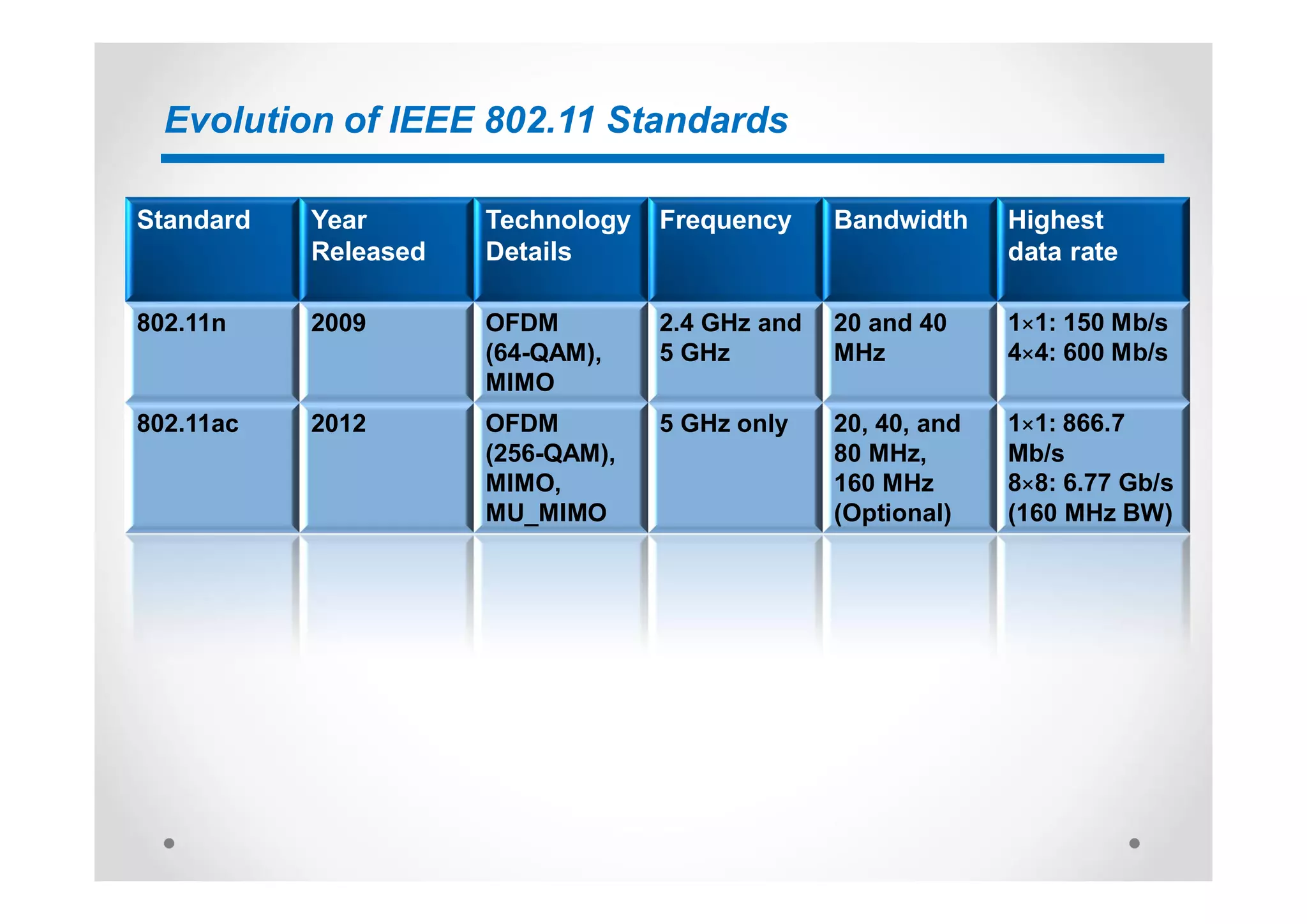
[8] MCS Index for 802.11n and 802.11ac Chart
[9] Sources of Error in IQ Based RF Signal Generation
[10] Integration Aids 802.11ac Mobile Wi-Fi Front Ends
[11] Mini filters for multiband devices, TDK](https://image.slidesharecdn.com/challengesindesigning5ghz802-160726135437/75/Challenges-In-Designing-5-GHz-802-11-ac-WIFI-Power-Amplifiers-31-2048.jpg)

Designing 5 GHz 802.11ac WiFi power amplifiers presents several challenges: (1) meeting the stringent error vector magnitude (EVM) requirement of less than 1.8% due to higher order modulations, (2) ensuring stable performance during dynamic on/off operation while avoiding transients that degrade EVM, and (3) optimizing the power amplifier to achieve both high power-added efficiency and linearity over wide 80/160 MHz bandwidths at 5 GHz frequencies. Addressing these challenges requires careful design of the power amplifier, bias circuits, and matching networks.
This presentation outlines challenges in designing 5 GHz 802.11ac WiFi PAs, including stringent EVM requirements, dynamic operation, achieving PAE and linearity, wide operation bandwidth, and high operation frequency.