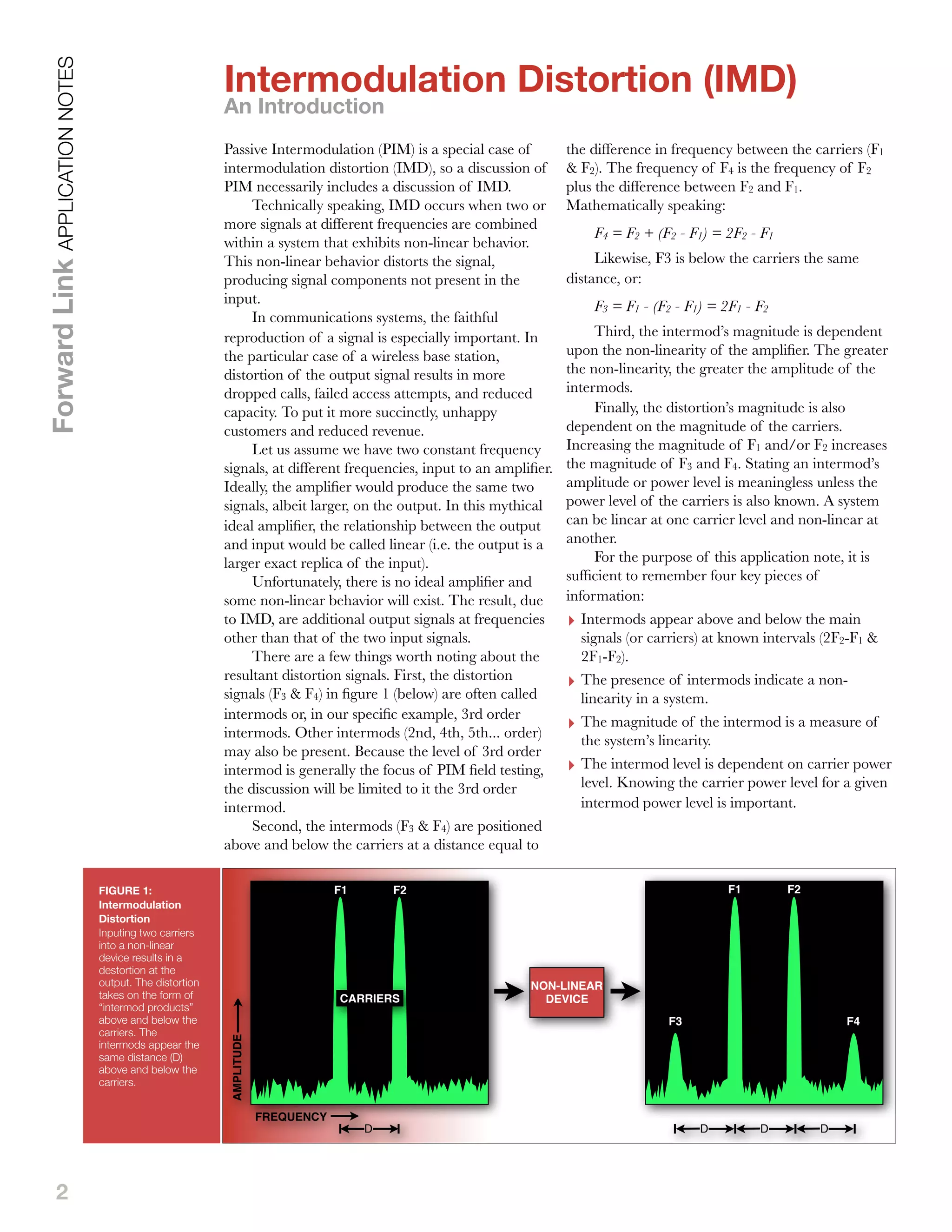
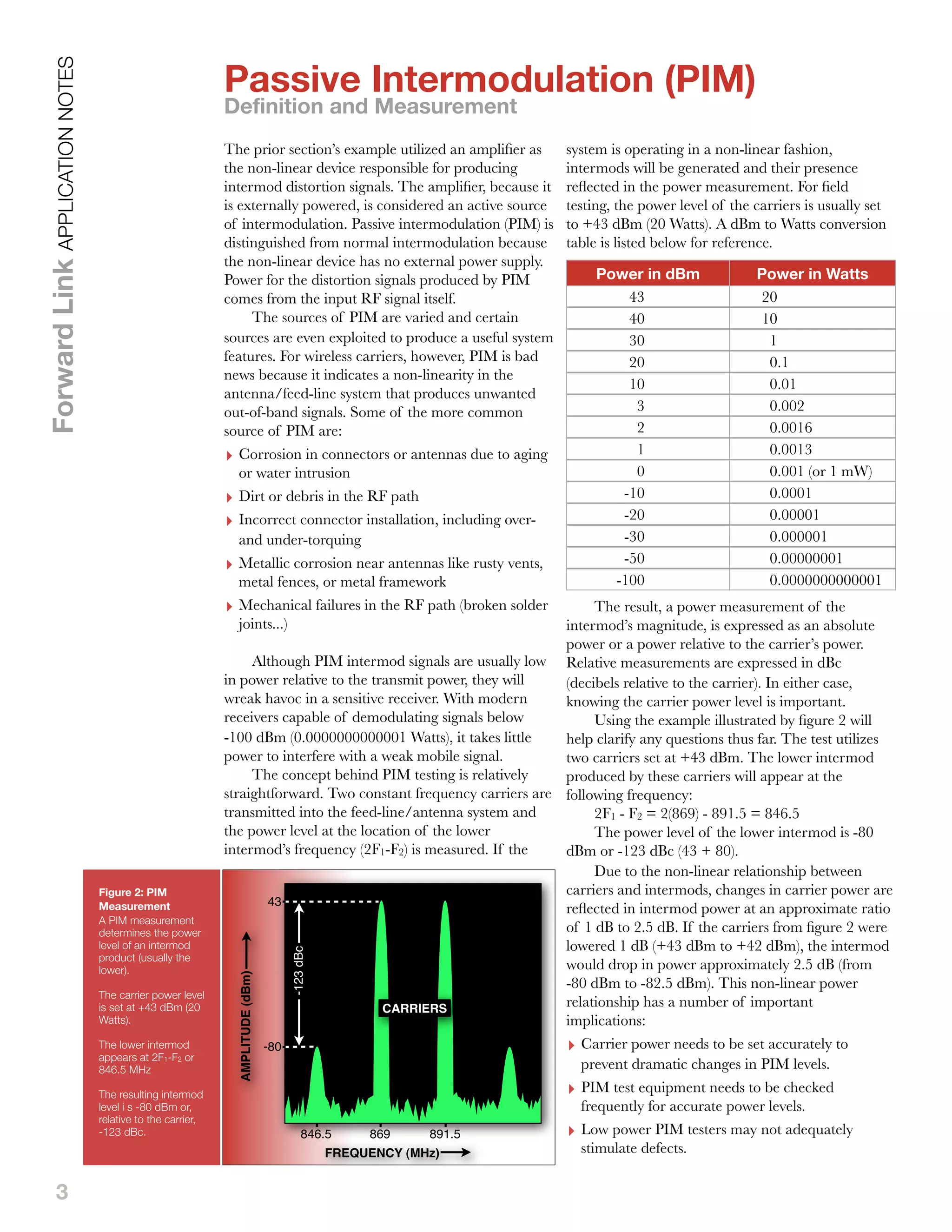
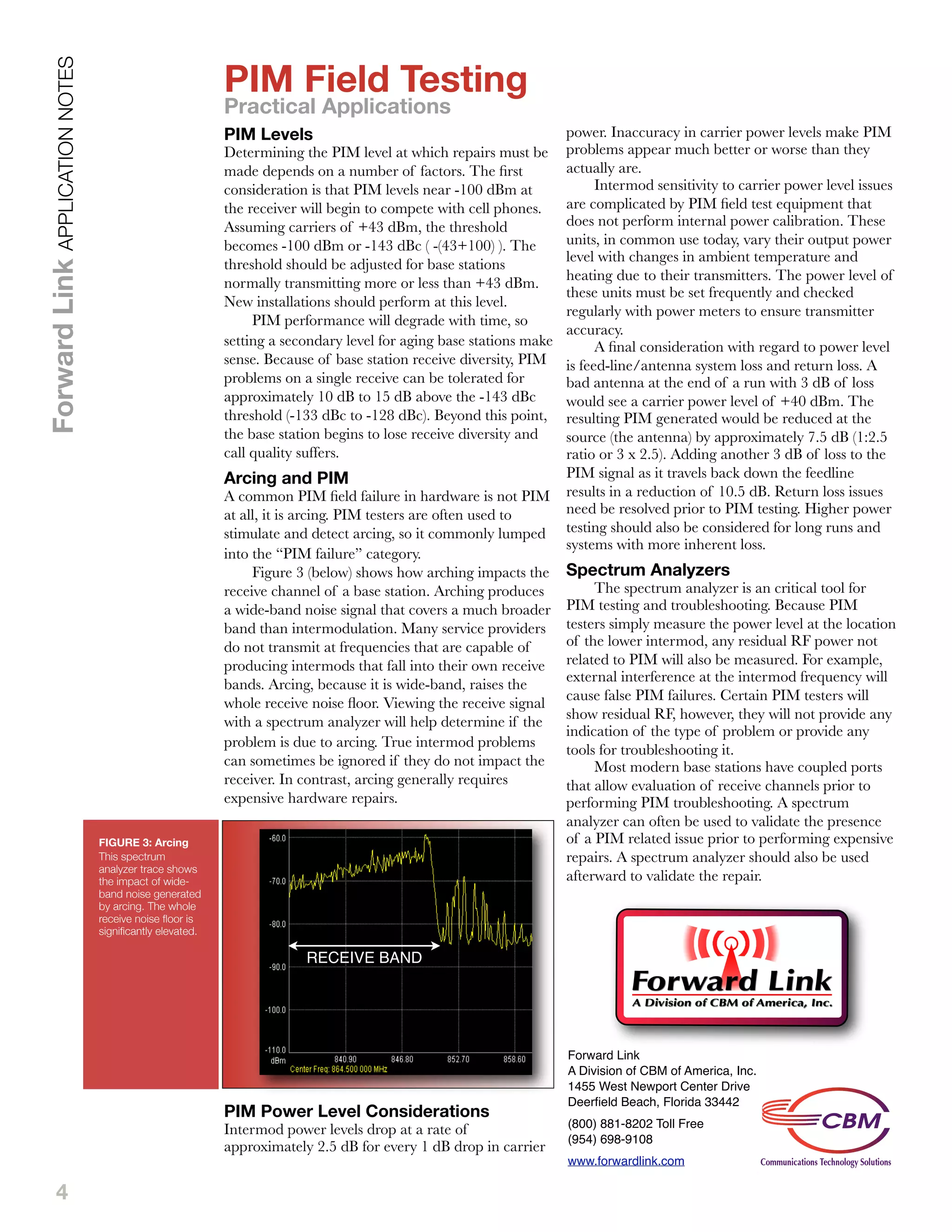
1
Overview
Passive intermodulation (PIM) has
become a hot topic within wireless
carriers. While the PIM
phenomenon has been known and
studied for many decades, wireless
carriers have traditionally limited
their PIM testing to labs. The
more recent introduction of
portable test equipment targeted
at resolving PIM issues in the field
has extended the topic to a much
broader audience, including
thousands of field operations
personnel tasked with maintaining
wireless networks.
There are many practical
reasons, beyond equipment
availability, for an increased
interest in PIM and PIM field
testing. PIM problems tend to
increase as RF transmission
hardware ages. Temperature
cycling, corrosion, and vibration
all negatively impact PIM
performance. Carrier networks
are aging and the ability to find
PIM problems related to this
aging is important.
Installation, hardware quality,
and hardware design also play an
important role in determining
PIM performance. The continual
roll-out of of new technologies,
and new hardware, into wireless
networks makes PIM testing in
the field a perfect candidate for
ensuring a high quality of service.
Finally, PIM problems
increase as power increases. The
increase in popularity of mobile
devices requires wireless service
providers to use additional power
to serve their increasing user base.
This application note endeavors
to provide the reader with the
fundamentals necessary to
understand the causes of PIM
and testing necessary to resolve
PIM issues in the field. Technical
complexities not fundamental to a
basic understanding have been
avoided in favor of a more
practical approach. Readers who
desire a more technical treatment
of the topic should download the
Forward Link Understanding PIM
2.0 application note.
Welcome to the first in
our series of
application notes
addressing Passive
Intermodulation (PIM).
This Forward Link
Application Note
addresses the
Fundamentals of PIM
and PIM testing.
Understanding PIM
2.0 goes beyond the
basics, introducing the
reader to some of the
technical concepts
behind PIM.
Finally, PIM Testing
Fundamentals
addresses the
practical application of
PIM testing in the field.
UNDERSTANDING PIM 1.0
ForwardLinkAPPLICATIONNOTES
2
Passive Intermodulation (PIM) is a special case of
intermodulation distortion (IMD), so a discussion of
PIM necessarily includes a discussion of IMD.
Technically speaking, IMD occurs when two or
more signals at different frequencies are combined
within a system that exhibits non-linear behavior.
This non-linear behavior distorts the signal,
producing signal components not present in the
input.
In communications systems, the faithful
reproduction of a signal is especially important. In
the particular case of a wireless base station,
distortion of the output signal results in more
dropped calls, failed access attempts, and reduced
capacity. To put it more succinctly, unhappy
customers and reduced revenue.
Let us assume we have two constant frequency
signals, at different frequencies, input to an amplifier.
Ideally, the amplifier would produce the same two
signals, albeit larger, on the output. In this mythical
ideal amplifier, the relationship between the output
and input would be called linear (i.e. the output is a
larger exact replica of the input).
Unfortunately, there is no ideal amplifier and
some non-linear behavior will exist. The result, due
to IMD, are additional output signals at frequencies
other than that of the two input signals.
There are a few things worth noting about the
resultant distortion signals. First, the distortion
signals (F3 & F4) in figure 1 (below) are often called
intermods or, in our specific example, 3rd order
intermods. Other intermods (2nd, 4th, 5th... order)
may also be present. Because the level of 3rd order
intermod is generally the focus of PIM field testing,
the discussion will be limited to it the 3rd order
intermod.
Second, the intermods (F3 & F4) are positioned
above and below the carriers at a distance equal to
the difference in frequency between the carriers (F1
& F2). The frequency of F4 is the frequency of F2
plus the difference between F2 and F1.
Mathematically speaking:
F4 = F2 + (F2 - F1) = 2F2 - F1
Likewise, F3 is below the carriers the same
distance, or:
F3 = F1 - (F2 - F1) = 2F1 - F2
Third, the intermod’s magnitude is dependent
upon the non-linearity of the amplifier. The greater
the non-linearity, the greater the amplitude of the
intermods.
Finally, the distortion’s magnitude is also
dependent on the magnitude of the carriers.
Increasing the magnitude of F1 and/or F2 increases
the magnitude of F3 and F4. Stating an intermod’s
amplitude or power level is meaningless unless the
power level of the carriers is also known. A system
can be linear at one carrier level and non-linear at
another.
For the purpose of this application note, it is
sufficient to remember four key pieces of
information:
‣ Intermods appear above and below the main
signals (or carriers) at known intervals (2F2-F1 &
2F1-F2).
‣ The presence of intermods indicate a non-
linearity in a system.
‣ The magnitude of the intermod is a measure of
the system’s linearity.
‣ The intermod level is dependent on carrier power
level. Knowing the carrier power level for a given
intermod power level is important.
Intermodulation Distortion (IMD)
An Introduction
ForwardLinkAPPLICATIONNOTES
FIGURE 1:
Intermodulation
Distortion
Inputing two carriers
into a non-linear
device results in a
destortion at the
output. The distortion
takes on the form of
“intermod products”
above and below the
carriers. The
intermods appear the
same distance (D)
above and below the
carriers.
F1 F2
F3 F4
F1 F2
CARRIERS
NON-LINEAR
DEVICE
D D D D
AMPLITUDE
FREQUENCY
3
The prior section’s example utilized an amplifier as
the non-linear device responsible for producing
intermod distortion signals. The amplifier, because it
is externally powered, is considered an active source
of intermodulation. Passive intermodulation (PIM) is
distinguished from normal intermodulation because
the non-linear device has no external power supply.
Power for the distortion signals produced by PIM
comes from the input RF signal itself.
The sources of PIM are varied and certain
sources are even exploited to produce a useful system
features. For wireless carriers, however, PIM is bad
news because it indicates a non-linearity in the
antenna/feed-line system that produces unwanted
out-of-band signals. Some of the more common
source of PIM are:
‣ Corrosion in connectors or antennas due to aging
or water intrusion
‣ Dirt or debris in the RF path
‣ Incorrect connector installation, including over-
and under-torquing
‣ Metallic corrosion near antennas like rusty vents,
metal fences, or metal framework
‣ Mechanical failures in the RF path (broken solder
joints...)
Although PIM intermod signals are usually low
in power relative to the transmit power, they will
wreak havoc in a sensitive receiver. With modern
receivers capable of demodulating signals below
-100 dBm (0.0000000000001 Watts), it takes little
power to interfere with a weak mobile signal.
The concept behind PIM testing is relatively
straightforward. Two constant frequency carriers are
transmitted into the feed-line/antenna system and
the power level at the location of the lower
intermod’s frequency (2F1-F2) is measured. If the
system is operating in a non-linear fashion,
intermods will be generated and their presence
reflected in the power measurement. For field
testing, the power level of the carriers is usually set
to +43 dBm (20 Watts). A dBm to Watts conversion
table is listed below for reference.
Power in dBm Power in Watts
	 43 	 20
	 40 	 10
	 30 	 1
	 20 	 0.1
	 10 	 0.01
	 3 	 0.002
	 2 	 0.0016
	 1 	 0.0013
	 0 	 0.001 (or 1 mW)
	 -10 	 0.0001
	 -20 	 0.00001
	 -30 	 0.000001
	 -50 	 0.00000001
	 -100 	 0.0000000000001
The result, a power measurement of the
intermod’s magnitude, is expressed as an absolute
power or a power relative to the carrier’s power.
Relative measurements are expressed in dBc
(decibels relative to the carrier). In either case,
knowing the carrier power level is important.
Using the example illustrated by figure 2 will
help clarify any questions thus far. The test utilizes
two carriers set at +43 dBm. The lower intermod
produced by these carriers will appear at the
following frequency:
2F1 - F2 = 2(869) - 891.5 = 846.5
The power level of the lower intermod is -80
dBm or -123 dBc (43 + 80).
Due to the non-linear relationship between
carriers and intermods, changes in carrier power are
reflected in intermod power at an approximate ratio
of 1 dB to 2.5 dB. If the carriers from figure 2 were
lowered 1 dB (+43 dBm to +42 dBm), the intermod
would drop in power approximately 2.5 dB (from
-80 dBm to -82.5 dBm). This non-linear power
relationship has a number of important
implications:
‣ Carrier power needs to be set accurately to
prevent dramatic changes in PIM levels.
‣ PIM test equipment needs to be checked
frequently for accurate power levels.
‣ Low power PIM testers may not adequately
stimulate defects.
Passive Intermodulation (PIM)
Definition and Measurement
ForwardLinkAPPLICATIONNOTES
Figure 2: PIM
Measurement
A PIM measurement
determines the power
level of an intermod
product (usually the
lower).
The carrier power level
is set at +43 dBm (20
Watts).
The lower intermod
appears at 2F1-F2 or
846.5 MHz
The resulting intermod
level i s -80 dBm or,
relative to the carrier,
-123 dBc.
CARRIERS
AMPLITUDE(dBm)
FREQUENCY (MHz)
-80
43
-123dBc
846.5 869 891.5
4
PIM Levels
Determining the PIM level at which repairs must be
made depends on a number of factors. The first
consideration is that PIM levels near -100 dBm at
the receiver will begin to compete with cell phones.
Assuming carriers of +43 dBm, the threshold
becomes -100 dBm or -143 dBc ( -(43+100) ). The
threshold should be adjusted for base stations
normally transmitting more or less than +43 dBm.
New installations should perform at this level.
PIM performance will degrade with time, so
setting a secondary level for aging base stations make
sense. Because of base station receive diversity, PIM
problems on a single receive can be tolerated for
approximately 10 dB to 15 dB above the -143 dBc
threshold (-133 dBc to -128 dBc). Beyond this point,
the base station begins to lose receive diversity and
call quality suffers.
Arcing and PIM
A common PIM field failure in hardware is not PIM
at all, it is arcing. PIM testers are often used to
stimulate and detect arcing, so it commonly lumped
into the “PIM failure” category.
Figure 3 (below) shows how arching impacts the
receive channel of a base station. Arching produces
a wide-band noise signal that covers a much broader
band than intermodulation. Many service providers
do not transmit at frequencies that are capable of
producing intermods that fall into their own receive
bands. Arcing, because it is wide-band, raises the
whole receive noise floor. Viewing the receive signal
with a spectrum analyzer will help determine if the
problem is due to arcing. True intermod problems
can sometimes be ignored if they do not impact the
receiver. In contrast, arcing generally requires
expensive hardware repairs.
PIM Power Level Considerations
Intermod power levels drop at a rate of
approximately 2.5 dB for every 1 dB drop in carrier
power. Inaccuracy in carrier power levels make PIM
problems appear much better or worse than they
actually are.
Intermod sensitivity to carrier power level issues
are complicated by PIM field test equipment that
does not perform internal power calibration. These
units, in common use today, vary their output power
level with changes in ambient temperature and
heating due to their transmitters. The power level of
these units must be set frequently and checked
regularly with power meters to ensure transmitter
accuracy.
A final consideration with regard to power level
is feed-line/antenna system loss and return loss. A
bad antenna at the end of a run with 3 dB of loss
would see a carrier power level of +40 dBm. The
resulting PIM generated would be reduced at the
source (the antenna) by approximately 7.5 dB (1:2.5
ratio or 3 x 2.5). Adding another 3 dB of loss to the
PIM signal as it travels back down the feedline
results in a reduction of 10.5 dB. Return loss issues
need be resolved prior to PIM testing. Higher power
testing should also be considered for long runs and
systems with more inherent loss.
Spectrum Analyzers
The spectrum analyzer is an critical tool for
PIM testing and troubleshooting. Because PIM
testers simply measure the power level at the location
of the lower intermod, any residual RF power not
related to PIM will also be measured. For example,
external interference at the intermod frequency will
cause false PIM failures. Certain PIM testers will
show residual RF, however, they will not provide any
indication of the type of problem or provide any
tools for troubleshooting it.
Most modern base stations have coupled ports
that allow evaluation of receive channels prior to
performing PIM troubleshooting. A spectrum
analyzer can often be used to validate the presence
of a PIM related issue prior to performing expensive
repairs. A spectrum analyzer should also be used
afterward to validate the repair.
PIM Field Testing
Practical Applications
ForwardLinkAPPLICATIONNOTES
FIGURE 3: Arcing
This spectrum
analyzer trace shows
the impact of wide-
band noise generated
by arcing. The whole
receive noise floor is
significantly elevated.
RECEIVE BAND
Forward Link
A Division of CBM of America, Inc.
1455 West Newport Center Drive
Deerfield Beach, Florida 33442
(800) 881-8202 Toll Free
(954) 698-9108
www.forwardlink.com

Understanding pim

  • 1.
    1 Overview Passive intermodulation (PIM)has become a hot topic within wireless carriers. While the PIM phenomenon has been known and studied for many decades, wireless carriers have traditionally limited their PIM testing to labs. The more recent introduction of portable test equipment targeted at resolving PIM issues in the field has extended the topic to a much broader audience, including thousands of field operations personnel tasked with maintaining wireless networks. There are many practical reasons, beyond equipment availability, for an increased interest in PIM and PIM field testing. PIM problems tend to increase as RF transmission hardware ages. Temperature cycling, corrosion, and vibration all negatively impact PIM performance. Carrier networks are aging and the ability to find PIM problems related to this aging is important. Installation, hardware quality, and hardware design also play an important role in determining PIM performance. The continual roll-out of of new technologies, and new hardware, into wireless networks makes PIM testing in the field a perfect candidate for ensuring a high quality of service. Finally, PIM problems increase as power increases. The increase in popularity of mobile devices requires wireless service providers to use additional power to serve their increasing user base. This application note endeavors to provide the reader with the fundamentals necessary to understand the causes of PIM and testing necessary to resolve PIM issues in the field. Technical complexities not fundamental to a basic understanding have been avoided in favor of a more practical approach. Readers who desire a more technical treatment of the topic should download the Forward Link Understanding PIM 2.0 application note. Welcome to the first in our series of application notes addressing Passive Intermodulation (PIM). This Forward Link Application Note addresses the Fundamentals of PIM and PIM testing. Understanding PIM 2.0 goes beyond the basics, introducing the reader to some of the technical concepts behind PIM. Finally, PIM Testing Fundamentals addresses the practical application of PIM testing in the field. UNDERSTANDING PIM 1.0 ForwardLinkAPPLICATIONNOTES
  • 2.
    2 Passive Intermodulation (PIM)is a special case of intermodulation distortion (IMD), so a discussion of PIM necessarily includes a discussion of IMD. Technically speaking, IMD occurs when two or more signals at different frequencies are combined within a system that exhibits non-linear behavior. This non-linear behavior distorts the signal, producing signal components not present in the input. In communications systems, the faithful reproduction of a signal is especially important. In the particular case of a wireless base station, distortion of the output signal results in more dropped calls, failed access attempts, and reduced capacity. To put it more succinctly, unhappy customers and reduced revenue. Let us assume we have two constant frequency signals, at different frequencies, input to an amplifier. Ideally, the amplifier would produce the same two signals, albeit larger, on the output. In this mythical ideal amplifier, the relationship between the output and input would be called linear (i.e. the output is a larger exact replica of the input). Unfortunately, there is no ideal amplifier and some non-linear behavior will exist. The result, due to IMD, are additional output signals at frequencies other than that of the two input signals. There are a few things worth noting about the resultant distortion signals. First, the distortion signals (F3 & F4) in figure 1 (below) are often called intermods or, in our specific example, 3rd order intermods. Other intermods (2nd, 4th, 5th... order) may also be present. Because the level of 3rd order intermod is generally the focus of PIM field testing, the discussion will be limited to it the 3rd order intermod. Second, the intermods (F3 & F4) are positioned above and below the carriers at a distance equal to the difference in frequency between the carriers (F1 & F2). The frequency of F4 is the frequency of F2 plus the difference between F2 and F1. Mathematically speaking: F4 = F2 + (F2 - F1) = 2F2 - F1 Likewise, F3 is below the carriers the same distance, or: F3 = F1 - (F2 - F1) = 2F1 - F2 Third, the intermod’s magnitude is dependent upon the non-linearity of the amplifier. The greater the non-linearity, the greater the amplitude of the intermods. Finally, the distortion’s magnitude is also dependent on the magnitude of the carriers. Increasing the magnitude of F1 and/or F2 increases the magnitude of F3 and F4. Stating an intermod’s amplitude or power level is meaningless unless the power level of the carriers is also known. A system can be linear at one carrier level and non-linear at another. For the purpose of this application note, it is sufficient to remember four key pieces of information: ‣ Intermods appear above and below the main signals (or carriers) at known intervals (2F2-F1 & 2F1-F2). ‣ The presence of intermods indicate a non- linearity in a system. ‣ The magnitude of the intermod is a measure of the system’s linearity. ‣ The intermod level is dependent on carrier power level. Knowing the carrier power level for a given intermod power level is important. Intermodulation Distortion (IMD) An Introduction ForwardLinkAPPLICATIONNOTES FIGURE 1: Intermodulation Distortion Inputing two carriers into a non-linear device results in a destortion at the output. The distortion takes on the form of “intermod products” above and below the carriers. The intermods appear the same distance (D) above and below the carriers. F1 F2 F3 F4 F1 F2 CARRIERS NON-LINEAR DEVICE D D D D AMPLITUDE FREQUENCY
  • 3.
    3 The prior section’sexample utilized an amplifier as the non-linear device responsible for producing intermod distortion signals. The amplifier, because it is externally powered, is considered an active source of intermodulation. Passive intermodulation (PIM) is distinguished from normal intermodulation because the non-linear device has no external power supply. Power for the distortion signals produced by PIM comes from the input RF signal itself. The sources of PIM are varied and certain sources are even exploited to produce a useful system features. For wireless carriers, however, PIM is bad news because it indicates a non-linearity in the antenna/feed-line system that produces unwanted out-of-band signals. Some of the more common source of PIM are: ‣ Corrosion in connectors or antennas due to aging or water intrusion ‣ Dirt or debris in the RF path ‣ Incorrect connector installation, including over- and under-torquing ‣ Metallic corrosion near antennas like rusty vents, metal fences, or metal framework ‣ Mechanical failures in the RF path (broken solder joints...) Although PIM intermod signals are usually low in power relative to the transmit power, they will wreak havoc in a sensitive receiver. With modern receivers capable of demodulating signals below -100 dBm (0.0000000000001 Watts), it takes little power to interfere with a weak mobile signal. The concept behind PIM testing is relatively straightforward. Two constant frequency carriers are transmitted into the feed-line/antenna system and the power level at the location of the lower intermod’s frequency (2F1-F2) is measured. If the system is operating in a non-linear fashion, intermods will be generated and their presence reflected in the power measurement. For field testing, the power level of the carriers is usually set to +43 dBm (20 Watts). A dBm to Watts conversion table is listed below for reference. Power in dBm Power in Watts 43 20 40 10 30 1 20 0.1 10 0.01 3 0.002 2 0.0016 1 0.0013 0 0.001 (or 1 mW) -10 0.0001 -20 0.00001 -30 0.000001 -50 0.00000001 -100 0.0000000000001 The result, a power measurement of the intermod’s magnitude, is expressed as an absolute power or a power relative to the carrier’s power. Relative measurements are expressed in dBc (decibels relative to the carrier). In either case, knowing the carrier power level is important. Using the example illustrated by figure 2 will help clarify any questions thus far. The test utilizes two carriers set at +43 dBm. The lower intermod produced by these carriers will appear at the following frequency: 2F1 - F2 = 2(869) - 891.5 = 846.5 The power level of the lower intermod is -80 dBm or -123 dBc (43 + 80). Due to the non-linear relationship between carriers and intermods, changes in carrier power are reflected in intermod power at an approximate ratio of 1 dB to 2.5 dB. If the carriers from figure 2 were lowered 1 dB (+43 dBm to +42 dBm), the intermod would drop in power approximately 2.5 dB (from -80 dBm to -82.5 dBm). This non-linear power relationship has a number of important implications: ‣ Carrier power needs to be set accurately to prevent dramatic changes in PIM levels. ‣ PIM test equipment needs to be checked frequently for accurate power levels. ‣ Low power PIM testers may not adequately stimulate defects. Passive Intermodulation (PIM) Definition and Measurement ForwardLinkAPPLICATIONNOTES Figure 2: PIM Measurement A PIM measurement determines the power level of an intermod product (usually the lower). The carrier power level is set at +43 dBm (20 Watts). The lower intermod appears at 2F1-F2 or 846.5 MHz The resulting intermod level i s -80 dBm or, relative to the carrier, -123 dBc. CARRIERS AMPLITUDE(dBm) FREQUENCY (MHz) -80 43 -123dBc 846.5 869 891.5
  • 4.
    4 PIM Levels Determining thePIM level at which repairs must be made depends on a number of factors. The first consideration is that PIM levels near -100 dBm at the receiver will begin to compete with cell phones. Assuming carriers of +43 dBm, the threshold becomes -100 dBm or -143 dBc ( -(43+100) ). The threshold should be adjusted for base stations normally transmitting more or less than +43 dBm. New installations should perform at this level. PIM performance will degrade with time, so setting a secondary level for aging base stations make sense. Because of base station receive diversity, PIM problems on a single receive can be tolerated for approximately 10 dB to 15 dB above the -143 dBc threshold (-133 dBc to -128 dBc). Beyond this point, the base station begins to lose receive diversity and call quality suffers. Arcing and PIM A common PIM field failure in hardware is not PIM at all, it is arcing. PIM testers are often used to stimulate and detect arcing, so it commonly lumped into the “PIM failure” category. Figure 3 (below) shows how arching impacts the receive channel of a base station. Arching produces a wide-band noise signal that covers a much broader band than intermodulation. Many service providers do not transmit at frequencies that are capable of producing intermods that fall into their own receive bands. Arcing, because it is wide-band, raises the whole receive noise floor. Viewing the receive signal with a spectrum analyzer will help determine if the problem is due to arcing. True intermod problems can sometimes be ignored if they do not impact the receiver. In contrast, arcing generally requires expensive hardware repairs. PIM Power Level Considerations Intermod power levels drop at a rate of approximately 2.5 dB for every 1 dB drop in carrier power. Inaccuracy in carrier power levels make PIM problems appear much better or worse than they actually are. Intermod sensitivity to carrier power level issues are complicated by PIM field test equipment that does not perform internal power calibration. These units, in common use today, vary their output power level with changes in ambient temperature and heating due to their transmitters. The power level of these units must be set frequently and checked regularly with power meters to ensure transmitter accuracy. A final consideration with regard to power level is feed-line/antenna system loss and return loss. A bad antenna at the end of a run with 3 dB of loss would see a carrier power level of +40 dBm. The resulting PIM generated would be reduced at the source (the antenna) by approximately 7.5 dB (1:2.5 ratio or 3 x 2.5). Adding another 3 dB of loss to the PIM signal as it travels back down the feedline results in a reduction of 10.5 dB. Return loss issues need be resolved prior to PIM testing. Higher power testing should also be considered for long runs and systems with more inherent loss. Spectrum Analyzers The spectrum analyzer is an critical tool for PIM testing and troubleshooting. Because PIM testers simply measure the power level at the location of the lower intermod, any residual RF power not related to PIM will also be measured. For example, external interference at the intermod frequency will cause false PIM failures. Certain PIM testers will show residual RF, however, they will not provide any indication of the type of problem or provide any tools for troubleshooting it. Most modern base stations have coupled ports that allow evaluation of receive channels prior to performing PIM troubleshooting. A spectrum analyzer can often be used to validate the presence of a PIM related issue prior to performing expensive repairs. A spectrum analyzer should also be used afterward to validate the repair. PIM Field Testing Practical Applications ForwardLinkAPPLICATIONNOTES FIGURE 3: Arcing This spectrum analyzer trace shows the impact of wide- band noise generated by arcing. The whole receive noise floor is significantly elevated. RECEIVE BAND Forward Link A Division of CBM of America, Inc. 1455 West Newport Center Drive Deerfield Beach, Florida 33442 (800) 881-8202 Toll Free (954) 698-9108 www.forwardlink.com