Download to read offline
![International Journal of Research in Engineering and Science (IJRES)
ISSN (Online): 2320-9364, ISSN (Print): 2320-9356
www.ijres.org Volume 3 Issue 10 ǁ October. 2015 ǁ PP.45-51
www.ijres.org 45 | Page
Reducer intermodulation noise filter for Transmission Systems
Amplitude Modulation
1
C. AQUINO, 2
D. ZAMORANO, 3
C. AGUILAR
1
ESIME CULHUACAN, National Polytechnic Institute.
2
ESIME CULHUACAN, National Polytechnic Institute.
3
ESIME CULHUACAN, National Polytechnic Institute.
Abstract: - The intention of this article is to show the effects that intermodulation noise produce in Amplitude
Modulation Systems (AM Systems ) highlighting the importance of these systems for broadcasters.In addition it
also shows a reducing intermodulation noise filter for AM transmission systems, This filter works in an ideal
manner, for example, into the modulated signal that is contaminated by noise from effects of such modulation
the filter output and the modulated signal should appear with the magnitude of the almost imperceptible noise.
To verify that the output signal is the desired, measurements ODG (Objective Difference Grade) which is a
measure of quality based on PEAQ (Perceptual Evaluation of Audio Quality) obtaining an average value of -
0.482appears a result indicating a relatively imperceptible noise.
Keywords: Filter, Noise, intermodulation frequency.
I. INTRODUCTION
Currently the broadcasters that transmit through Amplitude Modulation technique have a problem that
has persisted over the time, adding an intermodulation noise caused by the same technique and which in turn
produces a perceptible auditory reception interference. Intermodulation noise is defined as energy generated by
the sums and differences created by the amplification of two or more frequencies in a nonlinear amplifier [1].
The carrier frequencies of amplitude modulation (AM) are in the frequency range of 535 kHz to 1605 kHz
leaving 5kHz as error margin at each end of the range, the carrier frequencies of 540 kHz to 1600 kHz are
allocated to 10 kHz [1].
The information signals are to be transported between a transmitter and a receiver via some form of
transmission. The modulation is defined as the process of transforming information from its original form to a
form suitable for transmission. Demodulation is the inverse process, that is, the modulated wave is converted
back to its original position [1]. The modulation is performed at the transmitter circuit called modulator and
demodulation is performed in the receiver in a demodulator or detector circuit.
Figure 1 shows a block diagram of a transmission –reception system.
Fig.1 Block diagram of an ideal Transmission System.
In figure 1 Intermodulation noise can be displayed upcoming from the transmission source. This noise is what
we want to analyze for its deletion in this article.
In section 2 the conceptual approaches relating to the subject of Amplitude Modulation are shown and in section
3 the development and design of the filter as a solution to the suppression of intermodulation noise.The results
of the filtering process are shown in section 4. Section 5 refers to the conclusions and evaluation of the proposed
objectives and finally in Section 6 it shows the consulting references.
II. CONCEPTUAL APPROXIMATIONS OR APPROACHES
This section describes the conceptual approaches related to the issue of amplitude modulation.
Baseband: We talk about baseband signal when the emitted messages are designated.](https://image.slidesharecdn.com/h3104551-151128072742-lva1-app6891/85/Reducer-intermodulation-noise-filter-for-Transmission-Systems-Amplitude-Modulation-1-320.jpg)
![International Journal of Research in Engineering and Science (IJRES)
ISSN (Online): 2320-9364, ISSN (Print): 2320-9356
www.ijres.org Volume 3 Issue 10 ǁ October. 2015 ǁ PP.45-51
www.ijres.org 45 | Page
Reducer intermodulation noise filter for Transmission Systems
Amplitude Modulation
1
C. AQUINO, 2
D. ZAMORANO, 3
C. AGUILAR
1
ESIME CULHUACAN, National Polytechnic Institute.
2
ESIME CULHUACAN, National Polytechnic Institute.
3
ESIME CULHUACAN, National Polytechnic Institute.
Abstract: - The intention of this article is to show the effects that intermodulation noise produce in Amplitude
Modulation Systems (AM Systems ) highlighting the importance of these systems for broadcasters.In addition it
also shows a reducing intermodulation noise filter for AM transmission systems, This filter works in an ideal
manner, for example, into the modulated signal that is contaminated by noise from effects of such modulation
the filter output and the modulated signal should appear with the magnitude of the almost imperceptible noise.
To verify that the output signal is the desired, measurements ODG (Objective Difference Grade) which is a
measure of quality based on PEAQ (Perceptual Evaluation of Audio Quality) obtaining an average value of -
0.482appears a result indicating a relatively imperceptible noise.
Keywords: Filter, Noise, intermodulation frequency.
I. INTRODUCTION
Currently the broadcasters that transmit through Amplitude Modulation technique have a problem that
has persisted over the time, adding an intermodulation noise caused by the same technique and which in turn
produces a perceptible auditory reception interference. Intermodulation noise is defined as energy generated by
the sums and differences created by the amplification of two or more frequencies in a nonlinear amplifier [1].
The carrier frequencies of amplitude modulation (AM) are in the frequency range of 535 kHz to 1605 kHz
leaving 5kHz as error margin at each end of the range, the carrier frequencies of 540 kHz to 1600 kHz are
allocated to 10 kHz [1].
The information signals are to be transported between a transmitter and a receiver via some form of
transmission. The modulation is defined as the process of transforming information from its original form to a
form suitable for transmission. Demodulation is the inverse process, that is, the modulated wave is converted
back to its original position [1]. The modulation is performed at the transmitter circuit called modulator and
demodulation is performed in the receiver in a demodulator or detector circuit.
Figure 1 shows a block diagram of a transmission –reception system.
Fig.1 Block diagram of an ideal Transmission System.
In figure 1 Intermodulation noise can be displayed upcoming from the transmission source. This noise is what
we want to analyze for its deletion in this article.
In section 2 the conceptual approaches relating to the subject of Amplitude Modulation are shown and in section
3 the development and design of the filter as a solution to the suppression of intermodulation noise.The results
of the filtering process are shown in section 4. Section 5 refers to the conclusions and evaluation of the proposed
objectives and finally in Section 6 it shows the consulting references.
II. CONCEPTUAL APPROXIMATIONS OR APPROACHES
This section describes the conceptual approaches related to the issue of amplitude modulation.
Baseband: We talk about baseband signal when the emitted messages are designated.](https://image.slidesharecdn.com/h3104551-151128072742-lva1-app6891/75/Reducer-intermodulation-noise-filter-for-Transmission-Systems-Amplitude-Modulation-1-2048.jpg)
![Reducer intermodulation noise filter for Transmission Systems Amplitude Modulation
www.ijres.org 46 | Page
Bandwidth: The bandwidth of a signal is the extension of the frequencies over which the signal has a superior
power at certain limit. For amplitude modulation (AM) bandwidth is expressed in kHz.
Signal spectrum: Designates the distribution of signal power in the frequency domain and is sometimes called
Power Spectral Density (PSD). Then the equation defining the spectrum is shown like:
𝐷𝑆𝑃 = ℱ 𝑥 𝑡
2
Where:
DSP = power spectral density (frequency spectrum)
x (t) = the original signal in time domain
Amplitude Modulation: The process of changing the amplitude of relatively high frequency carrier according to
the amplitude of the modulating signal (information). Amplitude modulation is a form of modulation relatively
inexpensive and a low transmission quality generally used in the radio broadcast audio and video signals [2].
Radio frequencies: frequencies high enough to efficiently radiate an antenna and propagated through free space,
are commonly called RF.
Intermodulation noise: It happens when signals of different frequencies involved in the modulation process
share the same transmission via. It is regarded as unwanted cross-product frequencies (sum and difference)
created when two or more signals are amplified in a nonlinear device.
AM modulator is a nonlinear device that requires two input signals a carrier of constant amplitude and
frequency and only the information signal.
AM modulation process: modifies the information carrier and can be a waveform frequency of simple or
complex composed of many frequencies which were originated from one or more sources.
Signal to noise ratio (SNR): It is a mathematical ratio that measures the level of signal-to-noise level at a certain
point, mathematically:
𝑆
𝑅
=
𝑆𝑖𝑔𝑛𝑎𝑙𝑉𝑜𝑙𝑡𝑎𝑔𝑒
𝑁𝑜𝑖𝑠𝑒𝑉𝑜𝑙𝑡𝑎𝑔𝑒
2
=
𝑣 𝑆
𝑣 𝑁
2
or
𝑆
𝑁
𝑑𝐵 = 20 log
𝑉𝑠
𝑉 𝑁
𝑠
𝑅
=
𝑆𝑖𝑔𝑛𝑎𝑙𝑃𝑜𝑤𝑒𝑟
𝑁𝑜𝑖𝑠𝑒𝑃𝑜𝑤𝑒𝑟
2
=
𝑃𝑠
𝑃 𝑁
or
𝑆
𝑁
𝑑𝐵 = 10 log
𝑃 𝑆
𝑃 𝑁
Modulation ratio: Term used to describe the amount of change of amplitude (modulation) present in a waveform
of AM. It is expressed in percentage and provides the change in amplitude of the output waveform when it is
acting on the carrier by a modulating signal, mathematically:
𝑚 =
𝐸 𝑚
𝐸𝑐
where:
m = Modulation coefficient (dimensionless)
Em = Change in peak voltage amplitude of the output waveform (volts)
Ec = peak amplitude of the non-modulated carrier voltage (volts)
In figure 2 the existing amplitude modulations and respective modulation index is:
Fig. 2Amplitude Modulation. a) In the top 50% modulation of the carrier is displayed. b) In the middle of 100%
modulation shown because the carrier will be zero (deleted). c) The overshoot can be observed at the bottom and
corresponds to a 150% modulation index.](https://image.slidesharecdn.com/h3104551-151128072742-lva1-app6891/85/Reducer-intermodulation-noise-filter-for-Transmission-Systems-Amplitude-Modulation-2-320.jpg)
![Reducer intermodulation noise filter for Transmission Systems Amplitude Modulation
www.ijres.org 47 | Page
Then, where the proposed development of the electronic filter is displayed is shown.
III. DEVELOPMENT
The development of this work is divided into two main parts: assembly of the modulator circuit and reducing
filter design. We begin by mounting the AM modulator circuit which is based on the following diagram:
Fig. 3 AM modulator based on integrated circuit MC1496.
Figure 3 shows the electronic diagram of a typical AM modulator. Note that two input signals are
necessary; the first signal is a carrier frequency, the carrier frequency should be greater than the information
signal we want to convey and that the carrier will be our means of transport, the second signal is needed since it
is the modulator or modulating signal, this signal is the information to be transmitted and is usually the voice.
The bandwidth for AM frequencies in Mexico is defined by the range of 535 to 1705kHz [2].
The filter circuit is designed as low active component, conveniently are necessary components not requiring
external power and they also generate a power gain (essential parameter when transmitting). Table 1 showsthe
normalization parameters of the filter and that will help calculate the components involved in the filter.
Table 1. Standard values for calculating electrical parameters (capacitors and resistors)](https://image.slidesharecdn.com/h3104551-151128072742-lva1-app6891/85/Reducer-intermodulation-noise-filter-for-Transmission-Systems-Amplitude-Modulation-3-320.jpg)
![Reducer intermodulation noise filter for Transmission Systems Amplitude Modulation
www.ijres.org 48 | Page
The following chart will support the design of the filter because it will be the one to dictate what frequency must
pass the filter and which should be rejected.
Fig. 4 Graph of the frequency response, F1 and F2 are band pass filter cutoff frequency for example the
frequency range to be considered for design
.
To prevent intermodulation noise, at the modulator output prevails a band pass filter designed and this
will allow access to frequencies between the AM (535 to 1705kHz) spectrum. The band pass filter is composed
of two parts: a high pass filter, which has the cutoff frequency one F1 will be our lower limit access, for
example 535kHz and low pass filter with cutoff frequency F2 will be our upper limit access, i.e. 1705 kHz. Then
the equations to calculate the elements and the electronic design of the filter are:
𝑛 =
log
𝜀2
𝜀1
log
𝑓𝑝
𝑓𝑠
𝜀1 = 10 0.1∗𝐺 𝑝 − 1
𝜀2 = 10 0.1∗𝐺 𝑠 − 1
𝐶𝑛 =
1
2𝜋𝑓𝑝 𝑅
𝑤𝑒𝑟𝑒:
𝑛 = 𝑓𝑖𝑙𝑡𝑒𝑟𝑜𝑟𝑑𝑒𝑟
𝑓𝑠 = 𝑅𝑒𝑗𝑒𝑐𝑡𝑖𝑜𝑛𝑓𝑟𝑒𝑞𝑢𝑒𝑛𝑐𝑦 (𝑓𝑟𝑒𝑞𝑢𝑒𝑛𝑐𝑦𝑟𝑎𝑛𝑔𝑒)
𝑓𝑝 = 𝑃𝑎𝑠𝑠𝑓𝑟𝑒𝑞𝑢𝑒𝑛𝑐𝑦 (𝑐𝑢𝑡𝑜𝑓𝑓𝑓𝑟𝑒𝑞𝑢𝑒𝑛𝑐𝑦)
𝐺𝑝 = 𝐺𝑎𝑖𝑛𝑠𝑡𝑒𝑝
𝐺𝑠 = 𝑅𝑒𝑗𝑒𝑐𝑡𝑖𝑜𝑛𝑔𝑎𝑖𝑛
𝐶𝑛 = 𝑆𝑐𝑎𝑙𝑒𝑓𝑎𝑐𝑡𝑜𝑟
Electronic for designing filters are only two configurations [1]: second and third order because mixtures of these
devices we would yield larger orders, for example; if it is a filter of order seven could connect two
configurations of order two and a configuration of three series order so that together form the order seven.
Fig. 5 active filters respectively second and third order
Then filter design will be displayed, we begin to show the graph of the frequency response which will be
designed the filter and go from there to make the necessary calculations.According to the theory of AM [4]
modulation range of allowable frequencies it is from 535 kHz up to 1705 kHz so take that frequency range and](https://image.slidesharecdn.com/h3104551-151128072742-lva1-app6891/85/Reducer-intermodulation-noise-filter-for-Transmission-Systems-Amplitude-Modulation-4-320.jpg)
![Reducer intermodulation noise filter for Transmission Systems Amplitude Modulation
www.ijres.org 49 | Page
each end is the rejection frequency, ie that for over 1705 frequencies kHz step is prevented and frequencies
below 535 kHz are also inadmissible
Fig. 6 filter frequency response proposed
A band pass [3] filter is designed by two filters, one high pass and one low pass connected in series.
The high pass filter it will be as shown in the figure:
Fig. 7 highpass filter (half of the total filter)
The low pass filter will be as shown in the figure.
FIG. 8 low pass filter (half band pass filter)
The total band pass filter is the series connection of the low-pass and high-pass to the output of the AM
modulator (since at this stage is where the intermodulation noise occurs)
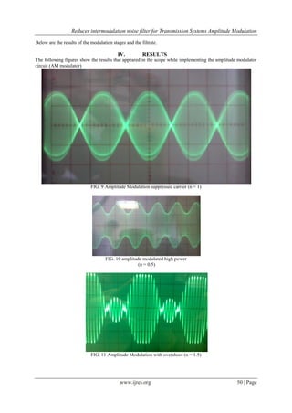
To verify that the filter was audibly and effectively functioning the following scheme was implemented based
on PEAQ established by the International Telecommunications Union. This process is performed by calculating
a correlation of the signal obtained from the expected signal.
FIG. 9 Schemeproposed PEAQ
Table 2. Comparative metrics of the original signal to the expected
Perception Grade PEAQ
Imperceptible 0 a -1
Slightly perceptible -1.1 a -2
Perceptible -2.1 a -3
Very perceptible -3.1 a -4](https://image.slidesharecdn.com/h3104551-151128072742-lva1-app6891/85/Reducer-intermodulation-noise-filter-for-Transmission-Systems-Amplitude-Modulation-5-320.jpg)
![Reducer intermodulation noise filter for Transmission Systems Amplitude Modulation
www.ijres.org 51 | Page
FIG. 11 Response band pass filter
V. CONCLUSIONS
The band pass filters are formed by two filters: a high pass and a low pass connected in series, for
example one after the other.
In this project we do not consider the ripple factor as it is being considered onlyfor ideal answers of modulation
and filtering, so that is why these calculations do not appear within the work
The values of the electronic devices used are not exactly what we use in the actual implementation due to non-
market values, so we decided to bring them closer to the values that are tradable and that may be for sale
Intermodulation noise is a problem that has been afflicting mainly AM modulation schemes because of their
vulnerability.
BIBLIOGRAPHIC REFERENCES
[1]. Couch W. Leon, "Digital Communication Systems and Analog”, 7ª Edition, Prentice Hall.
[2]. Chen-hao Qi, et. al., “Hybrid Modulation for AM Broadcasting”, Third International Conference on
Natural Computation, 2007
[3]. Ghoshal, S., et. al., “Modeling amplitude-modulated (AM) tone encoding behavior of cochlear nucleus
neurons”, Seventeenth Annual Northeast Bioengineering Conference, 2005
[4]. Fahmi Bin, Hussin, Bin Yon, “Readability of Amplitude Modulation (AM) detector laboratory sheet,
International RF and Microwave Conference, 2011
AUTHOR PROFILE:
Carlos Aquino Ruiz was born in Mexico on April 2, 1973 is in Communications and
Electronics Engineering from the National Polytechnic Institute IPN, a research professor and
areas of development are applied computing, data networking and security.
Dolores Zamorano Saavedra. She is a methodological research and has master's degree in
Educational Sciences. Nowadays it is a research professor at the School of Mechanical and
Electrical Engineering (ESIME) in Mexico. Her areas of development are assessment and
project development, scientific writing and methodology of science
Celedonio Enrique Aguilar Meza was born in Mexico on march 3, 1959 and holds a degree
in communications and electronics from the National Polytechnic Institute IPN, is currently
research professor and development areas are the processing and handling, coding and
compression, safety and efficient transmission.](https://image.slidesharecdn.com/h3104551-151128072742-lva1-app6891/85/Reducer-intermodulation-noise-filter-for-Transmission-Systems-Amplitude-Modulation-7-320.jpg)

This document discusses the impact of intermodulation noise on amplitude modulation (AM) transmission systems and presents a designed filter aimed at reducing such noise. The proposed intermodulation noise filter operates effectively, ensuring that the modulated signal retains a quality level with minimal perceptible noise. The results demonstrate the filter's capability to improve AM system performance, addressing a long-standing challenge in broadcasting technology.