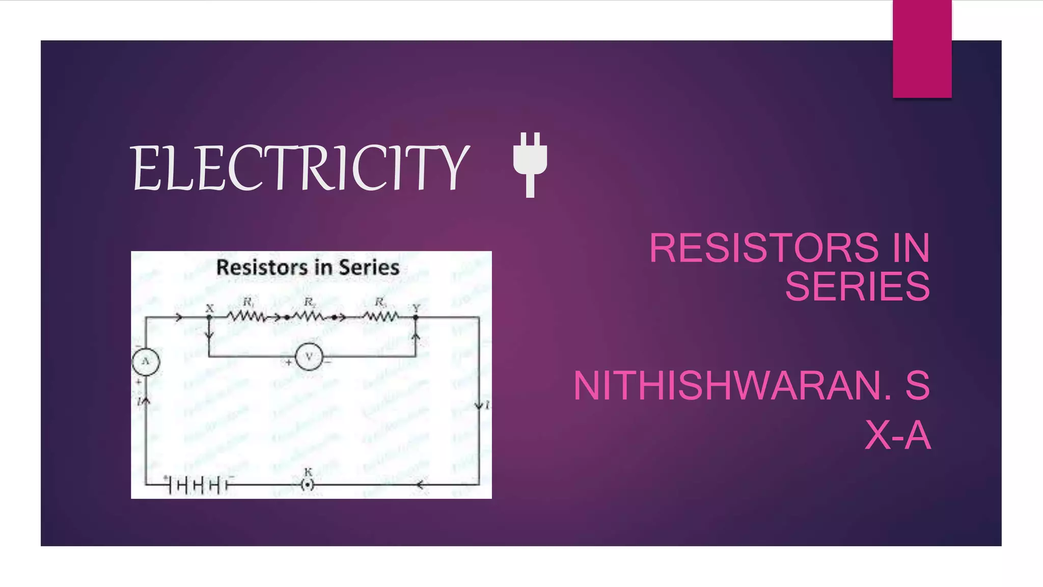
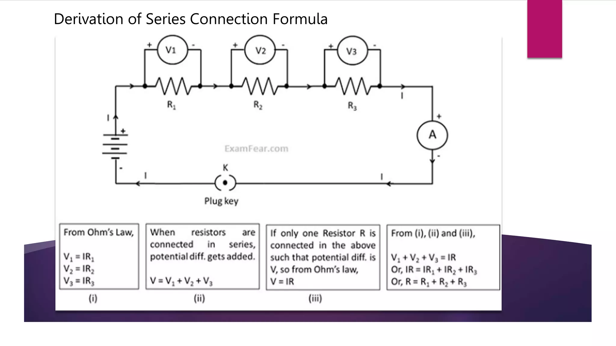
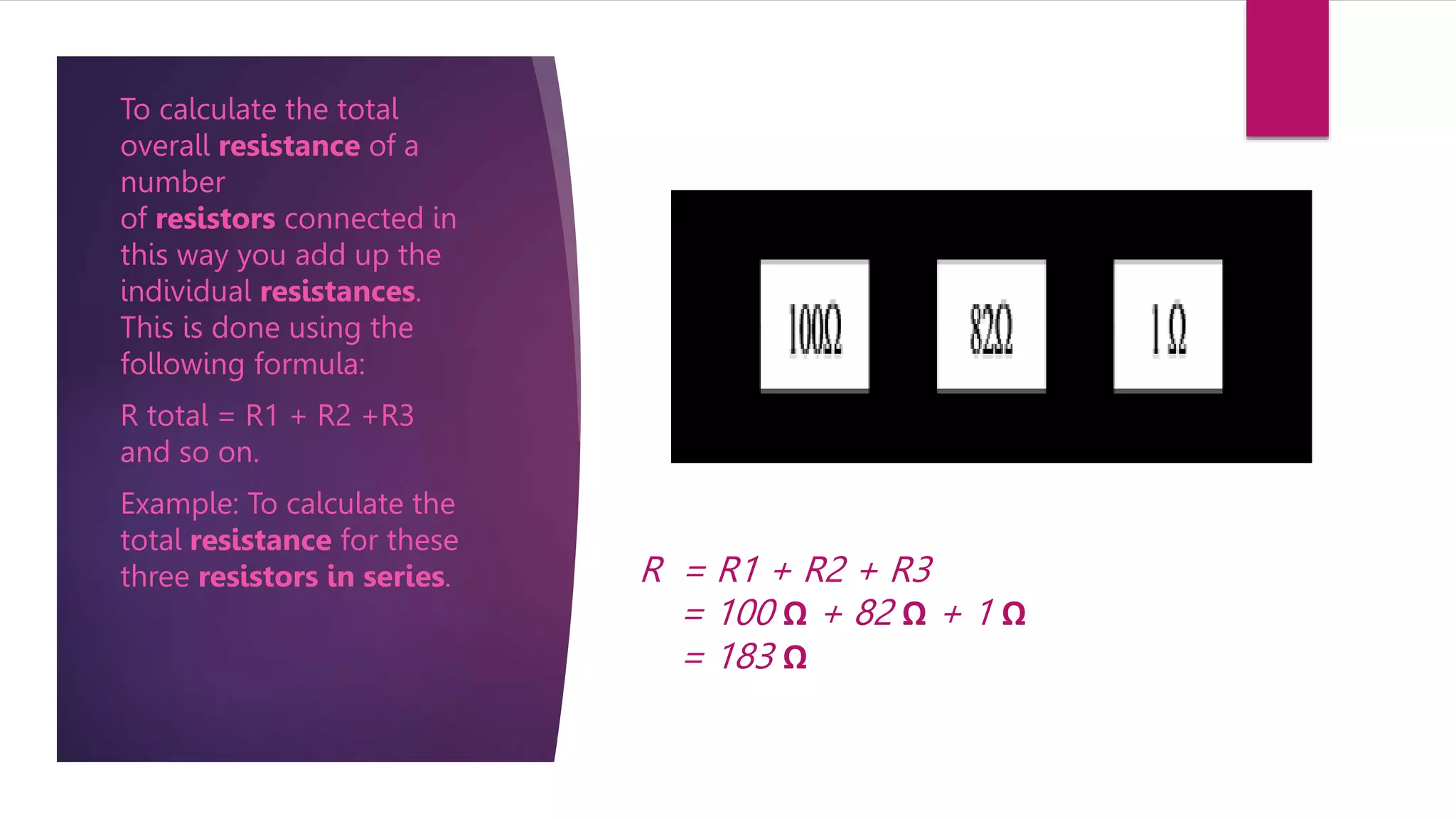
ELECTRICITY 🔌
RESISTORS IN
SERIES
NITHISHWARAN. S
X-A
Combination of Resistors
 Resistors in Series
When resistors are joined from end to end, it is called in series.
 Resistors in Parallel
When resistors are joined in parallel, the reciprocal of the total resistance of the
system is equal to the sum of reciprocal of the resistance of resistors.
 Here , we are going to see about Resistors in series connection.
Resistors in Series
A circuit is said to be connected in series when the same
amount of current flows through the resistors. In such circuits,
the voltage across each resistor is different. In a series
connection, if any resistor is broken or a fault occurs, then the
entire circuit is turned off. The construction of a series circuit is
simpler compared to a parallel circuit.
Real Life Series Connection Examples
Light Switch
Christmas lights
Advantages of Series Connection
Problems In Series Connection
A series circuit is also known as end to end connection, in which a several resistance are connected
together with one after the other. There is a single path for the flow of current.
 In series connection, if two bulbs are connected then both the bulbs will be dimmer as compared to
their original voltage.
 In series connection, we cannot switch off only one device without turning both off.
 There will be chances of short circuiting because loss of current or overflowing of current.
 Series connection can damage the electrical appliance due to flow of huge amount of current which
may be not required by that appliance.
 If one electrical appliance stops working because of a serial circuit fault, then all devices will stop
functioning.
Derivation of Series Connection Formula
R = R1 + R2 + R3
= 100 Ω + 82 Ω + 1 Ω
= 183 Ω
To calculate the total
overall resistance of a
number
of resistors connected in
this way you add up the
individual resistances.
This is done using the
following formula:
R total = R1 + R2 +R3
and so on.
Example: To calculate the
total resistance for these
three resistors in series.
Problem
 There are three resistors joined in series in a system having resistance equal to 10 Ω, 20 Ω and 30 Ω
respectively. If the potential difference of the circuit is 240 V, find the total resistance and current
through the circuit.
 Solution:
 Given, R1 = 10 Ω, R2 = 20 Ω, R3 = 30 Ω and V = 240 V
 Total resistance (R) = ?
 Current through the circuit ( I ) = ?
 According to Ohm’s Law Total resistance in series (R) = Sum of resistance of all resistors
 Or, R = 10Ω + 20Ω + 30Ω = 60Ω
 We know that electric current I=V/R
 Or, I=240V÷60Ω=4A
 Thus, total resistance (R)=60Ω
 Current through the circuit = 4 A
THANK YOU
HAVE A MARVELLOUS DAY

Resistors in Series.pptx

  • 1.
  • 2.
    Combination of Resistors Resistors in Series When resistors are joined from end to end, it is called in series.  Resistors in Parallel When resistors are joined in parallel, the reciprocal of the total resistance of the system is equal to the sum of reciprocal of the resistance of resistors.  Here , we are going to see about Resistors in series connection.
  • 3.
    Resistors in Series Acircuit is said to be connected in series when the same amount of current flows through the resistors. In such circuits, the voltage across each resistor is different. In a series connection, if any resistor is broken or a fault occurs, then the entire circuit is turned off. The construction of a series circuit is simpler compared to a parallel circuit.
  • 4.
    Real Life SeriesConnection Examples Light Switch Christmas lights
  • 5.
  • 6.
    Problems In SeriesConnection A series circuit is also known as end to end connection, in which a several resistance are connected together with one after the other. There is a single path for the flow of current.  In series connection, if two bulbs are connected then both the bulbs will be dimmer as compared to their original voltage.  In series connection, we cannot switch off only one device without turning both off.  There will be chances of short circuiting because loss of current or overflowing of current.  Series connection can damage the electrical appliance due to flow of huge amount of current which may be not required by that appliance.  If one electrical appliance stops working because of a serial circuit fault, then all devices will stop functioning.
  • 7.
    Derivation of SeriesConnection Formula
  • 8.
    R = R1+ R2 + R3 = 100 Ω + 82 Ω + 1 Ω = 183 Ω To calculate the total overall resistance of a number of resistors connected in this way you add up the individual resistances. This is done using the following formula: R total = R1 + R2 +R3 and so on. Example: To calculate the total resistance for these three resistors in series.
  • 9.
    Problem  There arethree resistors joined in series in a system having resistance equal to 10 Ω, 20 Ω and 30 Ω respectively. If the potential difference of the circuit is 240 V, find the total resistance and current through the circuit.  Solution:  Given, R1 = 10 Ω, R2 = 20 Ω, R3 = 30 Ω and V = 240 V  Total resistance (R) = ?  Current through the circuit ( I ) = ?  According to Ohm’s Law Total resistance in series (R) = Sum of resistance of all resistors  Or, R = 10Ω + 20Ω + 30Ω = 60Ω  We know that electric current I=V/R  Or, I=240V÷60Ω=4A  Thus, total resistance (R)=60Ω  Current through the circuit = 4 A
  • 10.
    THANK YOU HAVE AMARVELLOUS DAY