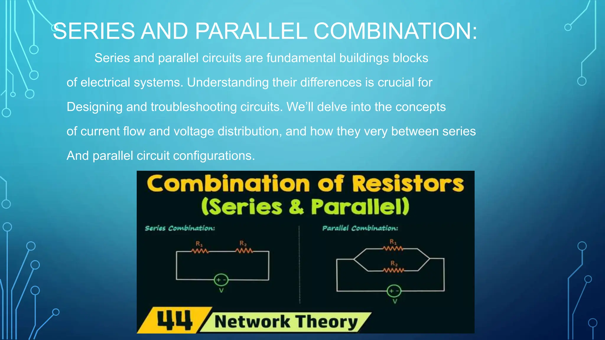
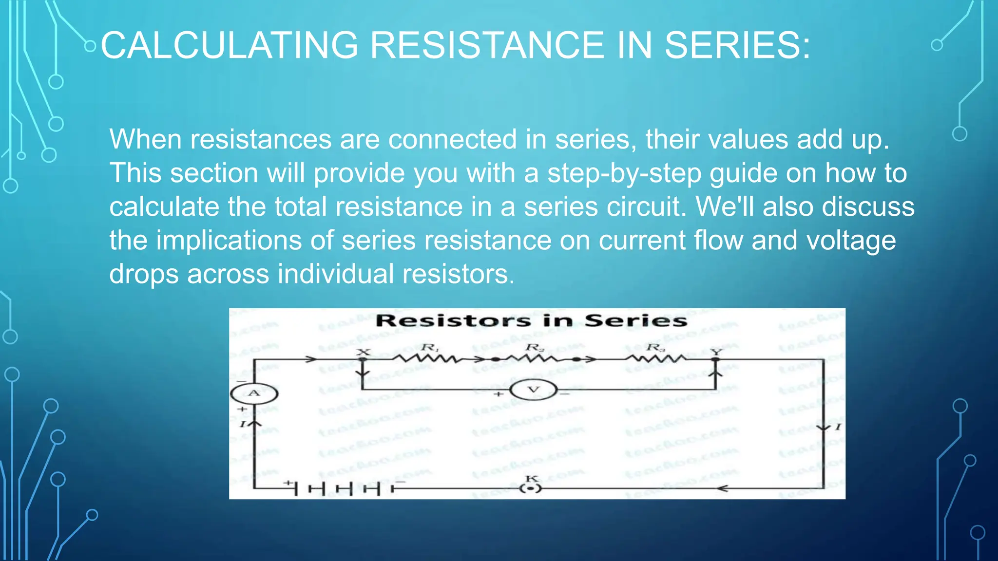
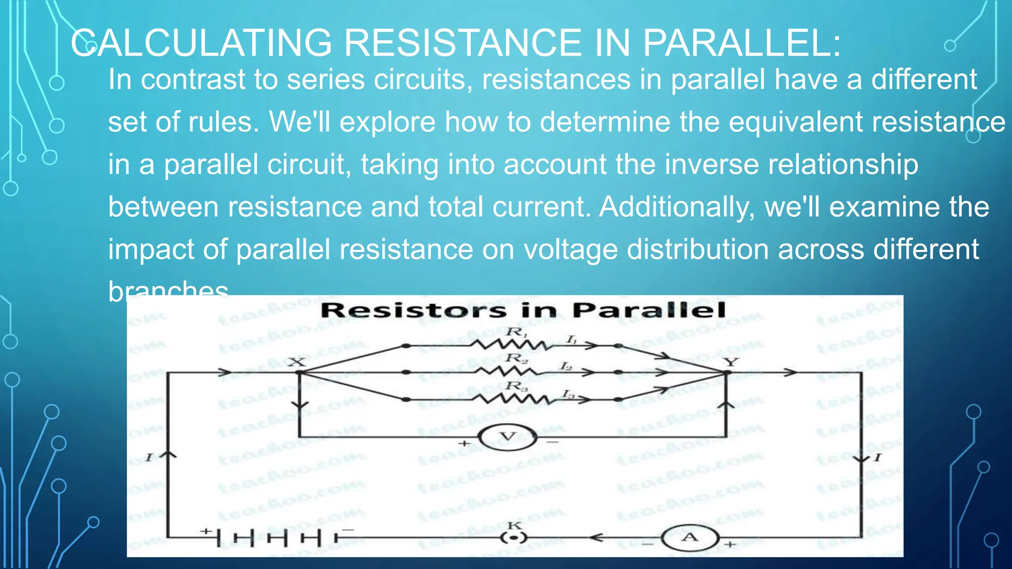
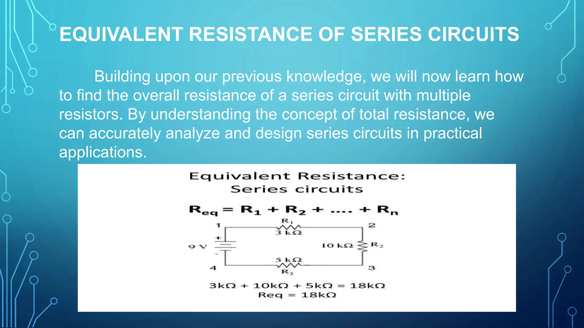
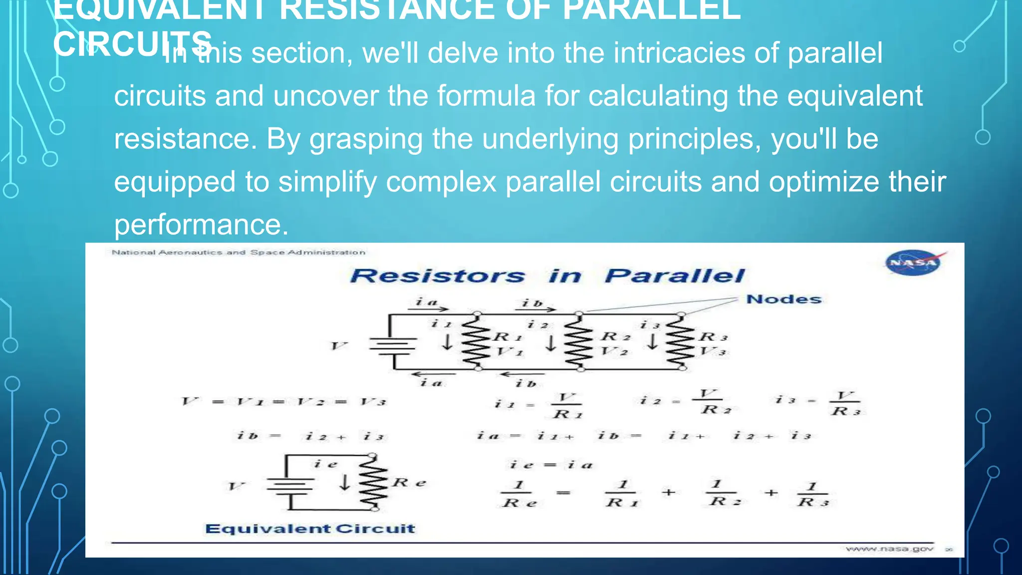
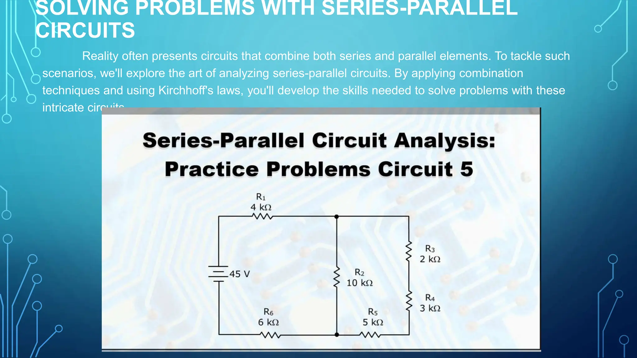
1. The document discusses series circuits and how voltage is divided among resistors in series. It explains that the total resistance of resistors in series is equal to the sum of the individual resistances.
2. A key concept covered is the voltage divider rule - the voltage across each resistor in a series circuit is directly proportional to the ratio of its resistance to the total resistance.
3. Applications of voltage dividers include using potentiometers (variable resistors) to obtain a variable output voltage from a fixed voltage source.
Resistors can be connected in series, parallel, or a combination of both. In series, the total resistance is the sum of individual resistances. In parallel, the total resistance is lower than the lowest individual resistance. Complex circuits can be reduced to an equivalent single resistance by repeatedly replacing series or parallel sections with equivalent components. This allows complicated circuits to be analyzed easily using Ohm's law.
Lab 5 BASIC CIRCUITS( Resistors, Voltage,and Current with.docxfestockton
Lab 5: BASIC CIRCUITS
( Resistors, Voltage,
and Current with MATLAB adapted from P-178 DC Circuit Labs )
Introduction
:
Electric circuits can be defined as closed or continuous paths in which electric currents are confined and around which electric currents can be caused to flow. Electrical circuits are an essential part of daily living, and may be found in heavy and light industry, commercial installations and operations, and residential applications. Modern life and its many conveniences seem inconceivable without the use of electric circuits.
The total resistance of a circuit is the sum of the individual resistances of the power source, the wiring, and the load. The load resistance is generally much higher than either the resistance of the power source or the wiring. The resistances of the wiring are usually neglected in classroom laboratory experiments. Very rarely is circuit wiring significant in experimental work. In these cases we consider the loads resistances to be the only resistance. Wiring resistance may be considerable in the case of transmission cables, as well as telephone lines, which are many miles long, and we have a lab which investigates and calculates the resistance in such cables and the lost power and energy due to these lengths.
If an arbitrary load of relatively low resistance were connected to an existing power supply or voltage source, an excessive current might flow to the load, causing burn up or other malfunctions with the load and wiring.
The current can be reduced
by reducing the source voltage, but this is not always feasible and is frequently impossible. The resistances of the voltage source or the load could be increased, but these are usually built right into the source or load. Resistances of connecting wires are so low that miles would be needed to increase the circuit resistance by more than a few dozen ohms. A selection of materials for connecting wires might be useful, but a better method would be to creation of a device that is specifically a resistor that can be included with the circuit to give the net or total resistance needed to provide the desired current for the voltage source involved.
In any DC circuit, the total current is equal to the power source voltage divided by the total or equivalent resistance. For a Series Circuit, this is the only current. This means that if the current in some portion of the circuit is known, the total current and the current through every part of the circuit is known. The sum of the voltage drops across the resistors in series is equal to the power supply voltage.
In Parallel Circuits, the total current from the power source divides into different paths as in approaches the parallel branches. The voltage drop across parallel branches is the same for all the branches. If the voltage drop for one branch is known, the voltage drop for all the parallel branches is known.
The sum of the currents in the various branches is equal to the current from the po.
This document discusses resistors in series connections. It defines a series connection as resistors joined end to end so that the same current flows through each resistor. The total resistance of resistors in series is calculated by adding the individual resistances. Examples of series connections include light switches and Christmas lights. Advantages are simpler construction compared to parallel circuits, but problems include any single resistor failure causing the whole circuit to fail and uneven current draw lowering efficiency. A sample calculation finds the total resistance and current for a series circuit with three specified resistors and a given voltage.
A High Performance PWM Voltage Source Inverter Used for VAR Compensation and ...IJMER
International Journal of Modern Engineering Research (IJMER) is Peer reviewed, online Journal. It serves as an international archival forum of scholarly research related to engineering and science education.
This document defines key terms and concepts related to electrical circuits and networks. It discusses different types of circuits including linear/non-linear, bilateral/unilateral circuits. It also defines electrical networks and their components such as nodes, branches, loops and meshes. Finally, it covers important circuit analysis techniques including Ohm's law, Kirchhoff's laws, mesh analysis, nodal analysis and superposition theorem.
This document provides instructions for navigating a presentation on electric circuits. It begins with an overview slide and table of contents. It then covers topics like schematic diagrams, components of electric circuits, and calculating equivalent resistances and currents in series and parallel circuits. Examples are provided, such as calculating the equivalent resistance and current in a complex circuit.
This document discusses resistors in series and parallel circuits. It defines series and parallel circuits, provides diagrams of each, and derives the formulas for calculating equivalent resistance in series (sum of individual resistances) and parallel (reciprocal of the sum of reciprocals of individual resistances) circuits. It concludes by giving examples of applications of resistors in heating elements, lighting, and automotive components.
This document provides an introduction and overview of electronics concepts including:
- A review of short circuits, series vs parallel circuits, resistance, and basic components like resistors, switches, batteries, breadboards.
- Descriptions of key electronics terms like resistance, resistors, switches, batteries and how they function in circuits. Resistors add resistance, switches open and close circuits, batteries store power.
- An assignment to build circuits using resistors, batteries, switches, an LED, speaker, transistor, potentiometer and integrated circuit on a breadboard to apply the concepts learned.
This document discusses series circuits and Kirchhoff's voltage law. It begins by introducing direct current and resistance in series circuits. It then explains that the total resistance of components in series is the sum of the individual resistances. Kirchhoff's voltage law states that the algebraic sum of the potential rises and drops around any closed loop is equal to zero. This means that the applied voltage in a series circuit equals the sum of the voltage drops across the individual elements. The document provides examples of applying Kirchhoff's voltage law to solve for voltages in series circuits.
The document discusses resistors in series, parallel, and simple networks. It provides the cardinal rules for series and parallel circuits, including that the total resistance in a series circuit equals the sum of individual resistances, and the total current in a parallel circuit equals the sum of branch currents. Examples are given of calculating total resistance, current, and voltage drops in series and parallel circuits. Kirchhoff's laws of voltage and current are also summarized.
This document discusses resistors and resistor combinations in circuits. It covers resistor types including fixed and variable resistors. It also covers resistor color codes and examples of resistors in series and parallel combinations. The key topics are resistances and their combinations in series and parallel and how to calculate equivalent resistances for complex resistor networks using Ohm's law.
This document discusses Kirchhoff's Current Law (KCL) and how to calculate equivalent resistance in parallel circuits. It defines KCL as the principle that the sum of currents entering a node must equal the sum of currents leaving that node. The document then explains how KCL is used to analyze electrical circuits by determining unknown currents. It also defines equivalent resistance in parallel circuits as the combined resistance of multiple resistors connected across the same voltage source. A formula is provided to calculate equivalent resistance using individual resistances. Finally, the document derives the formula and provides an example circuit calculation.
The document discusses modeling eddy current effects in transformer windings and cores for electromagnetic transient simulations. It describes existing methods and their limitations. New lumped parameter models are presented that accurately represent eddy currents in windings and laminated cores up to high frequencies with low model order. Tests show the models provide appropriate damping effects during transient simulations by capturing the underlying physical phenomena of eddy currents in transformers.
Sheet1ResistorcolorResistance (kohms)40 ohm resistor39.94 ohm1brown black yellow silver1322red1823brown green orange13.34brown gray orange gold18.35green1836blue black red gold60.67orange blue orange gold34.4k ohmsmeasured resistanceSeries Circuit1,2,5497.498Mohms3,4,76666Kohms1,6,5375.6.377Mohms7,3,4,2248248KohmsK ohms TheoreticalParallel1,2,553.95543,4,76.2936.31,5,633.8533.92,3,4,76.086.09HybridK ohms TheoreticalK ohms observed1 in series 2 and 5 in parallel223.2223.93 in series and 4 and 7 in parallel25.225.21 in series and 6 and 5 in parallel177.5178
Sheet2Characteristic CurvemVmALight bulb3.83.336.933.861.75590.377118951521131901292491463501635501819522091440228153023425702844070345-0.05-0.056-6.51-5.98-13.2-12.1-25.8-23.7-54.4-48.9-95.5-80.6-126-101-395-168-327-159-211-134-784-195-531-178-1570-236-2500-281-4060-345
3.8 36.9 61.7 90.3 118 152 190 249 350 550 952 1440 1530 2570 4070 -0.05 -6.51 -13.2 -25.8 -54.4 -95.5 -126 -395 -327 -211 -784 -531 -1570 -2500 -4060 3.3 33.799999999999997 55 77 95 113 129 146 163 181 209 228 234 284 345 -5.6000000000000001E-2 -5.98 -12.1 -23.7 -48.9 -80.599999999999994 -101 -168 -159 -134 -195 -178 -236 -281 -345
Sheet3Characteristic CurvemVmADiode2.330.032.930.0370.0370016732307443976867.77931218142008302918444263.160.034.540.0324.40.03700.031860.032700.045821.156172.396504.86666.844320.06-2.340.02-260.02-320.03-9900.04
2.33 2.93 7 700 732 744 768 793 814 830 844 3.16 4.54 24.4 70 186 270 582 617 650 666 432 -2.34 -26 -32 -990 0.03 0.03 0.03 16 30 39 67.7 121 200 291 426 0.03 0.03 0.03 0.03 0.03 0.04 1.1499999999999999 2.39 4.8 6.84 0.06 0.02 0.02 0.03 0.04
Sheet5Characteristic CurveResistormVmA132k ohms2.28-0.00131-0.00115602320.0015300.0037220.00411110.00719900.01423600.01752000.03965400.04994300.071178000.135-2.32-0.001-33-0.001-283-0.003-1120-0.01-1850-0.015-3040-0.024-6940-0.054-10500-0.082-17800-0.138
2.2799999999999998 31 156 232 530 722 1111 1990 2360 5200 6540 9430 17800 -2.3199999999999998 -33 -283 -1120 -1850 -3040 -6940 -10500 -17800 -1E-3 -1E-3 0 1E-3 3.0000000000000001E-3 4.0000000000000001E-3 7.0000000000000001E-3 1.4E-2 1.7000000000000001E-2 3.9E-2 4.9000000000000002E-2 7.0999999999999994E-2 0.13500000000000001 -1E-3 -1E-3 -3.0000000000000001E-3 -0.01 -1.4999999999999999E-2 -2.4E-2 -5.3999999999999999E-2 -8.2000000000000003E-2 -0.13800000000000001
Resistor Circuits and Characteristic Curves
Purpose: In this lab we will introduce basic circuit analysis with series and parallel resistor circuits using Ohms Law and Kirchhoff’s laws. We will also introduce characteristic curves and diodes.
Introduction: Ohm’s Law is of general use with circuit elements, with parts of circuits, or with whole circuits. The voltage across a circuit element is equal to the resistance (or equivalent resistance) times the current flowing through the element. (V=IR)
Kirchhoff’s 1st Law of Circuits: The sum of voltages around a closed loop is equal to zero.
0
i
n
V
i = 1
=
å
“S.
The document is an abstract from the International Journal of Electrical Engineering and Technology discussing fault analysis on a three-phase, three-level grid-connected photovoltaic system. It presents models for the key components of the system - the photovoltaic array, three-level inverter, distribution network, and control algorithms. Dynamic models are developed in MATLAB/Simulink to simulate the system and analyze faults. The models account for factors like irradiance and temperature that impact photovoltaic output. Space vector pulse width modulation is used to reduce harmonic content from the three-level inverter. Simulation results are said to verify the effectiveness of the control system under different operating conditions.
1) Kirchhoff's rules, based on conservation of energy and charge, can be used to analyze more complex circuits that cannot be reduced to a single equivalent resistor. The junction rule states that the sum of currents at a junction is zero, while the loop rule states that the sum of potential differences around a closed loop is zero.
2) To solve circuit problems using Kirchhoff's rules, the problem solver draws the circuit, assigns variables to unknowns, chooses current directions, writes equations using the junction and loop rules, and solves the equations simultaneously.
3) Circuits containing capacitors require analysis of how the current changes over time as the capacitor charges and discharges.
The document provides an introduction to basic electronics components and concepts such as series and parallel circuits, resistance, resistors, switches, batteries, short circuits, breadboards, and homework involving common electronic parts. Key points covered include:
- Series circuits have components wired one after another, while parallel circuits have components wired side by side.
- Resistance controls the flow of electricity according to Ohm's Law. Resistors are used to add resistance and reduce current flow.
- Switches open or close circuits to control the flow of electricity. Batteries store and provide electrical power.
- Breadboards are used to prototype circuits and have rows to connect integrated circuit pins. Homework involves typical electronic parts like resistors, batteries
The Impact of Line Resistance on the Performance of Controllable Series Compe...Editor Jacotech
In recent years controllable FACTS devices are increasingly
integrated into the transmission system. FACTS devices that
provide series control such as Controllable Series Compensator
(CSC) has significant effect on the voltage stability of Electric
Power system. In this work impact of line resistance on the
performance of CSC in a single-load infinitive-bus (SLIB)
model is investigated. The proposed framework is applied to
SLIB model and obtained results demonstrates that line
resistance has considerable effect on voltage stability limits and
performance of CSC.
1) Direct current circuits containing batteries, resistors, and capacitors are analyzed using techniques like Kirchhoff's rules. Kirchhoff's junction rule states the sum of currents at a junction is zero, based on charge conservation. Kirchhoff's loop rule states the sum of potential differences around a closed loop is zero, based on energy conservation.
2) Resistors can be in series or parallel. Series resistors have the same current and added potentials, yielding a higher total resistance. Parallel resistors have the same potential and varying currents, yielding a lower total resistance.
3) RC circuits contain resistors and capacitors. A charging capacitor draws current that decays exponentially with the time constant RC. A discharging capacitor supplies
This document provides an overview of circuits and discusses single-loop circuits. Some key points:
- An emf device, like a battery, maintains a potential difference between its terminals by doing work on charge carriers as they flow from the negative to positive terminal.
- In a single-loop circuit with a battery and resistor, the battery drives current through the resistor from high to low potential.
- Using the energy method, the work done by the battery equals the thermal energy dissipated in the resistor, allowing the current to be calculated.
- Using the potential method and Kirchhoff's loop rule, the sum of potential differences around any complete loop must be zero, also allowing the
Fault identification in transformer windingeSAT Journals
This document discusses fault identification in transformer windings during impulse testing. It presents an analysis of transformer winding current waveforms using both time-domain and frequency-domain (Fast Fourier Transform) methods to classify insulation failures. Simulation results are shown for a range of distribution transformer models with different fault types created at various locations. The proposed approach is applied to an analog model of a 12kVA single-phase transformer, with faults detected by analyzing the neutral currents under applied low voltage impulses.
IJRET : International Journal of Research in Engineering and Technology is an international peer reviewed, online journal published by eSAT Publishing House for the enhancement of research in various disciplines of Engineering and Technology. The aim and scope of the journal is to provide an academic medium and an important reference for the advancement and dissemination of research results that support high-level learning, teaching and research in the fields of Engineering and Technology. We bring together Scientists, Academician, Field Engineers, Scholars and Students of related fields of Engineering and Technology.
Home security is of paramount importance in today's world, where we rely more on technology, home
security is crucial. Using technology to make homes safer and easier to control from anywhere is
important. Home security is important for the occupant’s safety. In this paper, we came up with a low cost,
AI based model home security system. The system has a user-friendly interface, allowing users to start
model training and face detection with simple keyboard commands. Our goal is to introduce an innovative
home security system using facial recognition technology. Unlike traditional systems, this system trains
and saves images of friends and family members. The system scans this folder to recognize familiar faces
and provides real-time monitoring. If an unfamiliar face is detected, it promptly sends an email alert,
ensuring a proactive response to potential security threats.
More Related Content
Similar to series paralle combination of cirucuits with diagram
This document provides instructions for navigating a presentation on electric circuits. It begins with an overview slide and table of contents. It then covers topics like schematic diagrams, components of electric circuits, and calculating equivalent resistances and currents in series and parallel circuits. Examples are provided, such as calculating the equivalent resistance and current in a complex circuit.
This document discusses resistors in series and parallel circuits. It defines series and parallel circuits, provides diagrams of each, and derives the formulas for calculating equivalent resistance in series (sum of individual resistances) and parallel (reciprocal of the sum of reciprocals of individual resistances) circuits. It concludes by giving examples of applications of resistors in heating elements, lighting, and automotive components.
This document provides an introduction and overview of electronics concepts including:
- A review of short circuits, series vs parallel circuits, resistance, and basic components like resistors, switches, batteries, breadboards.
- Descriptions of key electronics terms like resistance, resistors, switches, batteries and how they function in circuits. Resistors add resistance, switches open and close circuits, batteries store power.
- An assignment to build circuits using resistors, batteries, switches, an LED, speaker, transistor, potentiometer and integrated circuit on a breadboard to apply the concepts learned.
This document discusses series circuits and Kirchhoff's voltage law. It begins by introducing direct current and resistance in series circuits. It then explains that the total resistance of components in series is the sum of the individual resistances. Kirchhoff's voltage law states that the algebraic sum of the potential rises and drops around any closed loop is equal to zero. This means that the applied voltage in a series circuit equals the sum of the voltage drops across the individual elements. The document provides examples of applying Kirchhoff's voltage law to solve for voltages in series circuits.
The document discusses resistors in series, parallel, and simple networks. It provides the cardinal rules for series and parallel circuits, including that the total resistance in a series circuit equals the sum of individual resistances, and the total current in a parallel circuit equals the sum of branch currents. Examples are given of calculating total resistance, current, and voltage drops in series and parallel circuits. Kirchhoff's laws of voltage and current are also summarized.
This document discusses resistors and resistor combinations in circuits. It covers resistor types including fixed and variable resistors. It also covers resistor color codes and examples of resistors in series and parallel combinations. The key topics are resistances and their combinations in series and parallel and how to calculate equivalent resistances for complex resistor networks using Ohm's law.
This document discusses Kirchhoff's Current Law (KCL) and how to calculate equivalent resistance in parallel circuits. It defines KCL as the principle that the sum of currents entering a node must equal the sum of currents leaving that node. The document then explains how KCL is used to analyze electrical circuits by determining unknown currents. It also defines equivalent resistance in parallel circuits as the combined resistance of multiple resistors connected across the same voltage source. A formula is provided to calculate equivalent resistance using individual resistances. Finally, the document derives the formula and provides an example circuit calculation.
The document discusses modeling eddy current effects in transformer windings and cores for electromagnetic transient simulations. It describes existing methods and their limitations. New lumped parameter models are presented that accurately represent eddy currents in windings and laminated cores up to high frequencies with low model order. Tests show the models provide appropriate damping effects during transient simulations by capturing the underlying physical phenomena of eddy currents in transformers.
Sheet1ResistorcolorResistance (kohms)40 ohm resistor39.94 ohm1brown black yellow silver1322red1823brown green orange13.34brown gray orange gold18.35green1836blue black red gold60.67orange blue orange gold34.4k ohmsmeasured resistanceSeries Circuit1,2,5497.498Mohms3,4,76666Kohms1,6,5375.6.377Mohms7,3,4,2248248KohmsK ohms TheoreticalParallel1,2,553.95543,4,76.2936.31,5,633.8533.92,3,4,76.086.09HybridK ohms TheoreticalK ohms observed1 in series 2 and 5 in parallel223.2223.93 in series and 4 and 7 in parallel25.225.21 in series and 6 and 5 in parallel177.5178
Sheet2Characteristic CurvemVmALight bulb3.83.336.933.861.75590.377118951521131901292491463501635501819522091440228153023425702844070345-0.05-0.056-6.51-5.98-13.2-12.1-25.8-23.7-54.4-48.9-95.5-80.6-126-101-395-168-327-159-211-134-784-195-531-178-1570-236-2500-281-4060-345
3.8 36.9 61.7 90.3 118 152 190 249 350 550 952 1440 1530 2570 4070 -0.05 -6.51 -13.2 -25.8 -54.4 -95.5 -126 -395 -327 -211 -784 -531 -1570 -2500 -4060 3.3 33.799999999999997 55 77 95 113 129 146 163 181 209 228 234 284 345 -5.6000000000000001E-2 -5.98 -12.1 -23.7 -48.9 -80.599999999999994 -101 -168 -159 -134 -195 -178 -236 -281 -345
Sheet3Characteristic CurvemVmADiode2.330.032.930.0370.0370016732307443976867.77931218142008302918444263.160.034.540.0324.40.03700.031860.032700.045821.156172.396504.86666.844320.06-2.340.02-260.02-320.03-9900.04
2.33 2.93 7 700 732 744 768 793 814 830 844 3.16 4.54 24.4 70 186 270 582 617 650 666 432 -2.34 -26 -32 -990 0.03 0.03 0.03 16 30 39 67.7 121 200 291 426 0.03 0.03 0.03 0.03 0.03 0.04 1.1499999999999999 2.39 4.8 6.84 0.06 0.02 0.02 0.03 0.04
Sheet5Characteristic CurveResistormVmA132k ohms2.28-0.00131-0.00115602320.0015300.0037220.00411110.00719900.01423600.01752000.03965400.04994300.071178000.135-2.32-0.001-33-0.001-283-0.003-1120-0.01-1850-0.015-3040-0.024-6940-0.054-10500-0.082-17800-0.138
2.2799999999999998 31 156 232 530 722 1111 1990 2360 5200 6540 9430 17800 -2.3199999999999998 -33 -283 -1120 -1850 -3040 -6940 -10500 -17800 -1E-3 -1E-3 0 1E-3 3.0000000000000001E-3 4.0000000000000001E-3 7.0000000000000001E-3 1.4E-2 1.7000000000000001E-2 3.9E-2 4.9000000000000002E-2 7.0999999999999994E-2 0.13500000000000001 -1E-3 -1E-3 -3.0000000000000001E-3 -0.01 -1.4999999999999999E-2 -2.4E-2 -5.3999999999999999E-2 -8.2000000000000003E-2 -0.13800000000000001
Resistor Circuits and Characteristic Curves
Purpose: In this lab we will introduce basic circuit analysis with series and parallel resistor circuits using Ohms Law and Kirchhoff’s laws. We will also introduce characteristic curves and diodes.
Introduction: Ohm’s Law is of general use with circuit elements, with parts of circuits, or with whole circuits. The voltage across a circuit element is equal to the resistance (or equivalent resistance) times the current flowing through the element. (V=IR)
Kirchhoff’s 1st Law of Circuits: The sum of voltages around a closed loop is equal to zero.
0
i
n
V
i = 1
=
å
“S.
The document is an abstract from the International Journal of Electrical Engineering and Technology discussing fault analysis on a three-phase, three-level grid-connected photovoltaic system. It presents models for the key components of the system - the photovoltaic array, three-level inverter, distribution network, and control algorithms. Dynamic models are developed in MATLAB/Simulink to simulate the system and analyze faults. The models account for factors like irradiance and temperature that impact photovoltaic output. Space vector pulse width modulation is used to reduce harmonic content from the three-level inverter. Simulation results are said to verify the effectiveness of the control system under different operating conditions.
1) Kirchhoff's rules, based on conservation of energy and charge, can be used to analyze more complex circuits that cannot be reduced to a single equivalent resistor. The junction rule states that the sum of currents at a junction is zero, while the loop rule states that the sum of potential differences around a closed loop is zero.
2) To solve circuit problems using Kirchhoff's rules, the problem solver draws the circuit, assigns variables to unknowns, chooses current directions, writes equations using the junction and loop rules, and solves the equations simultaneously.
3) Circuits containing capacitors require analysis of how the current changes over time as the capacitor charges and discharges.
The document provides an introduction to basic electronics components and concepts such as series and parallel circuits, resistance, resistors, switches, batteries, short circuits, breadboards, and homework involving common electronic parts. Key points covered include:
- Series circuits have components wired one after another, while parallel circuits have components wired side by side.
- Resistance controls the flow of electricity according to Ohm's Law. Resistors are used to add resistance and reduce current flow.
- Switches open or close circuits to control the flow of electricity. Batteries store and provide electrical power.
- Breadboards are used to prototype circuits and have rows to connect integrated circuit pins. Homework involves typical electronic parts like resistors, batteries
The Impact of Line Resistance on the Performance of Controllable Series Compe...Editor Jacotech
In recent years controllable FACTS devices are increasingly
integrated into the transmission system. FACTS devices that
provide series control such as Controllable Series Compensator
(CSC) has significant effect on the voltage stability of Electric
Power system. In this work impact of line resistance on the
performance of CSC in a single-load infinitive-bus (SLIB)
model is investigated. The proposed framework is applied to
SLIB model and obtained results demonstrates that line
resistance has considerable effect on voltage stability limits and
performance of CSC.
1) Direct current circuits containing batteries, resistors, and capacitors are analyzed using techniques like Kirchhoff's rules. Kirchhoff's junction rule states the sum of currents at a junction is zero, based on charge conservation. Kirchhoff's loop rule states the sum of potential differences around a closed loop is zero, based on energy conservation.
2) Resistors can be in series or parallel. Series resistors have the same current and added potentials, yielding a higher total resistance. Parallel resistors have the same potential and varying currents, yielding a lower total resistance.
3) RC circuits contain resistors and capacitors. A charging capacitor draws current that decays exponentially with the time constant RC. A discharging capacitor supplies
1) Direct current circuits containing batteries, resistors, and capacitors are analyzed using techniques like Kirchhoff's rules. Kirchhoff's junction rule states the sum of currents at a junction is zero, based on charge conservation. Kirchhoff's loop rule states the sum of potential differences around a closed loop is zero, based on energy conservation.
2) Resistors can be in series or parallel. Series resistors have the same current and added potentials, yielding a higher total resistance. Parallel resistors have the same potential and varying currents, yielding a lower total resistance.
3) RC circuits contain resistors and capacitors. A charging capacitor draws current that decays exponentially with the time constant RC. A discharging capacitor supplies
This document provides an overview of circuits and discusses single-loop circuits. Some key points:
- An emf device, like a battery, maintains a potential difference between its terminals by doing work on charge carriers as they flow from the negative to positive terminal.
- In a single-loop circuit with a battery and resistor, the battery drives current through the resistor from high to low potential.
- Using the energy method, the work done by the battery equals the thermal energy dissipated in the resistor, allowing the current to be calculated.
- Using the potential method and Kirchhoff's loop rule, the sum of potential differences around any complete loop must be zero, also allowing the
Fault identification in transformer windingeSAT Journals
This document discusses fault identification in transformer windings during impulse testing. It presents an analysis of transformer winding current waveforms using both time-domain and frequency-domain (Fast Fourier Transform) methods to classify insulation failures. Simulation results are shown for a range of distribution transformer models with different fault types created at various locations. The proposed approach is applied to an analog model of a 12kVA single-phase transformer, with faults detected by analyzing the neutral currents under applied low voltage impulses.
IJRET : International Journal of Research in Engineering and Technology is an international peer reviewed, online journal published by eSAT Publishing House for the enhancement of research in various disciplines of Engineering and Technology. The aim and scope of the journal is to provide an academic medium and an important reference for the advancement and dissemination of research results that support high-level learning, teaching and research in the fields of Engineering and Technology. We bring together Scientists, Academician, Field Engineers, Scholars and Students of related fields of Engineering and Technology.
Similar to series paralle combination of cirucuits with diagram (20)
Home security is of paramount importance in today's world, where we rely more on technology, home
security is crucial. Using technology to make homes safer and easier to control from anywhere is
important. Home security is important for the occupant’s safety. In this paper, we came up with a low cost,
AI based model home security system. The system has a user-friendly interface, allowing users to start
model training and face detection with simple keyboard commands. Our goal is to introduce an innovative
home security system using facial recognition technology. Unlike traditional systems, this system trains
and saves images of friends and family members. The system scans this folder to recognize familiar faces
and provides real-time monitoring. If an unfamiliar face is detected, it promptly sends an email alert,
ensuring a proactive response to potential security threats.
Height and depth gauge linear metrology.pdfq30122000
Height gauges may also be used to measure the height of an object by using the underside of the scriber as the datum. The datum may be permanently fixed or the height gauge may have provision to adjust the scale, this is done by sliding the scale vertically along the body of the height gauge by turning a fine feed screw at the top of the gauge; then with the scriber set to the same level as the base, the scale can be matched to it. This adjustment allows different scribers or probes to be used, as well as adjusting for any errors in a damaged or resharpened probe.
Mechatronics is a multidisciplinary field that refers to the skill sets needed in the contemporary, advanced automated manufacturing industry. At the intersection of mechanics, electronics, and computing, mechatronics specialists create simpler, smarter systems. Mechatronics is an essential foundation for the expected growth in automation and manufacturing.
Mechatronics deals with robotics, control systems, and electro-mechanical systems.
Software Engineering and Project Management - Software Testing + Agile Method...Prakhyath Rai
Software Testing: A Strategic Approach to Software Testing, Strategic Issues, Test Strategies for Conventional Software, Test Strategies for Object -Oriented Software, Validation Testing, System Testing, The Art of Debugging.
Agile Methodology: Before Agile – Waterfall, Agile Development.
DEEP LEARNING FOR SMART GRID INTRUSION DETECTION: A HYBRID CNN-LSTM-BASED MODELijaia
As digital technology becomes more deeply embedded in power systems, protecting the communication
networks of Smart Grids (SG) has emerged as a critical concern. Distributed Network Protocol 3 (DNP3)
represents a multi-tiered application layer protocol extensively utilized in Supervisory Control and Data
Acquisition (SCADA)-based smart grids to facilitate real-time data gathering and control functionalities.
Robust Intrusion Detection Systems (IDS) are necessary for early threat detection and mitigation because
of the interconnection of these networks, which makes them vulnerable to a variety of cyberattacks. To
solve this issue, this paper develops a hybrid Deep Learning (DL) model specifically designed for intrusion
detection in smart grids. The proposed approach is a combination of the Convolutional Neural Network
(CNN) and the Long-Short-Term Memory algorithms (LSTM). We employed a recent intrusion detection
dataset (DNP3), which focuses on unauthorized commands and Denial of Service (DoS) cyberattacks, to
train and test our model. The results of our experiments show that our CNN-LSTM method is much better
at finding smart grid intrusions than other deep learning algorithms used for classification. In addition,
our proposed approach improves accuracy, precision, recall, and F1 score, achieving a high detection
accuracy rate of 99.50%.
Software Engineering and Project Management - Introduction, Modeling Concepts...Prakhyath Rai
Introduction, Modeling Concepts and Class Modeling: What is Object orientation? What is OO development? OO Themes; Evidence for usefulness of OO development; OO modeling history. Modeling
as Design technique: Modeling, abstraction, The Three models. Class Modeling: Object and Class Concept, Link and associations concepts, Generalization and Inheritance, A sample class model, Navigation of class models, and UML diagrams
Building the Analysis Models: Requirement Analysis, Analysis Model Approaches, Data modeling Concepts, Object Oriented Analysis, Scenario-Based Modeling, Flow-Oriented Modeling, class Based Modeling, Creating a Behavioral Model.
Digital Twins Computer Networking Paper Presentation.pptxaryanpankaj78
A Digital Twin in computer networking is a virtual representation of a physical network, used to simulate, analyze, and optimize network performance and reliability. It leverages real-time data to enhance network management, predict issues, and improve decision-making processes.
Build the Next Generation of Apps with the Einstein 1 Platform.
Rejoignez Philippe Ozil pour une session de workshops qui vous guidera à travers les détails de la plateforme Einstein 1, l'importance des données pour la création d'applications d'intelligence artificielle et les différents outils et technologies que Salesforce propose pour vous apporter tous les bénéfices de l'IA.
Supermarket Management System Project Report.pdfKamal Acharya
Supermarket management is a stand-alone J2EE using Eclipse Juno program.
This project contains all the necessary required information about maintaining
the supermarket billing system.
The core idea of this project to minimize the paper work and centralize the
data. Here all the communication is taken in secure manner. That is, in this
application the information will be stored in client itself. For further security the
data base is stored in the back-end oracle and so no intruders can access it.
Discover the latest insights on Data Driven Maintenance with our comprehensive webinar presentation. Learn about traditional maintenance challenges, the right approach to utilizing data, and the benefits of adopting a Data Driven Maintenance strategy. Explore real-world examples, industry best practices, and innovative solutions like FMECA and the D3M model. This presentation, led by expert Jules Oudmans, is essential for asset owners looking to optimize their maintenance processes and leverage digital technologies for improved efficiency and performance. Download now to stay ahead in the evolving maintenance landscape.
series paralle combination of cirucuits with diagram
1. SERIES AND PARALLEL COMBINATION:
Series and parallel circuits are fundamental buildings blocks
of electrical systems. Understanding their differences is crucial for
Designing and troubleshooting circuits. We’ll delve into the concepts
of current flow and voltage distribution, and how they very between series
And parallel circuit configurations.
2. CALCULATING RESISTANCE IN SERIES:
When resistances are connected in series, their values add up.
This section will provide you with a step-by-step guide on how to
calculate the total resistance in a series circuit. We'll also discuss
the implications of series resistance on current flow and voltage
drops across individual resistors.
3. CALCULATING RESISTANCE IN PARALLEL:
In contrast to series circuits, resistances in parallel have a different
set of rules. We'll explore how to determine the equivalent resistance
in a parallel circuit, taking into account the inverse relationship
between resistance and total current. Additionally, we'll examine the
impact of parallel resistance on voltage distribution across different
branches.
4. EQUIVALENT RESISTANCE OF SERIES CIRCUITS
Building upon our previous knowledge, we will now learn how
to find the overall resistance of a series circuit with multiple
resistors. By understanding the concept of total resistance, we
can accurately analyze and design series circuits in practical
applications.
5. EQUIVALENT RESISTANCE OF PARALLEL
CIRCUITS
In this section, we'll delve into the intricacies of parallel
circuits and uncover the formula for calculating the equivalent
resistance. By grasping the underlying principles, you'll be
equipped to simplify complex parallel circuits and optimize their
performance.
6. SOLVING PROBLEMS WITH SERIES-PARALLEL
CIRCUITS
Reality often presents circuits that combine both series and parallel elements. To tackle such
scenarios, we'll explore the art of analyzing series-parallel circuits. By applying combination
techniques and using Kirchhoff's laws, you'll develop the skills needed to solve problems with these
intricate circuits.
7. REAL-WORLD APPLICATIONS OF SERIES-
PARALLEL CIRCUITS
Series-parallel circuits are ubiquitous in everyday life. From home wiring to
industrial machinery, understanding their applications is essential. We'll examine
practical examples, such as power distribution systems, electronic devices, and
even renewable energy systems, to showcase the relevance and impact of series-
parallel circuits in our modern world.