
Recommended
More Related Content
What's hot
What's hot (20)
Similar to A system of resistors
Similar to A system of resistors (20)
Recently uploaded
A system of resistors
- 2. CONTENT INTRODUCTION. RESISTOR OF SERIES. DERIVATION OF RESISTOR OF SERIES. DIAGRAM OF RESISTOR OF SERIES. RESISTOR OF PARALLEL. DERIVATION OF RESISTOR OF PARALLEL. DIAGRAM OF RESISTOR OF PARALLEL. APLLICATIONS OF RESISTOR.
- 3. INTRODUCTION The current through a conductor depends upon its resistance And potential difference across its ends. In various electrical Gadgets, we often use resistors in various combination. We now therefore intend to see how Ohm’s law can be applied to combination of resistors. There are two type of resistors:- Resistor of Series Resistor of Parallel
- 4. RESISTOR OF SERIES Series Circuits are sometimes called current- coupled or daisy chain-coupled. The current in a series circuit goes through every component in the circuit. Therefore all of the components in a series connection carry the same current. There is only one path in a series circuit in which the current can flow. The formula to search resistance is Rs = R1 +R2 +R3 +…….+Rn
- 5. DERIVATION OF RESISTOR OF SERIES Given that V= V1 + V2 +V3 (i) I= the current Applying the Ohm’s law to the entire circuit ,we have V=IR On applying Ohm’s law to the three resistors separately, we further Have V1=I R1 V2=I R2 V3=I R3 From equation (i) I R= I R1 +I R2 +I R3 or RS=R1 + R2 + R3 We conclude that when several resistor are joined in series, the resistance of the combination Rs equals the sum of their individual resistances, R1,R2,R3 and thus greater than any individual resistance
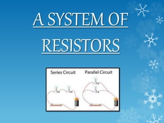
- 6. DIAGRAM OF RESISTOR OF SERIES Electric circuit in which three resistors having resistances R1, R2 and R3 respectively are joined together in a series. Here the resistors are said to be connected in series.
- 7. RESISTOR OF PARALLEL Two or more components are connected in parallel they have the same potential difference (voltage) across their ends. The potential differences across the components are the same in magnitude, and they also have identical polarities. The same voltage is applicable to all circuit components connected in parallel. The total current is the sum of the currents through the individual components, in accordance with KIRCHHOFF’s current law
- 8. DIAGRAM OF RESISTOR OF PARALLEL Electric circuit in which three resistors having resistances R1, R2 and R3 respectively are joined parallel to each other. Here the resistors are said to be connected as parallels.
- 9. DERIVATION OF RESISTOR OF PARALLEL Given that I=the total current I= I1 +I2 +I3 (i) RP be the equivalent resistance of the parallel By applying Ohm’s law to the parallel combination of resistance we have I =V/RP (ii) On applying Ohm’s law to each resistor, we have I=V/R1; I2= V/R2; and I3 =V/R3 (iii) From equation (i) to(iii) we have V/RP= V/R1 + V/R2 + V/R3 or 1/RP= 1/R1 + I/R2 + 1/R3 We may conclude that the reciprocal of the equivalent resistance of a group of resistances joined in parallel is equal to the sum of the reciprocals of the individual resistance.
- 10. APLLICATIONS OF RESISTOR The principle of resistors can be applied for heating elements in iron, toasters, heaters, and hair dryers which dissipate voltage as heat. New generation auto motive LED lights cluster, demand a specialist resistor solution. Aluminum clad wire wound resistor provide high power dissipation in a limited space and are designed for direct heat sink mounting using thermal compound to achieve maximum performance.