Download to read offline
![International Research Journal of Engineering and Technology (IRJET) e-ISSN: 2395-0056
Volume: 06 Issue: 05 | May 2019 www.irjet.net p-ISSN: 2395-0072
© 2019, IRJET | Impact Factor value: 7.211 | ISO 9001:2008 Certified Journal | Page 6128
Fig.2 Structure of Fuzzy logic Controller
4.1 Fuzzification
The fuzzification makes it possible to pass from the real
variables to fuzzy variables. The actual voltage (V) and
current (I) of PV generator can be measured continuously
and the power can be calculated (P = V×I). The control is
determined on the basis of satisfaction of two criteria
relating to two input variables of proposed controller,
namely error E (which represents the slope of P-I
characteristic) and change of this error (CE), at a sampling
instant k .
The variable E and CE are expressed as follows,
Where P(k) and I(k) are the power and current of the PV
generator, respectively. Therefore, the input E(k) shows if
the operating point at the instant k is located on the left or
on the right of the MPP on the P-I characteristic, while the
input CE(k) expresses the displacement direction of this
point . The change in duty ratio of the DC-DC converter is
used as the output of proposed controller. Therefore, the
control is done by changing this duty ratio according to the
slope E(k) in order to bring back the operation point on the
optimal point where the slope is zero. the input variables of
the fuzzy controller (E, CE) are derived from the actual
signals (e, ce)by multiplying with the corresponding scale
gains (SE, SCE), and then convertedtothelinguistic variables
such as PB (positive big), PS (positive small), Z0 (zero), NS
(negative small), NB (negative big) using basic fuzzy subset.
the membership grades of five basic fuzzy subsets for input
and output variables. Theinterferenceengineapplytherules
to fuzzy logy input to determinethefuzzyoutputs.Therefore
, before the rules can be evaluated the crisp input values
must be fuzzified to obtain the corresponding linguistic
values and the degree to which each part of the antecedent
has been satisfied for each rule [16]. Table.2 shows the rule
table of fuzzy controller, where all the entries of the matrix
are fuzzy sets of error (E), change of error (CE) and change
of duty ratio (∆D) to the converter.
4.2 Defuzzification
It was seen that the inference methods provide a function
for the resulting membership variable; it thus acts of fuzzy
information. Being given that converter DC-DC requires a
precise control signal D at its entry it is necessary to
envisage a transformation of this fuzzy information into
deterministic information, this transformation is called
defuzzification. Defuzzification can be performed normally
by two algorithms: Center of Area (COA) and the Max
Criterion Method (MCM). The most used defuzzification
method is that of the determination of the centre of gravity
(COA) of final combined fuzzy set. The final combined fuzzy
set is defined by the union of all rule output fuzzy set
4.3 Inference engine
The interference ingine apply the rules t the fuzzy inputs
(that where generated from the fuzzification process) to
determine the fuzzy outputs. Therefore ,beforetherulescan
be evaluated , the crisp input values must be fuzzified to
obtain the corresponding linguistic values ( that are
necessary to determine the active or fired rule) and the
degree to which each part of the antecedent has been
satisfied for each rule. Following table shows fuzzy
controller , where all the entries of the matrixarefuzzyset of
error (E) change of error(CE) change ofdutyratio(∆D)tothe
convertor.
The 25 control fuzzy rules included in Table.2 can be
presented in 3-dimensions (3-D) graph as shown in figure.
These rules are employed for the controlling of the DC-DC
buck converter such as the MPP of the PV generator is
reached. As shown in the Table 2, the main idea of the rules
is to bring operating point to the MPP by increase or
decreasing the duty ratio depending on the position of the
operating point from the MPP. If the operating point is
distant from MPP, the duty ratio will be increased or
decreased is largely. Fig.7(b) demonstrates an example of
control rule: IF E is PB AND CE is NB Then ∆D is PB. This
implies that if operating point is distant from MPP towards
left hand side and the change of slope in P- I characteristic is
big in the opposite direction, then the duty ratio is largely
increased.
In general the fuzzy control uses one of the following
methods: Max-Min, Max-Prod, Somme-Prod inference](https://image.slidesharecdn.com/irjet-v6i5840-191010085702/85/IRJET-A-Fuzzy-Logic-Control-Method-for-MPPT-to-Improve-Solar-System-Efficiency-3-320.jpg)
![International Research Journal of Engineering and Technology (IRJET) e-ISSN: 2395-0056
Volume: 06 Issue: 05 | May 2019 www.irjet.net p-ISSN: 2395-0072
© 2019, IRJET | Impact Factor value: 7.211 | ISO 9001:2008 Certified Journal | Page 6129
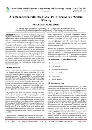
technique. In our case we used the inference method of
Mamdani, which is the Max-Min fuzzy combination.
Fig.3 (a) The input of FLC (Error, E), (b) The input of
FLC (Change of error, CE) (c)The output of FLC (Duty, D).
5. CONCLUSION
In this work, an adaptive fuzzy controller is used to track the
maximum power point in photovoltaic systems. The gain of
the controller is adjusted by fuzzy rules definedonerrorand
change of error. Simulation results show that the proposed
controller can track the maximum power point with better
performances when compared to its conventional
counterpart. Thus the introducing of an adaptive gain in the
structure of conventional fuzzy controllers is well justified.
REFERENCES
[1] Jancarle L. Dos Santos, Fernando L. M. Antunes and Anis
Chehab, "A Maximum Power Point Tracker for PV
Systems Using a High Performance Boost
Converter",Solar Energy, Issue 7,Vol. 80,pp. 772-
778,2005.
[2] Ting-Chung Yu and Tang-Shiuan Chien, "Analysis and
Simulation of Characteristics andMaximumPowerPoint
Tracking for Photovoltaic Systems", Proceedings of
Power Electronics and Drive Systems Conference, pp.
1339 - 1344,Taipei, 2009
[3] Roberto Faranda, Sonia Leva, "Energy Comparison of
MPPT techniques for PV Systems", Wseas Transactions
on Power System, Issue 6, Vol. 3, pp. 446-455, June
2008.
[4] D. P. Hohm and M. E. Ropp, "Comparative Study of
Maximum Power Point Tracking Algorithms using an
experimental, programmable, maximum power point
tracking test bed”, Proceedings of Photovoltaic
Specialists Conference ,pp. 1699 - 1702,USA,2000.
[5] Trishan Esram and Patrick 1. Chapman, "Comparison of
Photovoltaic Array Maximum Power Point Tracking
Techniques", Energy ConverSion, Issue2,Vol.22,pp.439
- 449,May 2007.
[6] V. Salas, E. Olias, A. Barrado, A. Lazaro, "Review of the
Maximum Power Point Tracking Algorithms for Stand-
alone Photo voltaic Systems", Solar Energy Materials
and Solar Cells, Issue 11, Vol. 90,pp. 1555-1578,July
2008.
[7] Castafier, Luis & Santiago Silvestre "Modelling
Photovoltaic Systems using PSpice", John Wiley & Sons
Ltd, 2002.
[8] Walker Geoff, " Evaluating MPPT Converter Topologies
Using a Matlab PV Model ",Journal of Electrical &
Electronics Engineering, Vol. 21,No. 1,pp. 49-55,2011.
[9] Mohan, Undeland and Robbins, "Power Electronics
Converters, Applications and Design" Third Edition,
2003.
BIOGRAPHIES
Lecturer,
Department of Electrical
Engineering,
Sanjay Bhokare Group of Institute
Miraj, Sangli
Assistance Professor,
Department of Electrical
Engineering,
Padmabhushan Vasantraodada
Patil Institute of Technology,
Budhgaon, Sangli.](https://image.slidesharecdn.com/irjet-v6i5840-191010085702/85/IRJET-A-Fuzzy-Logic-Control-Method-for-MPPT-to-Improve-Solar-System-Efficiency-4-320.jpg)

This document presents a fuzzy logic control method for maximum power point tracking (MPPT) to improve the efficiency of solar photovoltaic systems. It proposes using a fuzzy logic controller connected to a boost converter to dynamically adjust the duty cycle based on voltage, current, and power levels from the solar panel. This allows the system to operate at the peak power point despite changing weather conditions. The fuzzy logic controller uses error and change in error as inputs and duty cycle as the output. Simulation results showed this MPPT method can track the maximum power point accurately and outperforms traditional perturbation and observation methods in terms of tracking efficiency and response time.