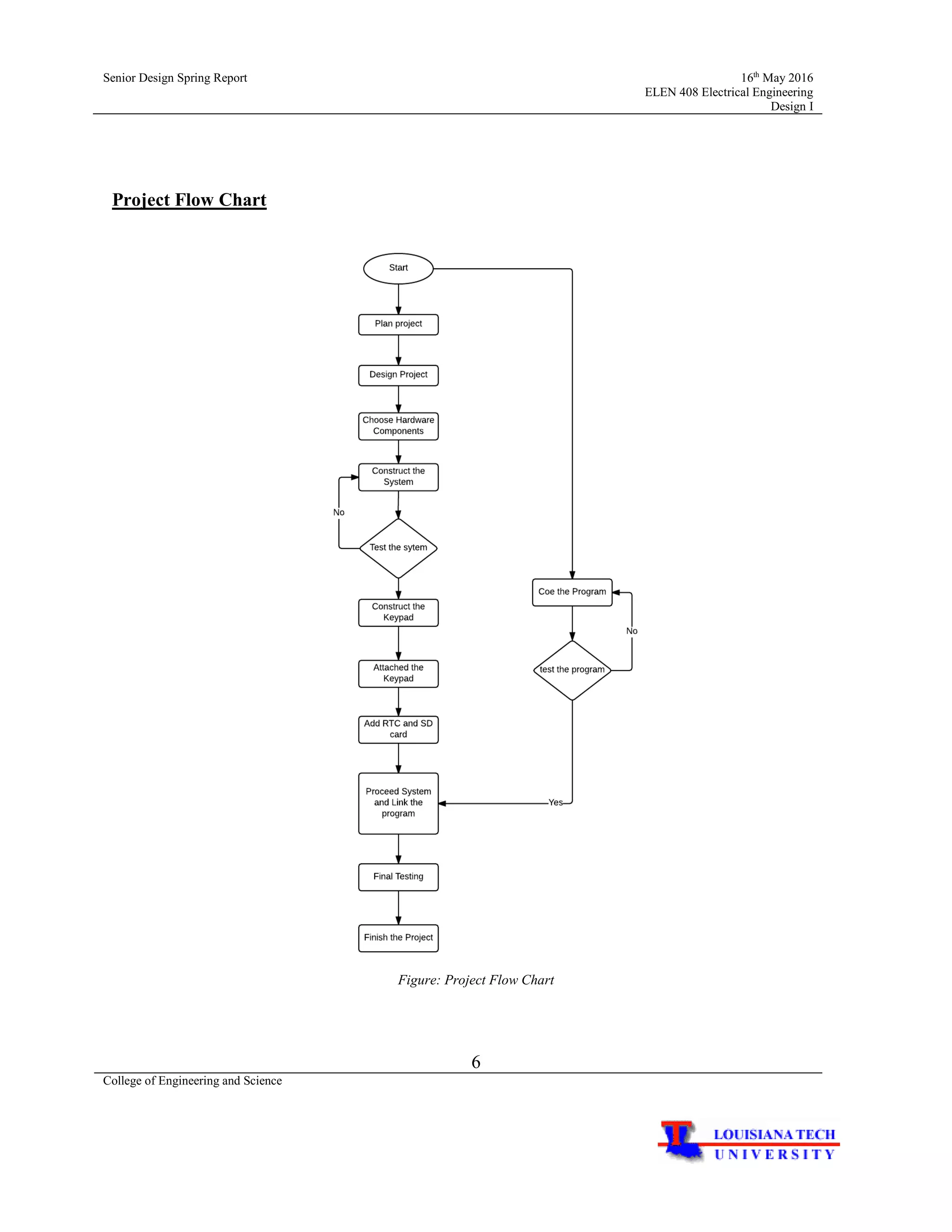
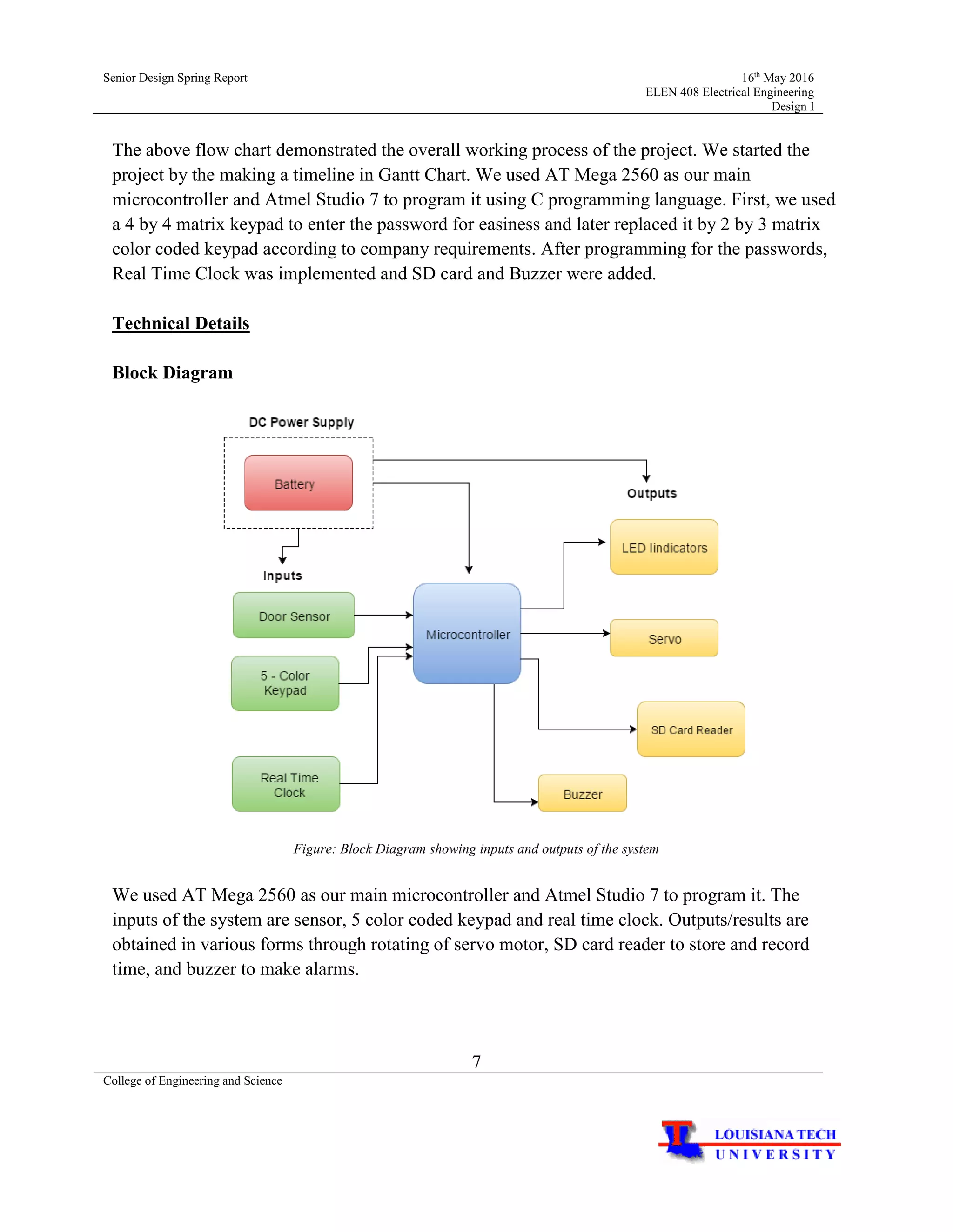
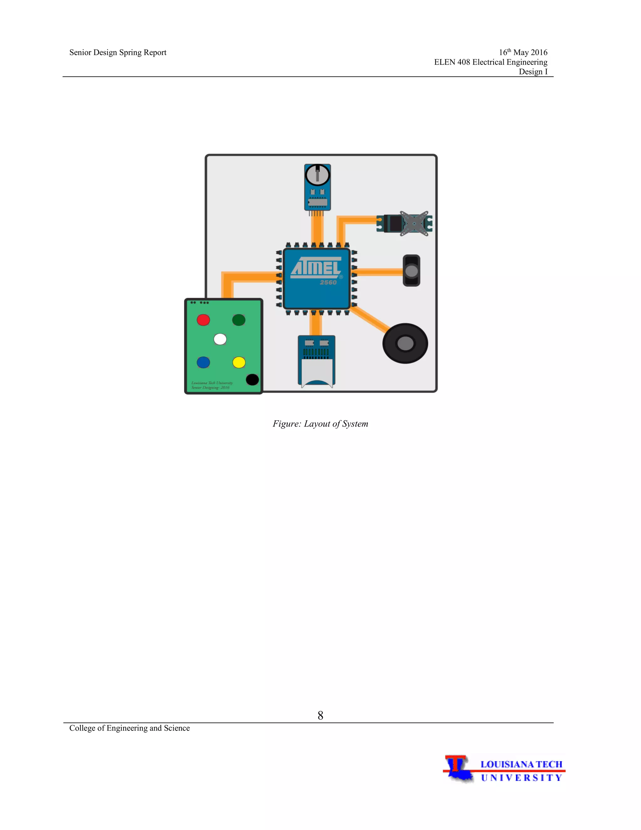
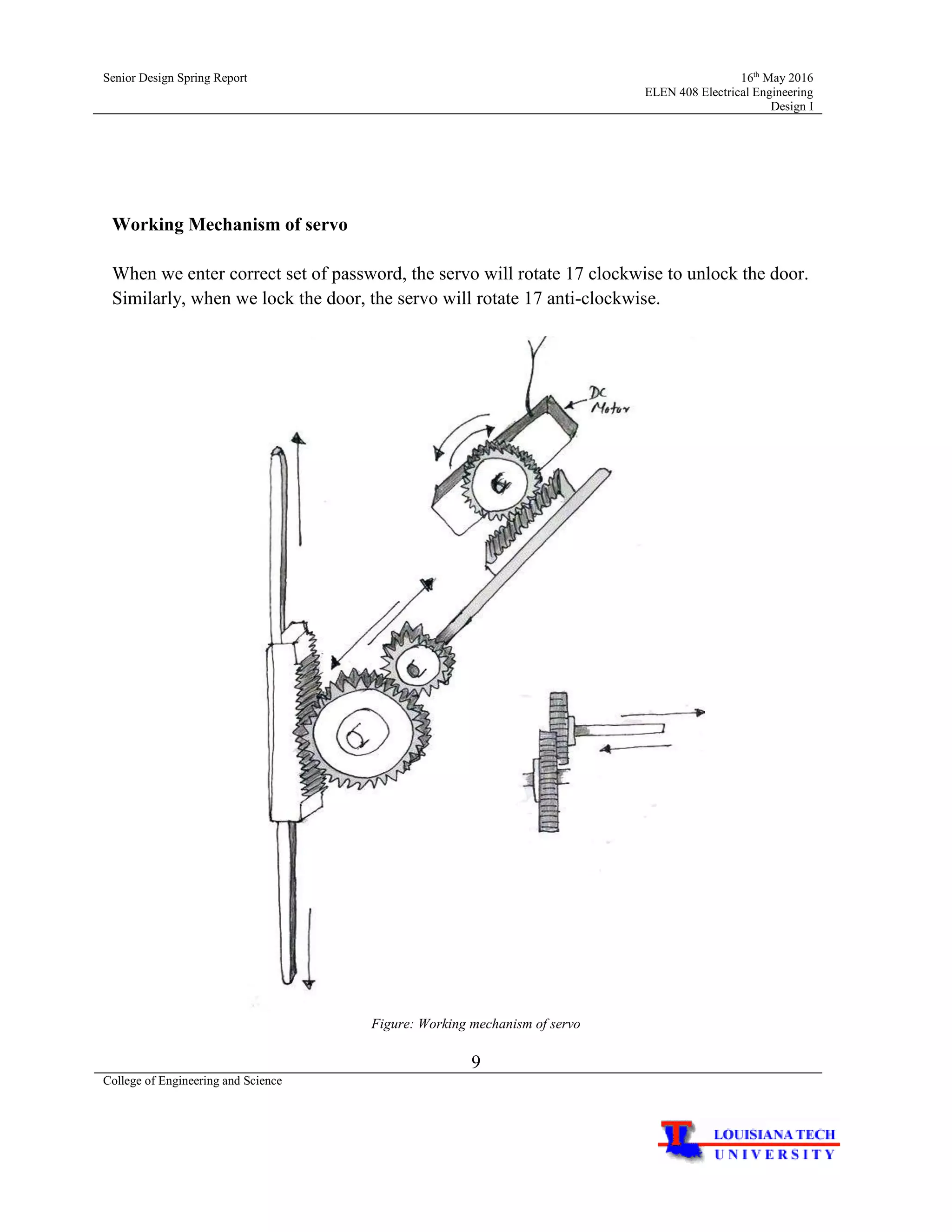
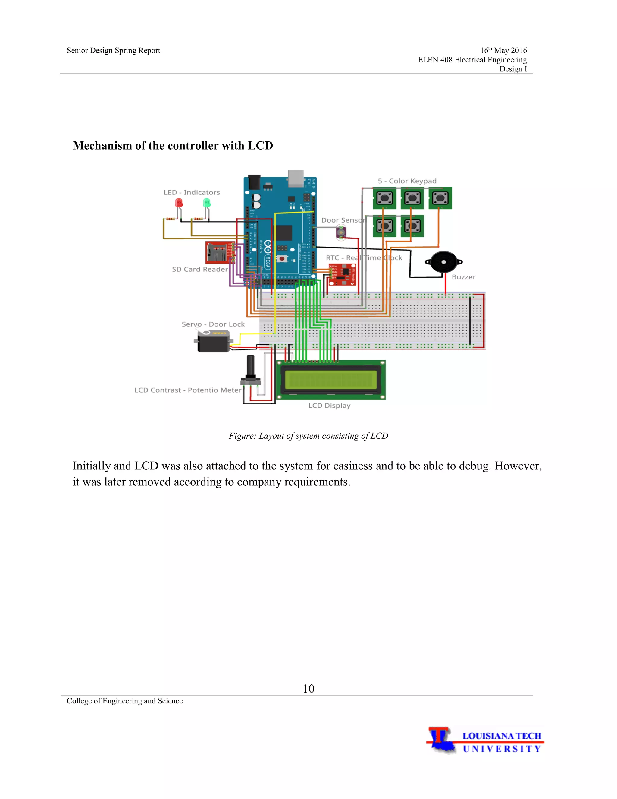
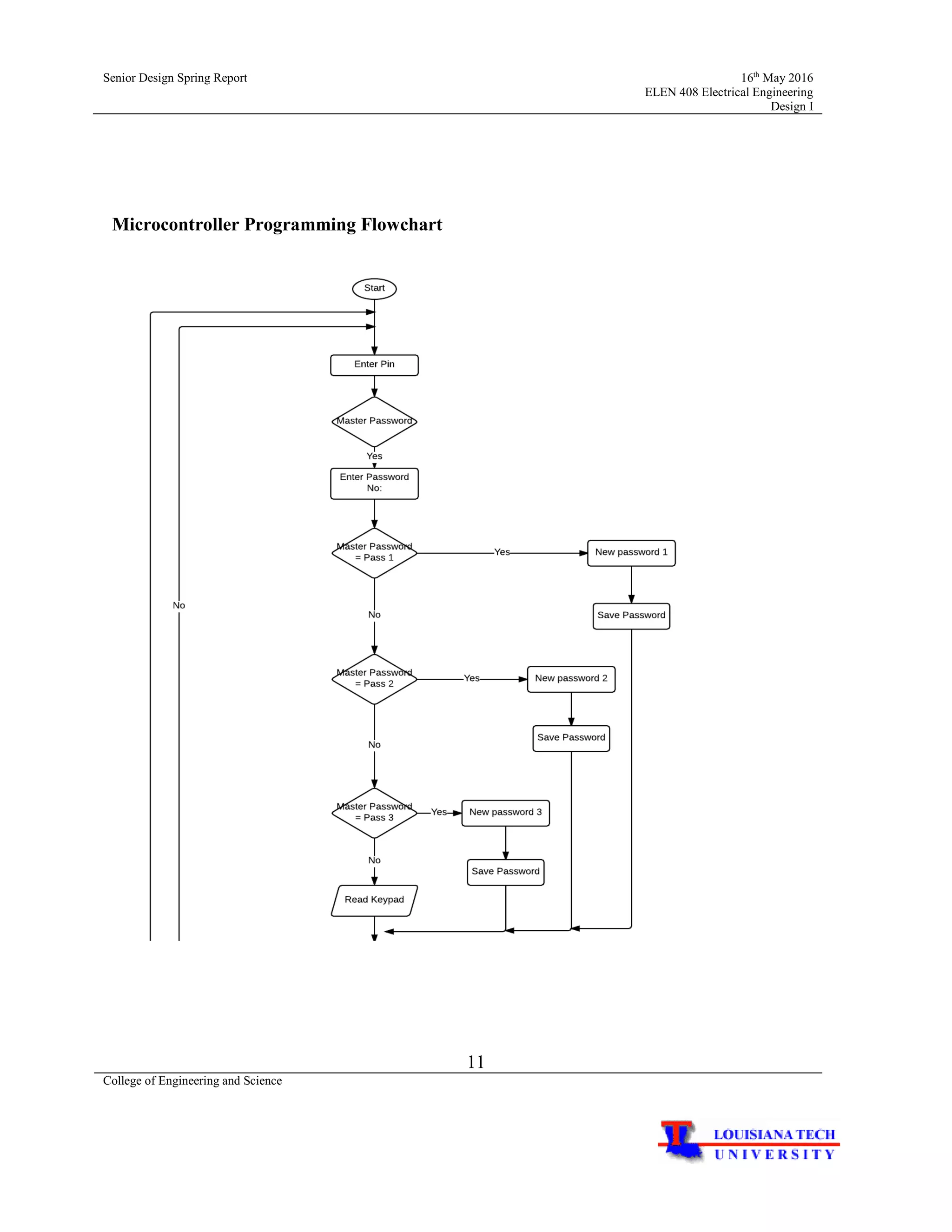
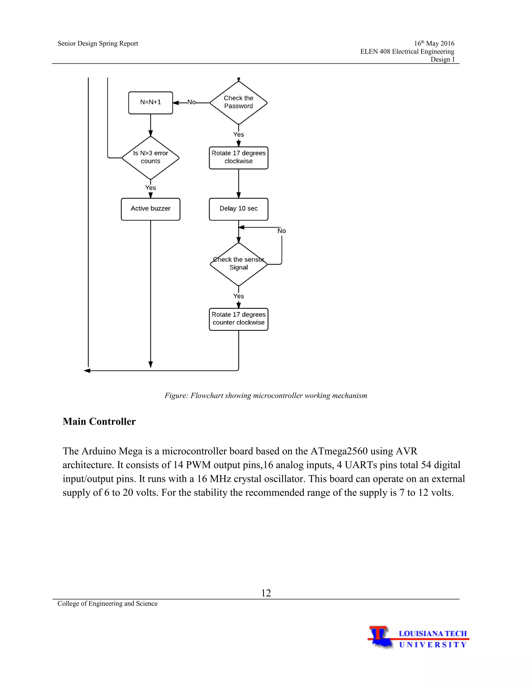
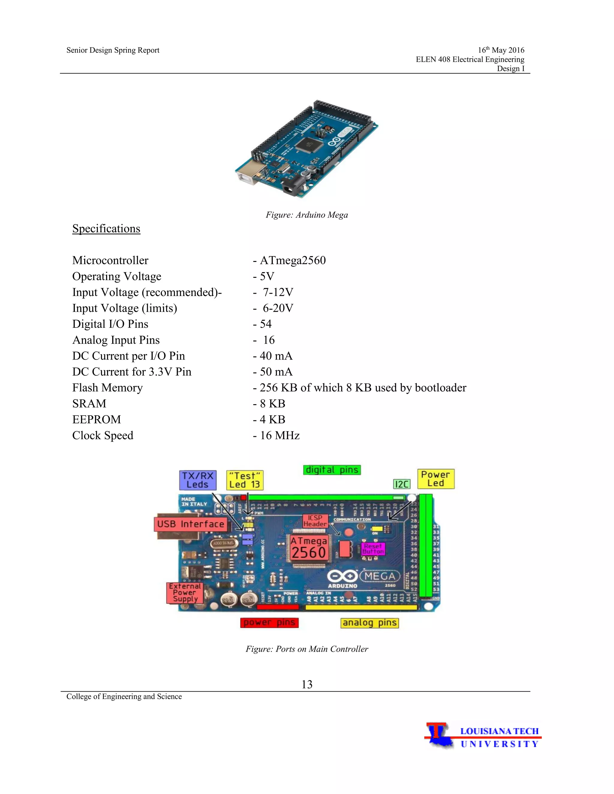
SlideShare a Scribd company logo
College of Engineering and Science
Digital Combination Lock System
ELEN 408
Spring 2016
Names:
Dinuka Kuruppuarachchi
Ruzova Dahal
Jayakody Arachchige
Sponsor Details: The Vacant Property Specialist,
Jake Switzer
(District Sale Manager)
800-918-9100
jacob.switzer@vps360.com
email: www.vps360.com
05/16/2016
Senior Design Spring Report 16th
May 2016
ELEN 408 Electrical Engineering
Design I
2
College of Engineering and Science
Introduction to the Project
This senior design project is carried out for our sponsor company Vacant Property
Security, LLC (VPS) which was founded in 1993. VPS is a trusted leader in securing,
maintaining, and managing vacant properties across a wide range of residential and commercial
sectors. They have locations in Los Angeles, CA, Atlanta, GA, Miami, FL, Chicago, IL, Detroit,
MI, Cleveland, OH, Philadelphia, PA, Newark, NJ, and Dallas, TX. VPS allows customers to
protect their vacant properties against unauthorized access and property decay.
The company’s main goal is to ensure that properties retain their value and provide
customers peace of mind in knowing that their vacant properties are safe and secure. VPS used to
order security doors from a company in UK, which recently stopped manufacturing them. Hence,
our objective was to solve their problem by building a replacement door. The intended purpose
of this project is to build a digital combination lock system that will allow to unlock the door
which will be built by the Mechanical Engineering senior design team for VPS. The door is
made of steel and it features a keypad where codes can be entered to gain access to the property
while providing additional security from intruders. The focus of our Electrical Engineering
Design team was to design and rebuild a door lock system, where we can enter codes that will
interact with the main controller which in turn will interact with the locking mechanism and
allow us to unlock the door. Finally, this digital combination control lock system is mounted on
the door built by the Mechanical Engineering Design team.
Moreover, this electronic lock system works based on combination codes and has a
buzzer attached to it which will further facilitate the customers. These doors are expected to
provide security in the building.
Our Electrical Engineering project team consists of Dinuka Kuruppu, Ruzova Dahal, and
Shakya Jayakody. We were supported by our advisor Dr. Davis Harbour and Dr.Paul Hummel of
Louisiana Tech University in Ruston, Louisiana and also by Mr. Chad Mosley of Vacant
Property Security, LLC in Dallas, Texas. Besides, we planned and worked in collaboration with
the Mechanical Engineering Team throughout the year to successfully complete the project.
according to requirement.
Senior Design Spring Report 16th
May 2016
ELEN 408 Electrical Engineering
Design I
3
College of Engineering and Science
Customer Requirements
Functional Performance:
- Improved power supply. The electronic release seems to use much more power in the cold
weather. We have most of our dead battery calls in the winter
- Key & Code all-in-one door. The door is designed such that the servo motor is also activated
using a key
- Override key – If the battery dies key will open the door. Battery needs to be replaced
occasionally
- Make door lever recessed. Easier for stacking and transport.
- Recessed pull handle – some folks have issues opening the door using the lever.
- Less force to pull down the open/close handle
- Improved button color longevity
- Login database with all logging details including date, time and password type
Operating Environment
- These doors will be placed on places where security access are required
- The doors are expected to be placed in residential temperatures of about 50-100 F
- Minimal dust
- Able to be operated multiple times a day
Economic
- Should have economic life of more than 5 years
- Should not require disassembly other than changing batteries
- Should be able to safely operate
Maintenance, repair, retirement
- Technician will be needed to install
- Battery supplied for power will be easy to remove or replace and instruction to do so will be
provided
- Contact the local agent during the any faults
Reliability, robustness
- No failure should occur during economic life
- Besides replacing the battery occasionally, no parts should occur
Senior Design Spring Report 16th
May 2016
ELEN 408 Electrical Engineering
Design I
4
College of Engineering and Science
Safety
- Use of proper tools and safety method to install the system will prevent any injuries
- This door can be safely operated multiple times per day
- Will not catch fire during normal use
Pollution
- Will not create any pollutions
- Will not create noise greater than 40 dB.
Ease of Use
- Can be operated multiple times per day
- Door will be unlocked once the correct code has been entered
- Entering incorrect code for three times will activate the buzzer for security purpose
Human Factors
- No large force required to unlock the door
- Correct code will unlock the door instantly
- Battery can be replaced or removed easily by the operator by following the instruction
provided
- None of the parts are slippery
- Can be accessed by people in wheelchair too
Appearance
- The exterior of the door will be made of steel
- Only the keypad, LED and fingerprint scanner will be seen and accessed from the outside
of the door.
- The main controller, batteries and wires are attached to a board that is mounted on the
door from the interior
- Surface finish will be smooth and easy to clean
- There will not be any sharp metals or edges
Senior Design Spring Report 16th
May 2016
ELEN 408 Electrical Engineering
Design I
5
College of Engineering and Science
Company Requirements:
Marketing
- The retail price of the finished door should be less than $4500
Manufacturing
- The final demonstration and presentation was done on May 6, 2016
- Components used in the door are readily available to buy within US
- The components are chosen in the basis of budget and functionality
Financial
- The budget for the entire project is $4500 of which Electrical Engineering Design team
will be using approximately $75
Other
- Production prototype was shown to the Senior Design Professors Dr. Harbour and Dr.
Hummel before the final testing
Senior Design Spring Report 16th
May 2016
ELEN 408 Electrical Engineering
Design I
6
College of Engineering and Science
Project Flow Chart
Figure: Project Flow Chart
Senior Design Spring Report 16th
May 2016
ELEN 408 Electrical Engineering
Design I
7
College of Engineering and Science
The above flow chart demonstrated the overall working process of the project. We started the
project by the making a timeline in Gantt Chart. We used AT Mega 2560 as our main
microcontroller and Atmel Studio 7 to program it using C programming language. First, we used
a 4 by 4 matrix keypad to enter the password for easiness and later replaced it by 2 by 3 matrix
color coded keypad according to company requirements. After programming for the passwords,
Real Time Clock was implemented and SD card and Buzzer were added.
Technical Details
Block Diagram
Figure: Block Diagram showing inputs and outputs of the system
We used AT Mega 2560 as our main microcontroller and Atmel Studio 7 to program it. The
inputs of the system are sensor, 5 color coded keypad and real time clock. Outputs/results are
obtained in various forms through rotating of servo motor, SD card reader to store and record
time, and buzzer to make alarms.
Senior Design Spring Report 16th
May 2016
ELEN 408 Electrical Engineering
Design I
8
College of Engineering and Science
Figure: Layout of System
Senior Design Spring Report 16th
May 2016
ELEN 408 Electrical Engineering
Design I
9
College of Engineering and Science
Working Mechanism of servo
When we enter correct set of password, the servo will rotate 17 clockwise to unlock the door.
Similarly, when we lock the door, the servo will rotate 17 anti-clockwise.
Figure: Working mechanism of servo
Senior Design Spring Report 16th
May 2016
ELEN 408 Electrical Engineering
Design I
10
College of Engineering and Science
Mechanism of the controller with LCD
Figure: Layout of system consisting of LCD
Initially and LCD was also attached to the system for easiness and to be able to debug. However,
it was later removed according to company requirements.
Senior Design Spring Report 16th
May 2016
ELEN 408 Electrical Engineering
Design I
11
College of Engineering and Science
Microcontroller Programming Flowchart
Senior Design Spring Report 16th
May 2016
ELEN 408 Electrical Engineering
Design I
12
College of Engineering and Science
Figure: Flowchart showing microcontroller working mechanism
Main Controller
The Arduino Mega is a microcontroller board based on the ATmega2560 using AVR
architecture. It consists of 14 PWM output pins,16 analog inputs, 4 UARTs pins total 54 digital
input/output pins. It runs with a 16 MHz crystal oscillator. This board can operate on an external
supply of 6 to 20 volts. For the stability the recommended range of the supply is 7 to 12 volts.
Senior Design Spring Report 16th
May 2016
ELEN 408 Electrical Engineering
Design I
13
College of Engineering and Science
Figure: Arduino Mega
Specifications
Microcontroller - ATmega2560
Operating Voltage - 5V
Input Voltage (recommended)- - 7-12V
Input Voltage (limits) - 6-20V
Digital I/O Pins - 54
Analog Input Pins - 16
DC Current per I/O Pin - 40 mA
DC Current for 3.3V Pin - 50 mA
Flash Memory - 256 KB of which 8 KB used by bootloader
SRAM - 8 KB
EEPROM - 4 KB
Clock Speed - 16 MHz
Figure: Ports on Main Controller
Senior Design Spring Report 16th
May 2016
ELEN 408 Electrical Engineering
Design I
14
College of Engineering and Science
Five Color Coded Keypad
The flow chart below shows the working mechanism of 5 buttons used to enter the password.
Figure: Working Mechanism of Keypad
Senior Design Spring Report 16th
May 2016
ELEN 408 Electrical Engineering
Design I
15
College of Engineering and Science
Keypad Design
Requirements
We were required to design and built five button color coded keypad to enter the password.
However, to be able to reset the password without creating conflict of command, we decided to
add a master button.
Process
To add six buttons, we decided to do the PCB design to make the schematic and layout for the
keypad. We used CADSoft Eagle PCB Design Software to do the PCB layout for the keypad.
The schematic was based on 2 by 3 matrix layout design as seen in figure.. We ordered the push
buttons from Digi key and based on the measurements from the data sheet, the schematic was
made using the software. Next, the layout was made using the same software as seen in figure…
Figure: 2 by 3 matrix design Figure: PCB Layout
After making the layout, it was printed on a photo paper using laser printer. By applying heat for
30 minutes, the mirror image of the layout was printed on the copper clad board. The board was
then dissolved into Ferric Chloride solution for 30-40 minutes to fabricate the copper board.
Senior Design Spring Report 16th
May 2016
ELEN 408 Electrical Engineering
Design I
16
College of Engineering and Science
Finally, the PCB layout was ready. Holed were drilled using hand drills. The push buttons were
inserted and were soldered from behind the board. Two wires from the rows and three wires
from the columns of 2 by 3 matrix buttons were soldered and connected to the main controller.
The keypad was then programmed by coding on the Atmel Studio 7.
The process can be seen in pictures below:
Figure: Keypad Design Process
Servo
Senior Design Spring Report 16th
May 2016
ELEN 408 Electrical Engineering
Design I
17
College of Engineering and Science
DSS-M15 is a heavy-duty gear standard servo with 180 𝑜
wide angle. high torque power
improved stability and durability.
Figure: Keypad Design Process
Features:
-Operating Voltage range 4.8- 7.2 volts
-Operating speed: 0.18 sec/60 𝑜
-Quiescent current: 80mA
-Stall Torque
-Control signal RC PWM
Buzzer and Bumper switch
A buzzer will notify if the password incorrect/correct and when the door is unlocked/locked.
Bumper switch will detect whether door is closed or open, signal will deliver to the
microcontroller to process.
Senior Design Spring Report 16th
May 2016
ELEN 408 Electrical Engineering
Design I
18
College of Engineering and Science
Figure: Keypad Design Process Figure: Keypad Design Process
SD Card reader and Real Time Clock
For our senior design project, the company also required Password tracking device to check who
has enter 5 different passwords on relevant time. To accomplish this task, we include a Real
Time Clock, SD Card Reader and a SD Card.
Figure: SD Card Reader Figure: Real Time clock DS3231
Real Time Clock
Real Time Clock will use to store time. Due to the in build battery, data won’t be loss even when
there is a power outage. RTC and the microcontroller communicate in 𝐼2
𝐶, with in build unique
hex address. RTC maintains seconds, minutes, hours, days, date, month, and year information.
This module also can read the temperature.
Senior Design Spring Report 16th
May 2016
ELEN 408 Electrical Engineering
Design I
19
College of Engineering and Science
Features:
-High accurate RTC (±2𝑝𝑝𝑚 from0 𝑜
𝐶 − 40 𝑜
𝐶)
-𝐼2
𝐶Communication methodhas most microcontrollers
-Battery-Backup input for continuous timekeeping
-Standard 3.3V
- Digital Temp sensor ±3.5𝑝𝑝𝑚accuracy
-Two time-of day alarm
Block Diagram:
𝑰 𝟐
𝑪communication method can communicate 100 devices individually, since each device has
unique hex address using bus network. DS3231 also has a unique hex address stored in 𝑰 𝟐
𝑪
Interface And Address Register Decode. Clock And Calendar Registers Store the time and date.
Once the Handshake between microcontroller and the Real Time Clock happen Clock And
Senior Design Spring Report 16th
May 2016
ELEN 408 Electrical Engineering
Design I
20
College of Engineering and Science
Calendar Registers will send the data to microcontroller using 7 Bytes User Buffer for use full
data.
SD Card Reader
SD Card and SD Card reader will be use to store a database, to check who has open the door
using 5 different passwords. SD card and the microcontroller communicate using SPI
communication method.
Features:
-SDHC Card Reader
-ISP Communication method has most microcontroller
-SanDisk 4GB SDHC Card
-Standard 5V/3.3V
-Size: 5cm x 3.1cm
Cost
ATmega2560 Microcontroller $44
Keypad Build $30
Real Time Clock $2
SD Card $8
SD Card Reader $1
Some of the constraints that applies to our design are as follows:
Economic Constraints
- Economic constraints this particular constraint do not apply
Environmental Constraints
- Environmental constraints this particular constraint do not apply
Political Constraints
$75
Senior Design Spring Report 16th
May 2016
ELEN 408 Electrical Engineering
Design I
21
College of Engineering and Science
- Political constraints do not apply
Ethical Constraints
- Ethical constraints constraints do not apply
Health and Safety Constraints
- Health and Safety constraints does not apply
Manufacturability Constraints
- Mechanical and Electrical engineering knowledge will be required apply to manufacture
or modify the system
- PCB design for color coded keypad might have to be done
Sustainability Constraints
- Sustainability Constraints do not apply
Conclusion
We have laid out the company requirements, prepared schedule, built flowcharts, discussed
working mechanism and ordered our main controller. We conducted weekly team meetings and
worked together to design and build the locking mechanism for the door. The first, second and
third project demonstration was done on December 5, 2015, March 16, 2016 and April 28
respectively. The final presentation of the project was done on May 6, 2016.

More Related Content

What's hot

Smart LED Notice Board
Smart LED Notice BoardSmart LED Notice Board
Smart LED Notice Board
swarnimmaurya
 
Touch Screen Based Home Automation System
Touch Screen Based Home Automation SystemTouch Screen Based Home Automation System
Touch Screen Based Home Automation System
Edgefxkits & Solutions
 
Password based door locking system
Password based door locking systemPassword based door locking system
Password based door locking system
Arjun Singh
 
ANTI THEFT PPT
ANTI THEFT PPTANTI THEFT PPT
ANTI THEFT PPT
Adesh Neswankar
 
Automatic door using arduino
Automatic door using arduinoAutomatic door using arduino
Automatic door using arduino
sayyed sabir
 
AUTOMATIC BELL FOR COLLEGE
AUTOMATIC BELL FOR COLLEGEAUTOMATIC BELL FOR COLLEGE
AUTOMATIC BELL FOR COLLEGE
bharath405
 
Electronic code lock device
Electronic code lock deviceElectronic code lock device
Electronic code lock device
Amitoj Kaur
 
Esp8266 basics
Esp8266 basicsEsp8266 basics
Esp8266 basics
Eueung Mulyana
 
Shiv smart door ppt
Shiv smart door pptShiv smart door ppt
Shiv smart door ppt
Mahesh Patil
 
smart Home security
smart Home securitysmart Home security
smart Home security
Arvind Narayanan
 
Arduino Lecture 1 - Introducing the Arduino
Arduino Lecture 1 - Introducing the ArduinoArduino Lecture 1 - Introducing the Arduino
Arduino Lecture 1 - Introducing the Arduino
Eoin Brazil
 
Iot based home automation
Iot based home automationIot based home automation
Iot based home automation
geetha chandrathi
 
Smart door project ppt shivnaresh likhar
Smart door project ppt shivnaresh likharSmart door project ppt shivnaresh likhar
Smart door project ppt shivnaresh likhar
Shivnaresh Likhar
 
Home security system
Home security system Home security system
Home security system
ABHIJITPATRA23
 
Digital Code Lock
Digital Code LockDigital Code Lock
Digital Code Lock
Raja Nabila Raja Mudzafar
 
Home automation with arduino
Home automation with arduinoHome automation with arduino
Home automation with arduino
Lakshminarayan Solanki
 
Presentation on home automation
Presentation on home automationPresentation on home automation
Presentation on home automation
Subhash Kumar Yadav
 
Home automation ppt
Home automation pptHome automation ppt
Home automation ppt
Anshul97842474929
 
Msp430
Msp430Msp430
Msp430
Amir Sherman
 
Information security proposal for electronic door lock
Information security  proposal for electronic door lockInformation security  proposal for electronic door lock
Information security proposal for electronic door lock
fiyameta habt
 

What's hot (20)

Smart LED Notice Board
Smart LED Notice BoardSmart LED Notice Board
Smart LED Notice Board
 
Touch Screen Based Home Automation System
Touch Screen Based Home Automation SystemTouch Screen Based Home Automation System
Touch Screen Based Home Automation System
 
Password based door locking system
Password based door locking systemPassword based door locking system
Password based door locking system
 
ANTI THEFT PPT
ANTI THEFT PPTANTI THEFT PPT
ANTI THEFT PPT
 
Automatic door using arduino
Automatic door using arduinoAutomatic door using arduino
Automatic door using arduino
 
AUTOMATIC BELL FOR COLLEGE
AUTOMATIC BELL FOR COLLEGEAUTOMATIC BELL FOR COLLEGE
AUTOMATIC BELL FOR COLLEGE
 
Electronic code lock device
Electronic code lock deviceElectronic code lock device
Electronic code lock device
 
Esp8266 basics
Esp8266 basicsEsp8266 basics
Esp8266 basics
 
Shiv smart door ppt
Shiv smart door pptShiv smart door ppt
Shiv smart door ppt
 
smart Home security
smart Home securitysmart Home security
smart Home security
 
Arduino Lecture 1 - Introducing the Arduino
Arduino Lecture 1 - Introducing the ArduinoArduino Lecture 1 - Introducing the Arduino
Arduino Lecture 1 - Introducing the Arduino
 
Iot based home automation
Iot based home automationIot based home automation
Iot based home automation
 
Smart door project ppt shivnaresh likhar
Smart door project ppt shivnaresh likharSmart door project ppt shivnaresh likhar
Smart door project ppt shivnaresh likhar
 
Home security system
Home security system Home security system
Home security system
 
Digital Code Lock
Digital Code LockDigital Code Lock
Digital Code Lock
 
Home automation with arduino
Home automation with arduinoHome automation with arduino
Home automation with arduino
 
Presentation on home automation
Presentation on home automationPresentation on home automation
Presentation on home automation
 
Home automation ppt
Home automation pptHome automation ppt
Home automation ppt
 
Msp430
Msp430Msp430
Msp430
 
Information security proposal for electronic door lock
Information security  proposal for electronic door lockInformation security  proposal for electronic door lock
Information security proposal for electronic door lock
 

Viewers also liked

13421363 final-report
13421363 final-report13421363 final-report
13421363 final-report
Devanshu Thakur
 
Report (Electromagnetic Password Door Lock System)
Report (Electromagnetic Password Door Lock System)Report (Electromagnetic Password Door Lock System)
Report (Electromagnetic Password Door Lock System)
Siang Wei Lee
 
[Syde 361] Final Report V Final
[Syde 361] Final Report V Final[Syde 361] Final Report V Final
[Syde 361] Final Report V Final
guest32015
 
Password based door lock system using 8051 microcontroller final report
Password based door lock system using 8051 microcontroller final reportPassword based door lock system using 8051 microcontroller final report
Password based door lock system using 8051 microcontroller final report
Chinaraja Baratam
 
Prototyping and Usability Testing your designs
Prototyping and Usability Testing your designsPrototyping and Usability Testing your designs
Prototyping and Usability Testing your designs
Elizabeth Snowdon
 
Sample project abstract
Sample project abstractSample project abstract
Sample project abstract
klezeh
 

Viewers also liked (6)

13421363 final-report
13421363 final-report13421363 final-report
13421363 final-report
 
Report (Electromagnetic Password Door Lock System)
Report (Electromagnetic Password Door Lock System)Report (Electromagnetic Password Door Lock System)
Report (Electromagnetic Password Door Lock System)
 
[Syde 361] Final Report V Final
[Syde 361] Final Report V Final[Syde 361] Final Report V Final
[Syde 361] Final Report V Final
 
Password based door lock system using 8051 microcontroller final report
Password based door lock system using 8051 microcontroller final reportPassword based door lock system using 8051 microcontroller final report
Password based door lock system using 8051 microcontroller final report
 
Prototyping and Usability Testing your designs
Prototyping and Usability Testing your designsPrototyping and Usability Testing your designs
Prototyping and Usability Testing your designs
 
Sample project abstract
Sample project abstractSample project abstract
Sample project abstract
 

Similar to Security door lock system

SMART HOME AUTOMATION USING MOBILE APPLICATION
SMART HOME AUTOMATION USING MOBILE APPLICATIONSMART HOME AUTOMATION USING MOBILE APPLICATION
SMART HOME AUTOMATION USING MOBILE APPLICATION
Eklavya Sharma
 
palash-180101194046.pdf
palash-180101194046.pdfpalash-180101194046.pdf
palash-180101194046.pdf
AnweshaGarima
 
Best Embedded Systems Projects Ideas In 2015
Best Embedded Systems Projects Ideas In 2015Best Embedded Systems Projects Ideas In 2015
Best Embedded Systems Projects Ideas In 2015
elprocus
 
Resume2
Resume2Resume2
Power Electronics Engineer Resume - Sachin Khante
Power Electronics Engineer Resume - Sachin KhantePower Electronics Engineer Resume - Sachin Khante
Power Electronics Engineer Resume - Sachin Khante
Sachin Khante
 
Smart home automation
Smart home automationSmart home automation
Smart home automation
PRAVEENKUMARSINGH87
 
WIRELESS LOCKSYSTEM THROUGH OTP.docx
WIRELESS LOCKSYSTEM THROUGH OTP.docxWIRELESS LOCKSYSTEM THROUGH OTP.docx
WIRELESS LOCKSYSTEM THROUGH OTP.docx
AnimeshBasak13
 
Pratik Shah_Revised Resume
Pratik Shah_Revised ResumePratik Shah_Revised Resume
Pratik Shah_Revised Resume
Pratik Shah
 
Plc trainer kit | plc trainer kit price | best plc trainer kit supplier in In...
Plc trainer kit | plc trainer kit price | best plc trainer kit supplier in In...Plc trainer kit | plc trainer kit price | best plc trainer kit supplier in In...
Plc trainer kit | plc trainer kit price | best plc trainer kit supplier in In...
Icecream48
 
ADAELS .docx
ADAELS .docxADAELS .docx
ADAELS .docx
JagjeevanSingh9
 
Summer Internship Report on PLC
Summer Internship Report on PLCSummer Internship Report on PLC
Summer Internship Report on PLC
Sudeep Giri
 
Office Automation Using PLC System
Office Automation Using PLC SystemOffice Automation Using PLC System
Office Automation Using PLC System
IRJET Journal
 
Summer Internship Report For PLC Programming of Traffic light through Ladder ...
Summer Internship Report For PLC Programming of Traffic light through Ladder ...Summer Internship Report For PLC Programming of Traffic light through Ladder ...
Summer Internship Report For PLC Programming of Traffic light through Ladder ...
Aman Gupta
 
OKIDA Electronics Internship Report
OKIDA Electronics Internship ReportOKIDA Electronics Internship Report
OKIDA Electronics Internship Report
Cem Recai Çırak
 
Home Automation
Home AutomationHome Automation
Home Automation
Kshama Kumar
 
Flow control trainer | Best Flow control trainer price in India - sap engineers
Flow control trainer | Best Flow control trainer price in India - sap engineersFlow control trainer | Best Flow control trainer price in India - sap engineers
Flow control trainer | Best Flow control trainer price in India - sap engineers
Icecream48
 
Pneumatic trainer kit price | plc based electro pneumatic trainer | pneumatic...
Pneumatic trainer kit price | plc based electro pneumatic trainer | pneumatic...Pneumatic trainer kit price | plc based electro pneumatic trainer | pneumatic...
Pneumatic trainer kit price | plc based electro pneumatic trainer | pneumatic...
Icecream48
 
home automation using Arduino by Aditya Prasad
home automation using Arduino by Aditya Prasadhome automation using Arduino by Aditya Prasad
home automation using Arduino by Aditya Prasad
aditya806802
 
smart home automation system
smart home automation systemsmart home automation system
smart home automation system
MdSaifuddinQuader
 
ENCRYPTION KEY GENERATION FOR DIGITAL CIRCUITS USING ANALOG CIRCUITS
ENCRYPTION KEY GENERATION FOR DIGITAL CIRCUITS USING ANALOG CIRCUITSENCRYPTION KEY GENERATION FOR DIGITAL CIRCUITS USING ANALOG CIRCUITS
ENCRYPTION KEY GENERATION FOR DIGITAL CIRCUITS USING ANALOG CIRCUITS
IRJET Journal
 

Similar to Security door lock system (20)

SMART HOME AUTOMATION USING MOBILE APPLICATION
SMART HOME AUTOMATION USING MOBILE APPLICATIONSMART HOME AUTOMATION USING MOBILE APPLICATION
SMART HOME AUTOMATION USING MOBILE APPLICATION
 
palash-180101194046.pdf
palash-180101194046.pdfpalash-180101194046.pdf
palash-180101194046.pdf
 
Best Embedded Systems Projects Ideas In 2015
Best Embedded Systems Projects Ideas In 2015Best Embedded Systems Projects Ideas In 2015
Best Embedded Systems Projects Ideas In 2015
 
Resume2
Resume2Resume2
Resume2
 
Power Electronics Engineer Resume - Sachin Khante
Power Electronics Engineer Resume - Sachin KhantePower Electronics Engineer Resume - Sachin Khante
Power Electronics Engineer Resume - Sachin Khante
 
Smart home automation
Smart home automationSmart home automation
Smart home automation
 
WIRELESS LOCKSYSTEM THROUGH OTP.docx
WIRELESS LOCKSYSTEM THROUGH OTP.docxWIRELESS LOCKSYSTEM THROUGH OTP.docx
WIRELESS LOCKSYSTEM THROUGH OTP.docx
 
Pratik Shah_Revised Resume
Pratik Shah_Revised ResumePratik Shah_Revised Resume
Pratik Shah_Revised Resume
 
Plc trainer kit | plc trainer kit price | best plc trainer kit supplier in In...
Plc trainer kit | plc trainer kit price | best plc trainer kit supplier in In...Plc trainer kit | plc trainer kit price | best plc trainer kit supplier in In...
Plc trainer kit | plc trainer kit price | best plc trainer kit supplier in In...
 
ADAELS .docx
ADAELS .docxADAELS .docx
ADAELS .docx
 
Summer Internship Report on PLC
Summer Internship Report on PLCSummer Internship Report on PLC
Summer Internship Report on PLC
 
Office Automation Using PLC System
Office Automation Using PLC SystemOffice Automation Using PLC System
Office Automation Using PLC System
 
Summer Internship Report For PLC Programming of Traffic light through Ladder ...
Summer Internship Report For PLC Programming of Traffic light through Ladder ...Summer Internship Report For PLC Programming of Traffic light through Ladder ...
Summer Internship Report For PLC Programming of Traffic light through Ladder ...
 
OKIDA Electronics Internship Report
OKIDA Electronics Internship ReportOKIDA Electronics Internship Report
OKIDA Electronics Internship Report
 
Home Automation
Home AutomationHome Automation
Home Automation
 
Flow control trainer | Best Flow control trainer price in India - sap engineers
Flow control trainer | Best Flow control trainer price in India - sap engineersFlow control trainer | Best Flow control trainer price in India - sap engineers
Flow control trainer | Best Flow control trainer price in India - sap engineers
 
Pneumatic trainer kit price | plc based electro pneumatic trainer | pneumatic...
Pneumatic trainer kit price | plc based electro pneumatic trainer | pneumatic...Pneumatic trainer kit price | plc based electro pneumatic trainer | pneumatic...
Pneumatic trainer kit price | plc based electro pneumatic trainer | pneumatic...
 
home automation using Arduino by Aditya Prasad
home automation using Arduino by Aditya Prasadhome automation using Arduino by Aditya Prasad
home automation using Arduino by Aditya Prasad
 
smart home automation system
smart home automation systemsmart home automation system
smart home automation system
 
ENCRYPTION KEY GENERATION FOR DIGITAL CIRCUITS USING ANALOG CIRCUITS
ENCRYPTION KEY GENERATION FOR DIGITAL CIRCUITS USING ANALOG CIRCUITSENCRYPTION KEY GENERATION FOR DIGITAL CIRCUITS USING ANALOG CIRCUITS
ENCRYPTION KEY GENERATION FOR DIGITAL CIRCUITS USING ANALOG CIRCUITS
 

Security door lock system

  • 1. College of Engineering and Science Digital Combination Lock System ELEN 408 Spring 2016 Names: Dinuka Kuruppuarachchi Ruzova Dahal Jayakody Arachchige Sponsor Details: The Vacant Property Specialist, Jake Switzer (District Sale Manager) 800-918-9100 jacob.switzer@vps360.com email: www.vps360.com 05/16/2016
  • 2. Senior Design Spring Report 16th May 2016 ELEN 408 Electrical Engineering Design I 2 College of Engineering and Science Introduction to the Project This senior design project is carried out for our sponsor company Vacant Property Security, LLC (VPS) which was founded in 1993. VPS is a trusted leader in securing, maintaining, and managing vacant properties across a wide range of residential and commercial sectors. They have locations in Los Angeles, CA, Atlanta, GA, Miami, FL, Chicago, IL, Detroit, MI, Cleveland, OH, Philadelphia, PA, Newark, NJ, and Dallas, TX. VPS allows customers to protect their vacant properties against unauthorized access and property decay. The company’s main goal is to ensure that properties retain their value and provide customers peace of mind in knowing that their vacant properties are safe and secure. VPS used to order security doors from a company in UK, which recently stopped manufacturing them. Hence, our objective was to solve their problem by building a replacement door. The intended purpose of this project is to build a digital combination lock system that will allow to unlock the door which will be built by the Mechanical Engineering senior design team for VPS. The door is made of steel and it features a keypad where codes can be entered to gain access to the property while providing additional security from intruders. The focus of our Electrical Engineering Design team was to design and rebuild a door lock system, where we can enter codes that will interact with the main controller which in turn will interact with the locking mechanism and allow us to unlock the door. Finally, this digital combination control lock system is mounted on the door built by the Mechanical Engineering Design team. Moreover, this electronic lock system works based on combination codes and has a buzzer attached to it which will further facilitate the customers. These doors are expected to provide security in the building. Our Electrical Engineering project team consists of Dinuka Kuruppu, Ruzova Dahal, and Shakya Jayakody. We were supported by our advisor Dr. Davis Harbour and Dr.Paul Hummel of Louisiana Tech University in Ruston, Louisiana and also by Mr. Chad Mosley of Vacant Property Security, LLC in Dallas, Texas. Besides, we planned and worked in collaboration with the Mechanical Engineering Team throughout the year to successfully complete the project. according to requirement.
  • 3. Senior Design Spring Report 16th May 2016 ELEN 408 Electrical Engineering Design I 3 College of Engineering and Science Customer Requirements Functional Performance: - Improved power supply. The electronic release seems to use much more power in the cold weather. We have most of our dead battery calls in the winter - Key & Code all-in-one door. The door is designed such that the servo motor is also activated using a key - Override key – If the battery dies key will open the door. Battery needs to be replaced occasionally - Make door lever recessed. Easier for stacking and transport. - Recessed pull handle – some folks have issues opening the door using the lever. - Less force to pull down the open/close handle - Improved button color longevity - Login database with all logging details including date, time and password type Operating Environment - These doors will be placed on places where security access are required - The doors are expected to be placed in residential temperatures of about 50-100 F - Minimal dust - Able to be operated multiple times a day Economic - Should have economic life of more than 5 years - Should not require disassembly other than changing batteries - Should be able to safely operate Maintenance, repair, retirement - Technician will be needed to install - Battery supplied for power will be easy to remove or replace and instruction to do so will be provided - Contact the local agent during the any faults Reliability, robustness - No failure should occur during economic life - Besides replacing the battery occasionally, no parts should occur
  • 4. Senior Design Spring Report 16th May 2016 ELEN 408 Electrical Engineering Design I 4 College of Engineering and Science Safety - Use of proper tools and safety method to install the system will prevent any injuries - This door can be safely operated multiple times per day - Will not catch fire during normal use Pollution - Will not create any pollutions - Will not create noise greater than 40 dB. Ease of Use - Can be operated multiple times per day - Door will be unlocked once the correct code has been entered - Entering incorrect code for three times will activate the buzzer for security purpose Human Factors - No large force required to unlock the door - Correct code will unlock the door instantly - Battery can be replaced or removed easily by the operator by following the instruction provided - None of the parts are slippery - Can be accessed by people in wheelchair too Appearance - The exterior of the door will be made of steel - Only the keypad, LED and fingerprint scanner will be seen and accessed from the outside of the door. - The main controller, batteries and wires are attached to a board that is mounted on the door from the interior - Surface finish will be smooth and easy to clean - There will not be any sharp metals or edges
  • 5. Senior Design Spring Report 16th May 2016 ELEN 408 Electrical Engineering Design I 5 College of Engineering and Science Company Requirements: Marketing - The retail price of the finished door should be less than $4500 Manufacturing - The final demonstration and presentation was done on May 6, 2016 - Components used in the door are readily available to buy within US - The components are chosen in the basis of budget and functionality Financial - The budget for the entire project is $4500 of which Electrical Engineering Design team will be using approximately $75 Other - Production prototype was shown to the Senior Design Professors Dr. Harbour and Dr. Hummel before the final testing
  • 6. Senior Design Spring Report 16th May 2016 ELEN 408 Electrical Engineering Design I 6 College of Engineering and Science Project Flow Chart Figure: Project Flow Chart
  • 7. Senior Design Spring Report 16th May 2016 ELEN 408 Electrical Engineering Design I 7 College of Engineering and Science The above flow chart demonstrated the overall working process of the project. We started the project by the making a timeline in Gantt Chart. We used AT Mega 2560 as our main microcontroller and Atmel Studio 7 to program it using C programming language. First, we used a 4 by 4 matrix keypad to enter the password for easiness and later replaced it by 2 by 3 matrix color coded keypad according to company requirements. After programming for the passwords, Real Time Clock was implemented and SD card and Buzzer were added. Technical Details Block Diagram Figure: Block Diagram showing inputs and outputs of the system We used AT Mega 2560 as our main microcontroller and Atmel Studio 7 to program it. The inputs of the system are sensor, 5 color coded keypad and real time clock. Outputs/results are obtained in various forms through rotating of servo motor, SD card reader to store and record time, and buzzer to make alarms.
  • 8. Senior Design Spring Report 16th May 2016 ELEN 408 Electrical Engineering Design I 8 College of Engineering and Science Figure: Layout of System
  • 9. Senior Design Spring Report 16th May 2016 ELEN 408 Electrical Engineering Design I 9 College of Engineering and Science Working Mechanism of servo When we enter correct set of password, the servo will rotate 17 clockwise to unlock the door. Similarly, when we lock the door, the servo will rotate 17 anti-clockwise. Figure: Working mechanism of servo
  • 10. Senior Design Spring Report 16th May 2016 ELEN 408 Electrical Engineering Design I 10 College of Engineering and Science Mechanism of the controller with LCD Figure: Layout of system consisting of LCD Initially and LCD was also attached to the system for easiness and to be able to debug. However, it was later removed according to company requirements.
  • 11. Senior Design Spring Report 16th May 2016 ELEN 408 Electrical Engineering Design I 11 College of Engineering and Science Microcontroller Programming Flowchart
  • 12. Senior Design Spring Report 16th May 2016 ELEN 408 Electrical Engineering Design I 12 College of Engineering and Science Figure: Flowchart showing microcontroller working mechanism Main Controller The Arduino Mega is a microcontroller board based on the ATmega2560 using AVR architecture. It consists of 14 PWM output pins,16 analog inputs, 4 UARTs pins total 54 digital input/output pins. It runs with a 16 MHz crystal oscillator. This board can operate on an external supply of 6 to 20 volts. For the stability the recommended range of the supply is 7 to 12 volts.
  • 13. Senior Design Spring Report 16th May 2016 ELEN 408 Electrical Engineering Design I 13 College of Engineering and Science Figure: Arduino Mega Specifications Microcontroller - ATmega2560 Operating Voltage - 5V Input Voltage (recommended)- - 7-12V Input Voltage (limits) - 6-20V Digital I/O Pins - 54 Analog Input Pins - 16 DC Current per I/O Pin - 40 mA DC Current for 3.3V Pin - 50 mA Flash Memory - 256 KB of which 8 KB used by bootloader SRAM - 8 KB EEPROM - 4 KB Clock Speed - 16 MHz Figure: Ports on Main Controller
  • 14. Senior Design Spring Report 16th May 2016 ELEN 408 Electrical Engineering Design I 14 College of Engineering and Science Five Color Coded Keypad The flow chart below shows the working mechanism of 5 buttons used to enter the password. Figure: Working Mechanism of Keypad
  • 15. Senior Design Spring Report 16th May 2016 ELEN 408 Electrical Engineering Design I 15 College of Engineering and Science Keypad Design Requirements We were required to design and built five button color coded keypad to enter the password. However, to be able to reset the password without creating conflict of command, we decided to add a master button. Process To add six buttons, we decided to do the PCB design to make the schematic and layout for the keypad. We used CADSoft Eagle PCB Design Software to do the PCB layout for the keypad. The schematic was based on 2 by 3 matrix layout design as seen in figure.. We ordered the push buttons from Digi key and based on the measurements from the data sheet, the schematic was made using the software. Next, the layout was made using the same software as seen in figure… Figure: 2 by 3 matrix design Figure: PCB Layout After making the layout, it was printed on a photo paper using laser printer. By applying heat for 30 minutes, the mirror image of the layout was printed on the copper clad board. The board was then dissolved into Ferric Chloride solution for 30-40 minutes to fabricate the copper board.
  • 16. Senior Design Spring Report 16th May 2016 ELEN 408 Electrical Engineering Design I 16 College of Engineering and Science Finally, the PCB layout was ready. Holed were drilled using hand drills. The push buttons were inserted and were soldered from behind the board. Two wires from the rows and three wires from the columns of 2 by 3 matrix buttons were soldered and connected to the main controller. The keypad was then programmed by coding on the Atmel Studio 7. The process can be seen in pictures below: Figure: Keypad Design Process Servo
  • 17. Senior Design Spring Report 16th May 2016 ELEN 408 Electrical Engineering Design I 17 College of Engineering and Science DSS-M15 is a heavy-duty gear standard servo with 180 𝑜 wide angle. high torque power improved stability and durability. Figure: Keypad Design Process Features: -Operating Voltage range 4.8- 7.2 volts -Operating speed: 0.18 sec/60 𝑜 -Quiescent current: 80mA -Stall Torque -Control signal RC PWM Buzzer and Bumper switch A buzzer will notify if the password incorrect/correct and when the door is unlocked/locked. Bumper switch will detect whether door is closed or open, signal will deliver to the microcontroller to process.
  • 18. Senior Design Spring Report 16th May 2016 ELEN 408 Electrical Engineering Design I 18 College of Engineering and Science Figure: Keypad Design Process Figure: Keypad Design Process SD Card reader and Real Time Clock For our senior design project, the company also required Password tracking device to check who has enter 5 different passwords on relevant time. To accomplish this task, we include a Real Time Clock, SD Card Reader and a SD Card. Figure: SD Card Reader Figure: Real Time clock DS3231 Real Time Clock Real Time Clock will use to store time. Due to the in build battery, data won’t be loss even when there is a power outage. RTC and the microcontroller communicate in 𝐼2 𝐶, with in build unique hex address. RTC maintains seconds, minutes, hours, days, date, month, and year information. This module also can read the temperature.
  • 19. Senior Design Spring Report 16th May 2016 ELEN 408 Electrical Engineering Design I 19 College of Engineering and Science Features: -High accurate RTC (±2𝑝𝑝𝑚 from0 𝑜 𝐶 − 40 𝑜 𝐶) -𝐼2 𝐶Communication methodhas most microcontrollers -Battery-Backup input for continuous timekeeping -Standard 3.3V - Digital Temp sensor ±3.5𝑝𝑝𝑚accuracy -Two time-of day alarm Block Diagram: 𝑰 𝟐 𝑪communication method can communicate 100 devices individually, since each device has unique hex address using bus network. DS3231 also has a unique hex address stored in 𝑰 𝟐 𝑪 Interface And Address Register Decode. Clock And Calendar Registers Store the time and date. Once the Handshake between microcontroller and the Real Time Clock happen Clock And
  • 20. Senior Design Spring Report 16th May 2016 ELEN 408 Electrical Engineering Design I 20 College of Engineering and Science Calendar Registers will send the data to microcontroller using 7 Bytes User Buffer for use full data. SD Card Reader SD Card and SD Card reader will be use to store a database, to check who has open the door using 5 different passwords. SD card and the microcontroller communicate using SPI communication method. Features: -SDHC Card Reader -ISP Communication method has most microcontroller -SanDisk 4GB SDHC Card -Standard 5V/3.3V -Size: 5cm x 3.1cm Cost ATmega2560 Microcontroller $44 Keypad Build $30 Real Time Clock $2 SD Card $8 SD Card Reader $1 Some of the constraints that applies to our design are as follows: Economic Constraints - Economic constraints this particular constraint do not apply Environmental Constraints - Environmental constraints this particular constraint do not apply Political Constraints $75
  • 21. Senior Design Spring Report 16th May 2016 ELEN 408 Electrical Engineering Design I 21 College of Engineering and Science - Political constraints do not apply Ethical Constraints - Ethical constraints constraints do not apply Health and Safety Constraints - Health and Safety constraints does not apply Manufacturability Constraints - Mechanical and Electrical engineering knowledge will be required apply to manufacture or modify the system - PCB design for color coded keypad might have to be done Sustainability Constraints - Sustainability Constraints do not apply Conclusion We have laid out the company requirements, prepared schedule, built flowcharts, discussed working mechanism and ordered our main controller. We conducted weekly team meetings and worked together to design and build the locking mechanism for the door. The first, second and third project demonstration was done on December 5, 2015, March 16, 2016 and April 28 respectively. The final presentation of the project was done on May 6, 2016.