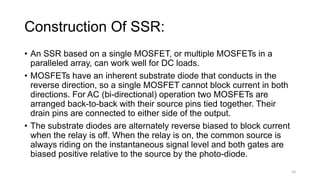
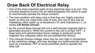
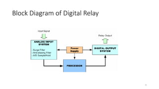
PRESENTATION
1) Electrical Relays
2) Mechanical Relays
3) Digital Relays
Presenting By
• Sheikh Rehan-Ul-Haq (Bset-01123101)
• Usama Umer (Bset-01133116)
• Mohammad Asif (Bset-01123116)
Relay:
Relays are switches that open and close circuits
electromechanically or electronically. Relays control
one electrical circuit by opening and closing contacts in another
circuit.
4
Electrical Relay:
Electrical Relays however, are basically electrically operated
switches that come in many shapes, sizes and power ratings
suitable for all types of applications. Relays can also have single
or multiple contacts within a single package with the larger power
relays used for mains voltage or high current switching
applications being called “Contactors”.
5
Classification Of Electrical Relays:
Electrical Relays are Classified into Two Types.
1) Electromechanical Relays.
In electromechanical relays (EMR), contacts
are opened or closed by a magnetic force.
2) Solid State Relays.
With solid state relay (SSR), there are no
contacts and switching is totally electronic.
* The decision to use electromechanical or solid state relays
depends on an application's electrical requirements, cost
constraints and life expectancy.
6
SSR:
• A solid-state relay (SSR) is an electronic switching device that
switches on or off when a small external voltage is applied
across its control terminals.
• SSRs consist of a sensor which responds to an appropriate
input (control signal), a solid-state electronic switching device
which switches power to the load circuitry, and a coupling
mechanism to enable the control signal to activate this switch
without mechanical parts.
• The relay may be designed to switch either AC or DC to the
load. It serves the same function as an electromechanical relay,
but has no moving parts
7
Working Of An SSR:
8
1) Packaged solid-state relays use
power semiconductor devices such
as thyristors and transistors, to switch currents up to around a
hundred amperes.
2) Solid-state relays have fast switching speeds compared
with electromechanical relays, and have no physical contacts
to wear out.
3) Application of solid-state relays must consider their lower
ability to withstand momentary overload, compared with
electromechanical contacts, and their higher "on" state
resistance.
9
4) Unlike an electromechanical relay, a solid-state relay provides
only limited switching arrangements.
Construction Of SSR:
• An SSR based on a single MOSFET, or multiple MOSFETs in a
paralleled array, can work well for DC loads.
• MOSFETs have an inherent substrate diode that conducts in the
reverse direction, so a single MOSFET cannot block current in both
directions. For AC (bi-directional) operation two MOSFETs are
arranged back-to-back with their source pins tied together. Their
drain pins are connected to either side of the output.
• The substrate diodes are alternately reverse biased to block current
when the relay is off. When the relay is on, the common source is
always riding on the instantaneous signal level and both gates are
biased positive relative to the source by the photo-diode.
10
11
• It is common to provide access to the common source so that
multiple MOSFETs can be wired in parallel if switching a DC
load.
• Usually a network is provided to speed the turn-off of the
MOSFET when the control input is removed.
• In AC circuits, SCR or TRIAC relays inherently switch off at the
points of zero load current. The circuit will never be interrupted
in the middle of a sine wave peak, preventing the large transient
voltages that would otherwise occur due to the sudden collapse
of the magnetic field around the inductance. This feature is
called zero-crossover switching
Advantages Over Mechanical Relay
• Slimmer profile, allowing tighter packing.
• Totally silent operation.
• SSRs switch faster than electromechanical relays; the switching time
of a typical optically coupled SSR is dependent on the time needed
to power the LED on and off - of the order of microseconds to
milliseconds.
• Increased lifetime, even if it is activated many times, as there are no
moving parts to wear and no contacts to pit or build up carbon.
• Output resistance remains constant regardless of amount of use.
12
• Clean, bounce less operation.
• No sparking, allows it to be used in explosive environments,
where it is critical that no spark is generated during switching.
• Inherently smaller than a mechanical relay of similar
specification (if desired may have the same "casing" form factor
for interchangeability).
• Much less sensitive to storage and operating environment
factors such as mechanical shock, vibration, humidity, and
external magnetic fields.
13
Disadvantages
• Voltage/current characteristic of semiconductor rather than
mechanical contacts.
• When closed, higher resistance (generating heat), and
increased electrical noise.
• When open, lower resistance, and reverse leakage
current (typically µA range).
• Voltage/current characteristic is not linear (not purely resistive),
distorting switched waveforms to some extent. An
electromechanical relay has the low ohmic (linear) resistance of
the associated mechanical switch when activated, and the
exceedingly high resistance of the air gap and insulating
materials when open. 14
• Some types have polarity-sensitive output circuits.
Electromechanical relays are not affected by polarity.
• Possibility of spurious switching due to voltage transients (due
to much faster switching than mechanical relay)
• Isolated bias supply required for gate charge circuit
• Higher transient reverse recovery time (Trr) due to the presence
of the body diode
• Tendency to fail "shorted" on their outputs, while
electromechanical relay contacts tend to fail "open".
15
Mechanical Relay:
Mechanical relays are devices that can turn on or turn off the
power supplied to another device, like a switch. However, instead
of having a person flip the switch, mechanical relays switch when
provided with a small amount of power. This allows high-power
circuits to be controlled by low-power devices.
16
17
Electromechanical Relay Construction:
• Frame: Heavy-duty frame that contains and supports the parts
of the relay.
• Coil: Wire is wound around a metal core. The coil of wire
causes an electromagnetic field.
• Armature: A relays moving part. The armature opens and
closes the contacts. An attached spring returns the armature to
its original position.
• Contacts: The conducting part of the switch that makes
(closes) or breaks (opens) a circuit.
18
Working Of Electromechanical Relay:
• As their name implies, electromechanical relays are electro-
magnetic devices that convert a magnetic flux generated by the
application of a low voltage electrical control signal either AC or
DC across the relay terminals, into a pulling mechanical force
which operates the electrical contacts within the relay.
• The armature is hinged or pivoted allowing it to freely move
within the generated magnetic field closing the electrical
contacts that are attached to it.
• Connected between the yoke and armature is normally a spring
(or springs) for the return stroke to “reset” the contacts back to
their initial rest position when the relay coil is in the “de-
energized” condition, i.e. turned “OFF”.
19
• Relays may be “Normally Open”, or “Normally Closed”. One pair
of contacts are classed as Normally Open, (NO) or make
contacts and another set which are classed as Normally
Closed, (NC) or break contacts.
• Normally Closed or Make and Break Contacts refer to the state
of the electrical contacts when the relay coil is “de-energized”
i.e. no supply voltage connected to the relay coil.
• The relays contacts are electrically conductive pieces of metal
which touch together completing a circuit and allow the circuit
current to flow, just like a switch.
• When the contacts are open the resistance between the
contacts is very high in the Mega-Ohms, producing an open
circuit condition and no circuit current flows.
20
• When the contacts are closed the contact resistance should be
zero, a short circuit, but this is not always the case. All relay
contacts have a certain amount of contact resistance when
they are closed and this is called the On-Resistance , similar to
FET’s.
• With a new relay and contacts this ON-resistance will be very
small, generally less than 0.2Ω’s because the tips are new and
clean, but over time the tip resistance will increase.
21
22
Electrical Relay Contact Tip Materials
• Ag (fine silver)
• 1. Electrical and thermal conductivity are the highest of all
the metals.
• 2. Exhibits low contact resistance, is inexpensive and widely
used.
• 3. Contacts tarnish easily through sulphurisation influence.
• AgCu (silver copper)
• 1. Known as “Hard silver” contacts and have better wear
resistance and less tendency to arc and weld, but slightly
higher contact resistance.
• AgCdO (silver cadmium oxide)
• 1. Very little tendency to arc and weld, good wear resistance
and arc extinguishing properties.
23
• AgW (silver tungsten)
• 1. Hardness and melting point are high, arc resistance is
excellent.
• 2. Not a precious metal.
• 3. High contact pressure is required to reduce resistance.
• 4. Contact resistance is relatively high & to corrosion is poor.
• AgNi (silver nickel)
• 1. Equals the electrical conductivity of silver, excellent arc
resistance.
• AgPd (silver palladium)
• 1. Low contact wear, greater hardness.
• 2. Expensive.
• Platinum, Gold and Silver Alloys
• 1. Excellent corrosion resistance, used mainly for low-current
circuits. 24
Electrical Relay Contact Configurations:
• SPST – Single Pole Single Throw
• SPDT – Single Pole Double Throw
• DPST – Double Pole Single Throw
• DPDT – Double Pole Double Throw
25
Electromechanical relays are also denoted by the combinations
of their contacts or switching elements and the number of
contacts combined within a single relay.
• A contact which is normally open in the de-energized position of the
relay is called a “Form A contact” or make contact.
• Whereas a contact which is normally closed in the de-energized
position of the relay is called a “Form B contact” or break contact.
• When both a make and a break set of contact elements are present
at the same time so that the two contacts are electrically connected
to produce a common point (identified by three connections), the set
of contacts are referred to as “Form C contacts” or change-over
contacts.
• If no electrical connection exists between the make and break
contacts it is referred to as a double change-over contact.
26
Draw Back Of Electrical Relay
• One of the more important parts of any electrical relay is its coil. This
converts electrical current into an electromagnetic flux which is used
to mechanically operate the relays contacts.
• The main problem with relay coils is that they are “highly inductive
loads” as they are made from coils of wire. Any coil of wire has an
impedance value made up of resistance ( R ) and inductance ( L ) in
series (LR Series Circuit).
• As the current flows through the coil a self induced magnetic field is
generated around it. When the current in the coil is turned “OFF”, a
large back emf (electromotive force) voltage is produced as the
magnetic flux collapses within the coil (transformer theory).
• This induced reverse voltage value may be very high in comparison
to the switching voltage, and may damage any semiconductor device
such as a transistor, FET or micro-controller used to operate the
relay coil.
27
Prevention
• One way of preventing damage to the transistor or any
switching semiconductor device, is to connect a reverse biased
diode like Free Wheeling Diode across the relay coil.
• When the current flowing through the coil is switched “OFF”, an
induced back emf is generated as the magnetic flux collapses in
coil.
• This reverse voltage forward biases the diode which conducts
and dissipates the stored energy preventing any damage to the
semiconductor transistor.
28
29
Digital Relay:
A digital protective relay is a computer-based system with
software-based protection algorithms for the detection of
electrical faults. Such relays are also termed as microprocessor
type protective relays.
Such relays are also termed as microprocessor type protective
relays. They are functional replacements for electro-
mechanical protective relays and may include many protection
functions in one unit
30
Block Diagram of Digital Relay
31
32
1. Microprocessor based relay
33
Types of Digital Relay
Input processing in Microprocessor
based relay
• Low voltage and low current signals (i.e., at the secondary of
a voltage transformers and current transformers) are brought
into a low pass filter that removes frequency content above
about 1/3 of the sampling frequency (a relay A/D
converter needs to sample faster than twice per cycle of the
highest frequency that it is to monitor). The AC signal is then
sampled by the relay's analog to digital converter from 4 to 64
(varies by relay) samples per power system cycle.
34
Logic processing in Microprocessor
based relay
The relay analyzes the resultant A/D converter outputs
to determine if action is required under its protection
algorithm(s). Protection algorithms are a set of logic
equations in part designed by the protection engineer,
and in part designed by the relay manufacturer. The
relay is capable of applying advanced logic.
35
Parameter setting Microprocessor
based relay
The logic is user-configurable and can vary from simply
changing front panel switches or moving of circuit
board jumpers to accessing the relay's internal
parameter setting webpage via communications link on
another computer hundreds of kilometres away.
36
Event recording Microprocessor
based relay
In some relays, a short history of the entire sampled
data is kept for oscillographic records. The event
recording would include some means for the user to see
the timing of key logic decisions, relay I/O (input/output)
changes, and see, in an oscillographic fashion, at least
the fundamental component of the incoming analogue
parameters.
37
Data display Microprocessor based
relay
Digital/numerical relays provide a front panel display, or
display on a terminal through a communication interface.
This is used to display relay settings and real-time
current/voltage values,
38
Advantages of Microprocessor based
Relay compare to Electromechanical
Relay
• The speed of operation is fast.
• Multifunctioning is possible.
• These relay have the directional feature.
• These relay can not suffer form the effects of age.
• These relay can be store previous data.
39
Disadvantages of Microprocessor
based Relay compare to
Electromechanical Relay
• The value can not be set easily. Special programming device is
required.
• They are not simple in construction.
40

Protection presentation

  • 2.
    PRESENTATION 1) Electrical Relays 2)Mechanical Relays 3) Digital Relays
  • 3.
    Presenting By • SheikhRehan-Ul-Haq (Bset-01123101) • Usama Umer (Bset-01133116) • Mohammad Asif (Bset-01123116)
  • 4.
    Relay: Relays are switchesthat open and close circuits electromechanically or electronically. Relays control one electrical circuit by opening and closing contacts in another circuit. 4
  • 5.
    Electrical Relay: Electrical Relayshowever, are basically electrically operated switches that come in many shapes, sizes and power ratings suitable for all types of applications. Relays can also have single or multiple contacts within a single package with the larger power relays used for mains voltage or high current switching applications being called “Contactors”. 5
  • 6.
    Classification Of ElectricalRelays: Electrical Relays are Classified into Two Types. 1) Electromechanical Relays. In electromechanical relays (EMR), contacts are opened or closed by a magnetic force. 2) Solid State Relays. With solid state relay (SSR), there are no contacts and switching is totally electronic. * The decision to use electromechanical or solid state relays depends on an application's electrical requirements, cost constraints and life expectancy. 6
  • 7.
    SSR: • A solid-staterelay (SSR) is an electronic switching device that switches on or off when a small external voltage is applied across its control terminals. • SSRs consist of a sensor which responds to an appropriate input (control signal), a solid-state electronic switching device which switches power to the load circuitry, and a coupling mechanism to enable the control signal to activate this switch without mechanical parts. • The relay may be designed to switch either AC or DC to the load. It serves the same function as an electromechanical relay, but has no moving parts 7
  • 8.
    Working Of AnSSR: 8 1) Packaged solid-state relays use power semiconductor devices such as thyristors and transistors, to switch currents up to around a hundred amperes. 2) Solid-state relays have fast switching speeds compared with electromechanical relays, and have no physical contacts to wear out. 3) Application of solid-state relays must consider their lower ability to withstand momentary overload, compared with electromechanical contacts, and their higher "on" state resistance.
  • 9.
    9 4) Unlike anelectromechanical relay, a solid-state relay provides only limited switching arrangements.
  • 10.
    Construction Of SSR: •An SSR based on a single MOSFET, or multiple MOSFETs in a paralleled array, can work well for DC loads. • MOSFETs have an inherent substrate diode that conducts in the reverse direction, so a single MOSFET cannot block current in both directions. For AC (bi-directional) operation two MOSFETs are arranged back-to-back with their source pins tied together. Their drain pins are connected to either side of the output. • The substrate diodes are alternately reverse biased to block current when the relay is off. When the relay is on, the common source is always riding on the instantaneous signal level and both gates are biased positive relative to the source by the photo-diode. 10
  • 11.
    11 • It iscommon to provide access to the common source so that multiple MOSFETs can be wired in parallel if switching a DC load. • Usually a network is provided to speed the turn-off of the MOSFET when the control input is removed. • In AC circuits, SCR or TRIAC relays inherently switch off at the points of zero load current. The circuit will never be interrupted in the middle of a sine wave peak, preventing the large transient voltages that would otherwise occur due to the sudden collapse of the magnetic field around the inductance. This feature is called zero-crossover switching
  • 12.
    Advantages Over MechanicalRelay • Slimmer profile, allowing tighter packing. • Totally silent operation. • SSRs switch faster than electromechanical relays; the switching time of a typical optically coupled SSR is dependent on the time needed to power the LED on and off - of the order of microseconds to milliseconds. • Increased lifetime, even if it is activated many times, as there are no moving parts to wear and no contacts to pit or build up carbon. • Output resistance remains constant regardless of amount of use. 12
  • 13.
    • Clean, bounceless operation. • No sparking, allows it to be used in explosive environments, where it is critical that no spark is generated during switching. • Inherently smaller than a mechanical relay of similar specification (if desired may have the same "casing" form factor for interchangeability). • Much less sensitive to storage and operating environment factors such as mechanical shock, vibration, humidity, and external magnetic fields. 13
  • 14.
    Disadvantages • Voltage/current characteristicof semiconductor rather than mechanical contacts. • When closed, higher resistance (generating heat), and increased electrical noise. • When open, lower resistance, and reverse leakage current (typically µA range). • Voltage/current characteristic is not linear (not purely resistive), distorting switched waveforms to some extent. An electromechanical relay has the low ohmic (linear) resistance of the associated mechanical switch when activated, and the exceedingly high resistance of the air gap and insulating materials when open. 14
  • 15.
    • Some typeshave polarity-sensitive output circuits. Electromechanical relays are not affected by polarity. • Possibility of spurious switching due to voltage transients (due to much faster switching than mechanical relay) • Isolated bias supply required for gate charge circuit • Higher transient reverse recovery time (Trr) due to the presence of the body diode • Tendency to fail "shorted" on their outputs, while electromechanical relay contacts tend to fail "open". 15
  • 16.
    Mechanical Relay: Mechanical relaysare devices that can turn on or turn off the power supplied to another device, like a switch. However, instead of having a person flip the switch, mechanical relays switch when provided with a small amount of power. This allows high-power circuits to be controlled by low-power devices. 16
  • 17.
    17 Electromechanical Relay Construction: •Frame: Heavy-duty frame that contains and supports the parts of the relay. • Coil: Wire is wound around a metal core. The coil of wire causes an electromagnetic field. • Armature: A relays moving part. The armature opens and closes the contacts. An attached spring returns the armature to its original position. • Contacts: The conducting part of the switch that makes (closes) or breaks (opens) a circuit.
  • 18.
  • 19.
    Working Of ElectromechanicalRelay: • As their name implies, electromechanical relays are electro- magnetic devices that convert a magnetic flux generated by the application of a low voltage electrical control signal either AC or DC across the relay terminals, into a pulling mechanical force which operates the electrical contacts within the relay. • The armature is hinged or pivoted allowing it to freely move within the generated magnetic field closing the electrical contacts that are attached to it. • Connected between the yoke and armature is normally a spring (or springs) for the return stroke to “reset” the contacts back to their initial rest position when the relay coil is in the “de- energized” condition, i.e. turned “OFF”. 19
  • 20.
    • Relays maybe “Normally Open”, or “Normally Closed”. One pair of contacts are classed as Normally Open, (NO) or make contacts and another set which are classed as Normally Closed, (NC) or break contacts. • Normally Closed or Make and Break Contacts refer to the state of the electrical contacts when the relay coil is “de-energized” i.e. no supply voltage connected to the relay coil. • The relays contacts are electrically conductive pieces of metal which touch together completing a circuit and allow the circuit current to flow, just like a switch. • When the contacts are open the resistance between the contacts is very high in the Mega-Ohms, producing an open circuit condition and no circuit current flows. 20
  • 21.
    • When thecontacts are closed the contact resistance should be zero, a short circuit, but this is not always the case. All relay contacts have a certain amount of contact resistance when they are closed and this is called the On-Resistance , similar to FET’s. • With a new relay and contacts this ON-resistance will be very small, generally less than 0.2Ω’s because the tips are new and clean, but over time the tip resistance will increase. 21
  • 22.
  • 23.
    Electrical Relay ContactTip Materials • Ag (fine silver) • 1. Electrical and thermal conductivity are the highest of all the metals. • 2. Exhibits low contact resistance, is inexpensive and widely used. • 3. Contacts tarnish easily through sulphurisation influence. • AgCu (silver copper) • 1. Known as “Hard silver” contacts and have better wear resistance and less tendency to arc and weld, but slightly higher contact resistance. • AgCdO (silver cadmium oxide) • 1. Very little tendency to arc and weld, good wear resistance and arc extinguishing properties. 23
  • 24.
    • AgW (silvertungsten) • 1. Hardness and melting point are high, arc resistance is excellent. • 2. Not a precious metal. • 3. High contact pressure is required to reduce resistance. • 4. Contact resistance is relatively high & to corrosion is poor. • AgNi (silver nickel) • 1. Equals the electrical conductivity of silver, excellent arc resistance. • AgPd (silver palladium) • 1. Low contact wear, greater hardness. • 2. Expensive. • Platinum, Gold and Silver Alloys • 1. Excellent corrosion resistance, used mainly for low-current circuits. 24
  • 25.
    Electrical Relay ContactConfigurations: • SPST – Single Pole Single Throw • SPDT – Single Pole Double Throw • DPST – Double Pole Single Throw • DPDT – Double Pole Double Throw 25
  • 26.
    Electromechanical relays arealso denoted by the combinations of their contacts or switching elements and the number of contacts combined within a single relay. • A contact which is normally open in the de-energized position of the relay is called a “Form A contact” or make contact. • Whereas a contact which is normally closed in the de-energized position of the relay is called a “Form B contact” or break contact. • When both a make and a break set of contact elements are present at the same time so that the two contacts are electrically connected to produce a common point (identified by three connections), the set of contacts are referred to as “Form C contacts” or change-over contacts. • If no electrical connection exists between the make and break contacts it is referred to as a double change-over contact. 26
  • 27.
    Draw Back OfElectrical Relay • One of the more important parts of any electrical relay is its coil. This converts electrical current into an electromagnetic flux which is used to mechanically operate the relays contacts. • The main problem with relay coils is that they are “highly inductive loads” as they are made from coils of wire. Any coil of wire has an impedance value made up of resistance ( R ) and inductance ( L ) in series (LR Series Circuit). • As the current flows through the coil a self induced magnetic field is generated around it. When the current in the coil is turned “OFF”, a large back emf (electromotive force) voltage is produced as the magnetic flux collapses within the coil (transformer theory). • This induced reverse voltage value may be very high in comparison to the switching voltage, and may damage any semiconductor device such as a transistor, FET or micro-controller used to operate the relay coil. 27
  • 28.
    Prevention • One wayof preventing damage to the transistor or any switching semiconductor device, is to connect a reverse biased diode like Free Wheeling Diode across the relay coil. • When the current flowing through the coil is switched “OFF”, an induced back emf is generated as the magnetic flux collapses in coil. • This reverse voltage forward biases the diode which conducts and dissipates the stored energy preventing any damage to the semiconductor transistor. 28
  • 29.
  • 30.
    Digital Relay: A digitalprotective relay is a computer-based system with software-based protection algorithms for the detection of electrical faults. Such relays are also termed as microprocessor type protective relays. Such relays are also termed as microprocessor type protective relays. They are functional replacements for electro- mechanical protective relays and may include many protection functions in one unit 30
  • 31.
    Block Diagram ofDigital Relay 31
  • 32.
  • 33.
    1. Microprocessor basedrelay 33 Types of Digital Relay
  • 34.
    Input processing inMicroprocessor based relay • Low voltage and low current signals (i.e., at the secondary of a voltage transformers and current transformers) are brought into a low pass filter that removes frequency content above about 1/3 of the sampling frequency (a relay A/D converter needs to sample faster than twice per cycle of the highest frequency that it is to monitor). The AC signal is then sampled by the relay's analog to digital converter from 4 to 64 (varies by relay) samples per power system cycle. 34
  • 35.
    Logic processing inMicroprocessor based relay The relay analyzes the resultant A/D converter outputs to determine if action is required under its protection algorithm(s). Protection algorithms are a set of logic equations in part designed by the protection engineer, and in part designed by the relay manufacturer. The relay is capable of applying advanced logic. 35
  • 36.
    Parameter setting Microprocessor basedrelay The logic is user-configurable and can vary from simply changing front panel switches or moving of circuit board jumpers to accessing the relay's internal parameter setting webpage via communications link on another computer hundreds of kilometres away. 36
  • 37.
    Event recording Microprocessor basedrelay In some relays, a short history of the entire sampled data is kept for oscillographic records. The event recording would include some means for the user to see the timing of key logic decisions, relay I/O (input/output) changes, and see, in an oscillographic fashion, at least the fundamental component of the incoming analogue parameters. 37
  • 38.
    Data display Microprocessorbased relay Digital/numerical relays provide a front panel display, or display on a terminal through a communication interface. This is used to display relay settings and real-time current/voltage values, 38
  • 39.
    Advantages of Microprocessorbased Relay compare to Electromechanical Relay • The speed of operation is fast. • Multifunctioning is possible. • These relay have the directional feature. • These relay can not suffer form the effects of age. • These relay can be store previous data. 39
  • 40.
    Disadvantages of Microprocessor basedRelay compare to Electromechanical Relay • The value can not be set easily. Special programming device is required. • They are not simple in construction. 40