SlideShare a Scribd company logo
International Research Journal of Engineering and Technology (IRJET) e-ISSN: 2395-0056
Volume: 09 Issue: 04 | Apr 2022 www.irjet.net p-ISSN: 2395-0072
© 2022, IRJET | Impact Factor value: 7.529 | ISO 9001:2008 Certified Journal | Page 3827
Regenerative Braking in Indian Locomotives: A model involving the
use of flywheel as an ESD (Energy Storage Device) in WAP-7
Locomotives
Subhadeep Kuila1, Sudhanshu Yadav2
1 School of Engineering and Applied Sciences, National Rail & Transportation Institute, Vadodara
2School of Engineering and Applied Sciences, National Rail & Transportation Institute, Vadodara
---------------------------------------------------------------------***---------------------------------------------------------------------
Abstract - A new mathematical model to estimate the
regenerative braking efficiency of Indian locomotives, which
are already installed with the 'regenerative brakingsystem,'is
discussed here. It is demonstratedforaWAP-7locomotivethat
runs on Indian tracks. This paper discusses the need of having
an alternate energy recovery mechanism, (Flywheel here) in
the mechanical model of the locomotive. The effectofgradient
on energy savings for this new model is discussed here. The
drive cycle relationships have been developed to study energy
estimations on the selectedrouteofADI-MMCT. Finally, energy
savings of the model proposed is compared with the energy
savings of the already existing mechanism of WAP-7.
Key Words: Flywheel, FBESS, Mathematical Model,
Regenerative Braking, OBESS
1. INTRODUCTION
One of the environmentally friendly ways of
transportation is railways. It is a critical approach to meet
rising transportationdemandsinanecologicallyconscious
economy. India's rail sector remains a large energy user.
With a growing population and greater energy
consumption, the need for rail services will continue to
rise, and energy consumption will increase in tandem.1
The energy lost as trains reach rail stations provides an
obvious additional source of energy that may be used to
reduce demands on electricity production facilities and
improve the overall efficiency of the electrical grid in large
metropolitan regions. The energy lost as trains reach rail
stations provides anobvious additional sourceofenergythat
may be used to reduce demands on electricity production
facilities and improve the overall efficiency of the electrical
grid in large metropolitan regions. The quantity of energy
wasted every day in our civilization is startling. The causes
vary from inefficient systems like single-pane windows in
homes to vital but inelegant systems like friction brakes on
nearly every mode of transportation.
The theory of regenerative braking captures the energy
expended when cars use their brakes to slow down, and it
provides a practical way to use otherwise dissipatedenergy.
Using lost energy to boost energy supply to the electrical
grid without incurring additional production expenses can
improve the electrical grid'soverall efficiency.Theotherwise
squandered braking power may be effectively and cheaply
gathered and utilized to replenish the neighbouring
electrical grid by using electrical generators positioned on
train rails at appropriate locations to provide the
deceleration forces necessary for braking.
1.1. CURRENT SCENARIO OF REGENERATIVE
BRAKING IN INDIAN RAILWAYS
The Indian Railways have been particularly attentive
about energy conservation and efficient utilization. Electric
traction has a unique function called 'regenerative braking,'
which converts the train's energy in motion to electric
energy upon braking and giving it back to the feeder
services. This function has beensuccessfullyimplemented in
the WAG-9, WAP-7, and WAP-5locomotiveclasses,savingup
to 20% and on all new electrical multiple units (EMU) that
can save up to 30%. While this function saves energy, it also
extends the life of the wheels andenhancestheLocomotive's
availability for driving trains, making electric traction more
cost-effective.3
Figure 1: The regeneration values of 3-Phase electric
rolling stock of Indian Railways
The figure above depicts the regeneration and traction
values of 3-Phase electric rolling stock used by Indian
Railways in WAG-9, WAP-5, WAP-7, and EMUs (Electric
Multiple Units). It could be seen that the regeneration
capabilities of EMUs are more significant than the rest of the
categories mentioned. While it is very appreciable to note
that Indian Railways has successfully achieved a
regeneration saving of above 20% on the locomotiveclasses
of WAG-9 and WAP-5, it is also crucial to increase
regeneration efficiency in these areas classes of locomotives
to compensate for energy losses. 3
Railways have reduced Specific Energy Consumption (SEC)
by roughly 18.9% during the previous five years through
different energy conservation strategies. According to the
BEE evaluation for 2014-2015, energy usage in traction
applications improved by 3.3 per cent from a year earlier.
International Research Journal of Engineering and Technology (IRJET) e-ISSN: 2395-0056
Volume: 09 Issue: 04 | Apr 2022 www.irjet.net p-ISSN: 2395-0072
© 2022, IRJET | Impact Factor value: 7.529 | ISO 9001:2008 Certified Journal | Page 3828
Over several years, Indian Railways has also received 87
energy conservation awards.
1.2 COMPARATIVE ANALYSIS OF REGENERATIVE
BRAKING ENERGY SAVINGS: CASE OF INDIAN
RAILWAYS NCR & UNITED KINGDOM SWR
We have tried to compare the case of Indian
Railways' North-Central Region and United Kingdom's
South-West Region running trains with Regenerative
Braking capabilities to conclude with what measure Indian
Railways should rely upon for achievingan excellentenergy-
saving index.
NCR has saved over 15 million power units by running
these trains with three-phaseinductiontractionmotors with
regeneration capabilities.4 Cutting down to numbers, we
have 400 electric locomotives running across NCR, out of
which 100 have regenerative capabilities, and the15million
kWh saving of electricity is due to these 100 three-phase
induction traction motors fitted locomotives only.
More than 200 electric trains on the South-West Trains
network have had equipment installedaspartofthescheme.
These trains serve Guildford, Alton, Portsmouth, Reading,
Southampton, and Weymouth in the London suburbs.
They've all been upgraded to include the new energy-saving
technologies. The technique saves 50 million kWh of
electricity each year, enough to power around 11,500 UK
households for a year.5
We could conclude, from the figures below that despite
having double the number of trains equipped with
Regeneration capabilities, the energy saving is almost 3.5
times that of the NCR region. The track on which these
figures have been taken has approximately the same track
length, which Trains running in SWR Class 458 Class 444
Figure 3: Proportion of 3-Phase ITM locomotives from NCR
makes the comparison fair enough to decide what extra
technologies UK's SWR uses that make it such energy
efficient. We will be talking about that part in later sections
of our paper.
1.3 MODERN ELECTRIC RAIL VEHICLE: OVERVIEW
& POWER FLOW IN WAP-7 LOCOMOTIVE
WAP-7 is the 7th generation of WAP class locomotives,
where W stands for broad gauge (Wide), A stands for AC
Electric locomotive, and P for Passenger locomotive. WAG-9
is the 9th generation of WAG class locomotives, where W
stands for the same broad gauge (Wide), A stands for AC
Electric locomotive, and G for Goods or freight locomotive.
The major components of this WAP-7 locomotive are a)
Pantograph, which collects the high tension current (25 kV)
from the contact wire, b) Voltage Regulating Equipment,
where the main transformer, consistsofanAutotransformer
with 32 taps and a stepped-down transformer with two
distinct secondary windings, steps down the high OHE
voltage to a low voltage, c)Silicon Rectifiers, which converts
the alternating current provided by secondary windings of
the main transformer is into direct current utilizing two
silicon rectifiers (RSI), one each supplying to set off three
traction motors, d)Traction Induction Motor, which is the
prime mover of the locomotive. Generally, a three-phase
Induction motor is used as the primarytractionmotordue to
its Electromagnetic properties.6
Figure 2: Main Components of a Modern Electric Rail
Vehicle
The power flow through the locomotive happens wherein,
the "traction sub-station," a single-phase step-down
transformer is linked to the three-phase utility system,
which feeds energy to the overhead line (high-voltage) and
the rail ("ground"). The pantograph captures the AC power
and is then provided to the vehicle. The Locomotive is fitted
with appropriate equipment to enable the loco pilot to
manage the train's speed according to requirements by
regulating the applied voltage to traction motors. The 25KV,
single-phase AC power is gathered from the OHE by a roof-
mounted pantograph and stepped down by a transformerin
typical locomotives. Before being supplied to the traction
motors, this supply is converted to DC using a full-wave
silicon rectifier and related smoothing filter.Thevariationof
the AC input voltage to the rectifier via an on-load tap
changing arrangement on the primary winding of the
locomotive transformer is used to manage torque and
speed.7
Figure 3: Simplified view of power flow in a WAP-7
locomotive
The Locomotive'sprimarytransformerstepsdownthe25 kV
overhead AC supply. It feeds it to a front end (line) dual 4-
quadrant line converter, which converts the AC to DC using
Pulse Width Modulation (PWM) to achieve a unity power
factor. This supply is connected to an input side converter
through a DC connection, which serves as an energy
reservoir. The VVVF Converter transforms the DC supply
International Research Journal of Engineering and Technology (IRJET) e-ISSN: 2395-0056
Volume: 09 Issue: 04 | Apr 2022 www.irjet.net p-ISSN: 2395-0072
© 2022, IRJET | Impact Factor value: 7.529 | ISO 9001:2008 Certified Journal | Page 3829
into three phases, subsequently delivered to three-phase
traction motors. The output of theDriveconverter(inverter)
is a VVVF (Variable Voltage Variable Frequency) supply,
which aids in adjusting the starting and operatingtorquesof
three-phase traction motors to meet traffic needs.
1.4 BRAKING OF A WAP-7 LOCOMOTIVE
In traction systems, there are two forms of braking:dynamic
(electric) braking and classic friction braking. The produced
current is used for regenerative braking when a traction
motor is transferred toa generatorfordynamic braking. This
braking is helpful for heavy-haul diesel electric locomotives
operating on routes with significant downgrades. When
regenerative braking is used to decelerate the train, the
current in the electric motors is reversed.8
In a Conventional Friction Brake, the hydraulic
mechanism mainly drives the braking system.Itconsistsofa
primary, or master, cylinder filled with fluid and linked to a
secondary or slave cylinder. When the brake pedal is
depressed, a piston in the master cylinder depresses,forcing
fluid through the circuit and into the slave cylinders at each
wheel, which push the pistons to apply the brakes
effectively. This system has improved over time with
advancements like disc brakes, floating and multi-piston
callipers, and power brakes, making braking more effective
and comfortable for the driver, particularly with today's
engines' more significant power outputs.9
Figure 4: Conventional Friction Braking of a WAP-7
locomotive
Let us now look at the regenerative energy recovery
mechanism used in Locomotive and the subsequent energy
usage utilized by an accelerating train on the same contact
line. It could be seen that the energy recovered by one train
is sent back to the OHE line for other accelerating trains to
feed upon it.
Figure 5: Block diagram of energy recovery and usage on
same OHE line by an accelerating train
In Regenerative Braking of a WAP-7 locomotive, if we get
energy back from the Traction motor, it acts as a generator,
generating electrical energy from the kinetic energy when
braked upon. So, in the case of regenerative braking, and
Induction Motor acts as an Induction Generator. Induction
Motor acts as an Induction generator when the slip becomes
negative, i.e., when the slip of motor is less than 0, then kicks
in the regenerative braking capability of the motor, and
when the slip is greater than 0. The motor tractioncapability
acts upon the device.
S R
S
N N
slip
N


NS is synchronous speed and NR is speed of rotor
In easy words:
Slip>0, NS>NR: Induction Motor
Slip<0, NS<NR: Induction Generator
When the brakes are applied, the NS is reduced to such a
level that the value of NS is less than the NR. Thus, the motor
acts as a generator, generating electricity from the
mechanical shaft movement due to inertia. NS could be
altered as it depends upon the frequency of the Alternating
Current supplied to the motor. The slip could be changed
when braking is needed to make it less than 0. 10
By reducing the frequency of AC supply, we could
suddenly reduce the NS or synchronous speed,butNRorthe
rotor speed would not reduce suddenly due to the inertia it
has gained by rotating. This is how the NS or the slip is
changed for making the motor behaveasa generator. Weuse
Variable Frequency Drives (VFD) to change the frequencyof
the AC being provided to the motor. A variable frequency
drive (VFD) is a motor controller that controlsthefrequency
and voltage of an electric motor's power supply.
As soon as the slip becomes negative, the motor's torque
also becomes negative, i.e., it reverses the direction of
applied torque. The torque of the motor tries to adjust itself
by changing from negative to positive, but when the value of
torque in its quest of becoming positive touches the value of
0, i.e., zero torque, the supply of current is cut down to the
motor, which forces the motor to stop. We receive excess
energy as an energy-saving from this regeneration
mechanism. The same could be understood from the graph
given below-
Figure 6: Torque and Speed Characteristics of an Induction
motor
International Research Journal of Engineering and Technology (IRJET) e-ISSN: 2395-0056
Volume: 09 Issue: 04 | Apr 2022 www.irjet.net p-ISSN: 2395-0072
© 2022, IRJET | Impact Factor value: 7.529 | ISO 9001:2008 Certified Journal | Page 3830
2. MATHEMATICAL MODELING OFWAP-7TRAINS
The mathematical model for WAP7 locomotive developed in
this research uses the equations ofmotion.Thetractiveeffort
Ftrac., track resistance force Tres, and the gradient force Tgrad
are considered as the three main operating force on the
train’s body.
− − = · a= (1)
Meff is the effective mass of the train, Fa is the net resultant
force accelerating the train.
2.1. Equations governing train dynamics
The motion of train is majorly governed by the newtons
third law of motion. The effective mass of the train is
dependent upon the mass of locomotives, tare mass of the
carriages and the mass of the payload.
(2)
Here, Mloco is the mass of the locomotive, Ncarr Is the total
number if the carriages, Mtare is the tare mass of the carriage
and Mpayload is payload per vehicle. By using (1) and (2) we
can find the acceleration as:
(3)
Tractive effort is the net force applied by the locomotive
parallel to the direction of motion. The tractive effort is
constrained by the motor current limits and the mechanical
restriction. Values of the starting effort, continuous traction
effort and braking effort is taken from the official
documentation. A train's track resistance is its velocity-
dependent resistance to motion. The semi-empirical Davis
equation is commonly used to calculate resistance.
= + + (4)
DA ,DB ,DC are the coefficients for the various frictional force.
Effect of gradient with θ as track gradient calculated as:
(5)
2.2. Train Parameters
The focus of our study is the WAP 7 locomotive, for that we
have chosen Shatabdi Express through the route ADI-MMCT
(Ahmedabad Jn – Mumbai Central) would be used. This
convoy is chosen because it is one of the fastest convoys on
one of the busiest sections. The data used is given in the
table below.
Table 1 – Data for WAP 7 and Shatabdi Convoy
2.3. Drive Cycle and Energy Estimation
A driving cycle is necessary to evaluate the train's energy
consumption because the efficiencyofahybridpowertrainis
highly dependent on the duty cycle as well as route
parameters. We used the data available on the Ahmedabad-
Mumbai route of Shatabdi express for recreating the driving
cycle in simulation. The recreated driving cycle's distances
and time were tested and validated against figures given by
erail.in. Table (2) below shows the input used for the driving
cycle, which should be read from left to right.
Sr
no.
Station waitin
g time
(sec)
Trave
l Time
(sec)
Distance
(m)
1 Ahmedaba
d
0 2040 45000
2 Nadiad 120 1020 19000
3 Anand 120 1800 35000
4 Vadodara 300 2820 71000
5 Bharuch 120 2760 58000
6 Surat 300 3840 93000
7 Vapi 120 5220 140000
8 Borivali 180 3420 30000
9 MMCT 0
Table 2 – Route data for drive cycle
The track's gradient data is not given, but the model can
handle gradients, allowing broad dependencies on uniform
gradients to be demonstrated.
Based on a modified version of the velocity-step approach
(Ref. Jong J-C, Chang S), driving cycle is created. The driving
cycle is set up to correspond to the distance and time
requirements listed in data table provided above. The
approach is modified by introducing a constant velocity part
in the simulation that helps in meeting the timeframefor the
given distance. There are three phases to each driving
section: acceleration, constant velocity motion, and
deceleration as depicted in the figure given below. The
acceleration (section a), constant speed (section b) and
deceleration trajectory (section c).
International Research Journal of Engineering and Technology (IRJET) e-ISSN: 2395-0056
Volume: 09 Issue: 04 | Apr 2022 www.irjet.net p-ISSN: 2395-0072
© 2022, IRJET | Impact Factor value: 7.529 | ISO 9001:2008 Certified Journal | Page 3831
Figure 7: Drive cycle, showing the three sections
Accelerationstartsat each stationand establishes a constant
speed, while the deceleration trajectory (section c) is
dependent upon, thenextarrivingstation,brakingpowerand
safety and comfort restrictions. Distance covered in all the
three phases are computed concurrently as the velocity is
increased in each step in an iterative manner. As the net
distance travelled (area under the velocity time curve)
matches or exceeds the driving length of thegivensectionwe
stop the acceleration. Then the train travels at a constant
speed for a pre decided length, and then starts to
deaccelerateas it reaches the calculated braking distance.As
a result, the time criteria are met precisely, whereas the
distances are near accurate.
After using equation 3 for determining acceleration, we
moved on to determining velocity, formula used for that is.
(6)
The distance covered was updated using following
equation.
(7)
The data vital to this simulation is the power consumption
throughout the journey. The instantaneous tractive power
required by the train is determined by:
(8)
The energy consumption and energy recovered by the
regenerative braking are what we're interested in. The
following is the formula for energy.
(9)
The energy consumption during the traction will be
calculated by using:
(10)
The energy recovered during the braking of train will be
calculated using:
(11)
2.4. Implementation
In Python, numerical model incorporating all the equations
discussed above was created.Drivingcycleiscomputedafter
taking in the input of route profile, train parameters and
other constraints. The velocity-step algorithm is applied at
every section of track. Continuouscomputationisperformed
to calculate the distance traveled and braking distance
required. For each velocity step, it starts with calculatingthe
force required to overcome the force of friction and other
resistances. Then it moves onto calculate the resultant
acceleration using the equation (3) provided above. Further
it updates the velocity and acceleration using equations 6
and 7. Next it checks the braking distance and braking time
required to stop this train, after this the time for which the
train will run at a constant speed is calculated. The distance
travelled in all three (accelerating, constant speed, braking)
phases is added up. This process is repeated until the sum of
distances meet the prescribed distance of the section. After
generating the drive cycle all time-dependent kinematic
variables and forces are calculated, and the energy
consumption is evaluated during postprocessing using the
equations 10 and 11.
Below is the flow chart depicting the outline of the whole
process implemented to obtain results.
Figure 8: Basic modules and steps used in Python
modelling
3. RESULTS
Below are the results and graphs obtained from the
simulation. This simulation estimates the total energy
consumed by the train in traction, we can use this to
compute the energy taken from substation using equation
12.
(12)
Here E_trac^Ac is the total energy takenfromthesubstation,
E_trac^ is the traction energy obtained from equation 10.
η_1 is the induction motor’s efficiency to convert the input
electrical energy to output traction energy. Similarly,
simulation also produces the cumulative braking energy
produced during drive cycles.
We can use this to obtain the net amount of energy arriving
at the flywheel by using equation (13).
(13)
International Research Journal of Engineering and Technology (IRJET) e-ISSN: 2395-0056
Volume: 09 Issue: 04 | Apr 2022 www.irjet.net p-ISSN: 2395-0072
© 2022, IRJET | Impact Factor value: 7.529 | ISO 9001:2008 Certified Journal | Page 3832
Recovered energy is equal to the multiplication of energy
stored in flywheel with flywheel’s efficiency.
(14)
In the equation (13) is the energy reaching the
flywheel energy storage system (FESS). Multiplied with
efficiency of the FESS we obtain that is the
energy stored in the FESS. Since the energy must again pass
through the induction motor to reach the wheelsofthetrain,
the energy recovered is equal to the energy collected by the
FESS multiplied by .
(15)
We also obtain the value of efficiency gain, which is defined
as the ratio of energy recovered to the ratio of energy spent
through-out the trip (16). As well as the value of energy
recovery efficiency which is defined as the ratio of energy
recovered to braking energy (17).
(16)
(17)
3.1. Results for zero gradient
Graphs below of passenger stock (18 LHB II Ac Coaches)
being pulled by the WAP 7 locomotive on the route shownin
table 1.
Velocity-Time Curve
The maximum velocity attained 28.72 m/s.
Acceleration-Time curve
Peak acceleration for this run is 0.31m/s2, peak
deacceleration is 0.051m/s2.
Power-Time curve
Peak accelerationpowerforthisrunis4.79Megawatts,
peak power during deacceleration is -1.54 Megawatts.
Traction Energy-Time curve
Total consumption of energy in whole travel time is
4.65×10⁹ watt-hrs.
Braking Energy-Time curve
Total consumption of energy while braking is 2.304*109
watt-hrs.
Table below shows the various combinations of passenger
stock being pulled by the WAP 7 locomotive on the route
shown in table 1. The value for the efficiency of induction
motor is taken as 0.88, and the efficiency of Flywheel
as 0.90.
International Research Journal of Engineering and Technology (IRJET) e-ISSN: 2395-0056
Volume: 09 Issue: 04 | Apr 2022 www.irjet.net p-ISSN: 2395-0072
© 2022, IRJET | Impact Factor value: 7.529 | ISO 9001:2008 Certified Journal | Page 3833
Table 3: Estimated recovered energy for various train
configurations on route shown in table 1
For a train consisting of 18 fully loaded LHB II AC coaches
the total energy spent in traction is 5.29×10^6 kWh. The
braking energy generated is 2.304×10^6 kWh. Total energy
that can be recovered if on-board FESS is used 1.6×10^6
kWh, which is around 30% of total energy supplied for the
traction. Similarly, for all other composition of the stock
value of ε ranges from 0.29 to 0.31. Whereas the value of ϵ is
constant for all the compositions.
Figure 9: Comparison of trains running with and without
FESS
Total energy consumed over the trip represented by orange
curve is 4.65×10^6 kWh and for the blue curveis2.36×10^6
kWh. Estimated energy savings by using FESS in this case is
2.29×10^6 kWh.
4. CONCLUSIONS
The results show that utilizing the FESS can save a
significant amount of energy. The estimated energy savings
varied depending on the track, payload, number of cars per
train, and kind of FESS. The net recovered energy ranges
from 29-31% of the total energy consumed. With increasing
gradient, the energy savings from a flywheel decreased due
to less requirement of braking on up-terrain.
The feasibility of a FESS for decreasing energy usage in
passenger rail transportation systems is confirmed in this
study. The technique and resultscanbeapplicabletovarious
rail routes, even if the results were achieved for a specific
route.
5. REFERENCES
[1] Douglas, H.; Roberts, C.; Hillmansen, S.; Schmid, F. An
assessment of available measures to reduce traction energy
use in railway networks. Energy Conv. Manag. 2015, 106,
1149–1165, Available at:
http://dx.doi.org/10.1016/j.enconman.2015.10.053
[2] Asegid Belay Kebede, Getachew Biru Worku, A research
on regenerative braking energy recovery: A case of Addis
Ababa light rail transit, Science Direct, 2021, Available at:
https://www.sciencedirect.com/science/article/pii/S25901
16821000151
[3] Energy Scenario, RAILWAYS SYSTEM FOR ANALYSIS OF
VIDYUT ENERGY, [online], no date, Available at:
https://www.railsaver.gov.in/en_scenario.html
[4] Ashraf Jamal, 'Regenerative braking helps Railways to
save energy, money, Times of India, 26 September 2011
[online], Available at:
https://timesofindia.indiatimes.com/city/allahabad/regene
rative-braking-helps-railways-to-save-energy-
money/articleshow/10131180.cm
[5] South-West trains complete £2.2M investment in
Regenerative Braking system to drive greener trains, News
Releases, Stagecoach, 29 March 2012 [online]
[6] M Tulbure, R Both, Models for AC locomotive
Regenerative Braking, IEEE Xplore, [online], no date
[7] How Electric Locomotives (Electric Trains) Work,
StudyElectrical, 2019, [online]
[8] Vlad Radu, Understanding Conventional Friction Brakes
and the Regenerative Braking System, Autoevolution, 4
October 2020,
https://www.autoevolution.com/news/understanding-
conventional-friction-brakes-and-the-regenerative-braking-
system-149614.htm
[9] Regenerative Braking of Induction Motor, Electrical
Yatra, [Blog], no date
[10] Regenerative Braking of 3 Phase Induction Motor,
Lecture 28, Electrical Yatra, 18 September 2018

More Related Content

Similar to Regenerative Braking in Indian Locomotives: A model involving the use of flywheel as an ESD (Energy Storage Device) in WAP-7 Locomotives

EVOLUTION OF ELECTRIC CARS
EVOLUTION OF ELECTRIC CARSEVOLUTION OF ELECTRIC CARS
EVOLUTION OF ELECTRIC CARSIRJET Journal
 
Energy Management System in Electric Vehicle with PV Fed SRM System
Energy Management System in Electric Vehicle with PV Fed SRM SystemEnergy Management System in Electric Vehicle with PV Fed SRM System
Energy Management System in Electric Vehicle with PV Fed SRM SystemIJMTST Journal
 
Free Powered Electric Vehicle_Designed by Pranav Navathe
Free Powered Electric Vehicle_Designed by Pranav NavatheFree Powered Electric Vehicle_Designed by Pranav Navathe
Free Powered Electric Vehicle_Designed by Pranav NavathePranavNavathe
 
Efficient Utilisation of Regenerative Braking in Railway Operations
Efficient Utilisation of Regenerative Braking in Railway OperationsEfficient Utilisation of Regenerative Braking in Railway Operations
Efficient Utilisation of Regenerative Braking in Railway OperationsIRJET Journal
 
IRJET - Dynamic Wireless Electric Vehicle Charging System for Safe and Pr...
IRJET -  	  Dynamic Wireless Electric Vehicle Charging System for Safe and Pr...IRJET -  	  Dynamic Wireless Electric Vehicle Charging System for Safe and Pr...
IRJET - Dynamic Wireless Electric Vehicle Charging System for Safe and Pr...IRJET Journal
 
Grid to vehicle concept
Grid to vehicle conceptGrid to vehicle concept
Grid to vehicle conceptIhave4
 
Hybrid vehicle drivetrains- My published manuscript in International Research...
Hybrid vehicle drivetrains- My published manuscript in International Research...Hybrid vehicle drivetrains- My published manuscript in International Research...
Hybrid vehicle drivetrains- My published manuscript in International Research...ZelieusNamirian
 
ELECTRICITY GENERATION USING RAILWAY TRACK
ELECTRICITY GENERATION USING RAILWAY TRACKELECTRICITY GENERATION USING RAILWAY TRACK
ELECTRICITY GENERATION USING RAILWAY TRACKIRJET Journal
 
A Comprehensive Review of Electric Vehicle Charging Station Topologies
A Comprehensive Review of Electric Vehicle Charging Station TopologiesA Comprehensive Review of Electric Vehicle Charging Station Topologies
A Comprehensive Review of Electric Vehicle Charging Station TopologiesIRJET Journal
 
Development of Battery Management System for Maximizing Battery Performance i...
Development of Battery Management System for Maximizing Battery Performance i...Development of Battery Management System for Maximizing Battery Performance i...
Development of Battery Management System for Maximizing Battery Performance i...IRJET Journal
 
Three Receiver Coil System for Dynamic Wireless EV Charging Dynamic Charging ...
Three Receiver Coil System for Dynamic Wireless EV Charging Dynamic Charging ...Three Receiver Coil System for Dynamic Wireless EV Charging Dynamic Charging ...
Three Receiver Coil System for Dynamic Wireless EV Charging Dynamic Charging ...IRJET Journal
 
IRJET- Enhancement in the Modelling of Braking System with Regenerative Metho...
IRJET- Enhancement in the Modelling of Braking System with Regenerative Metho...IRJET- Enhancement in the Modelling of Braking System with Regenerative Metho...
IRJET- Enhancement in the Modelling of Braking System with Regenerative Metho...IRJET Journal
 
Analysis for Size of Ultra-Capacitor Bank to be Installed on 1.5kV System for...
Analysis for Size of Ultra-Capacitor Bank to be Installed on 1.5kV System for...Analysis for Size of Ultra-Capacitor Bank to be Installed on 1.5kV System for...
Analysis for Size of Ultra-Capacitor Bank to be Installed on 1.5kV System for...IOSR Journals
 
DYNAMIC CHARGING OF ELECTRIC VEHICLES
DYNAMIC CHARGING OF ELECTRIC VEHICLESDYNAMIC CHARGING OF ELECTRIC VEHICLES
DYNAMIC CHARGING OF ELECTRIC VEHICLESIRJET Journal
 
FABRICATION AND ANALYSIS OF SELF CHARGING ELECTRIC CAR
FABRICATION AND ANALYSIS OF SELF CHARGING ELECTRIC CARFABRICATION AND ANALYSIS OF SELF CHARGING ELECTRIC CAR
FABRICATION AND ANALYSIS OF SELF CHARGING ELECTRIC CARIRJET Journal
 
Simulation studies on developed Solar PV Array based Multipurpose EV Charger ...
Simulation studies on developed Solar PV Array based Multipurpose EV Charger ...Simulation studies on developed Solar PV Array based Multipurpose EV Charger ...
Simulation studies on developed Solar PV Array based Multipurpose EV Charger ...IRJET Journal
 
Optimal design and static simulation of a hybrid solar vehicle
Optimal design and static simulation of a hybrid solar vehicleOptimal design and static simulation of a hybrid solar vehicle
Optimal design and static simulation of a hybrid solar vehicleIRJASH
 
Review on Enhanced EV technology: Wireless charging system and performance im...
Review on Enhanced EV technology: Wireless charging system and performance im...Review on Enhanced EV technology: Wireless charging system and performance im...
Review on Enhanced EV technology: Wireless charging system and performance im...IRJET Journal
 
DESIGN & DEVELOPMENT OF MECHANICAL VARIABLE TRANSMISSION SYSTEM WITH HIGH STA...
DESIGN & DEVELOPMENT OF MECHANICAL VARIABLE TRANSMISSION SYSTEM WITH HIGH STA...DESIGN & DEVELOPMENT OF MECHANICAL VARIABLE TRANSMISSION SYSTEM WITH HIGH STA...
DESIGN & DEVELOPMENT OF MECHANICAL VARIABLE TRANSMISSION SYSTEM WITH HIGH STA...IRJET Journal
 

Similar to Regenerative Braking in Indian Locomotives: A model involving the use of flywheel as an ESD (Energy Storage Device) in WAP-7 Locomotives (20)

EVOLUTION OF ELECTRIC CARS
EVOLUTION OF ELECTRIC CARSEVOLUTION OF ELECTRIC CARS
EVOLUTION OF ELECTRIC CARS
 
Energy Management System in Electric Vehicle with PV Fed SRM System
Energy Management System in Electric Vehicle with PV Fed SRM SystemEnergy Management System in Electric Vehicle with PV Fed SRM System
Energy Management System in Electric Vehicle with PV Fed SRM System
 
Free Powered Electric Vehicle_Designed by Pranav Navathe
Free Powered Electric Vehicle_Designed by Pranav NavatheFree Powered Electric Vehicle_Designed by Pranav Navathe
Free Powered Electric Vehicle_Designed by Pranav Navathe
 
Efficient Utilisation of Regenerative Braking in Railway Operations
Efficient Utilisation of Regenerative Braking in Railway OperationsEfficient Utilisation of Regenerative Braking in Railway Operations
Efficient Utilisation of Regenerative Braking in Railway Operations
 
IRJET - Dynamic Wireless Electric Vehicle Charging System for Safe and Pr...
IRJET -  	  Dynamic Wireless Electric Vehicle Charging System for Safe and Pr...IRJET -  	  Dynamic Wireless Electric Vehicle Charging System for Safe and Pr...
IRJET - Dynamic Wireless Electric Vehicle Charging System for Safe and Pr...
 
Grid to vehicle concept
Grid to vehicle conceptGrid to vehicle concept
Grid to vehicle concept
 
Hybrid vehicle drivetrains- My published manuscript in International Research...
Hybrid vehicle drivetrains- My published manuscript in International Research...Hybrid vehicle drivetrains- My published manuscript in International Research...
Hybrid vehicle drivetrains- My published manuscript in International Research...
 
ELECTRICITY GENERATION USING RAILWAY TRACK
ELECTRICITY GENERATION USING RAILWAY TRACKELECTRICITY GENERATION USING RAILWAY TRACK
ELECTRICITY GENERATION USING RAILWAY TRACK
 
A Comprehensive Review of Electric Vehicle Charging Station Topologies
A Comprehensive Review of Electric Vehicle Charging Station TopologiesA Comprehensive Review of Electric Vehicle Charging Station Topologies
A Comprehensive Review of Electric Vehicle Charging Station Topologies
 
Development of Battery Management System for Maximizing Battery Performance i...
Development of Battery Management System for Maximizing Battery Performance i...Development of Battery Management System for Maximizing Battery Performance i...
Development of Battery Management System for Maximizing Battery Performance i...
 
H045045059
H045045059H045045059
H045045059
 
Three Receiver Coil System for Dynamic Wireless EV Charging Dynamic Charging ...
Three Receiver Coil System for Dynamic Wireless EV Charging Dynamic Charging ...Three Receiver Coil System for Dynamic Wireless EV Charging Dynamic Charging ...
Three Receiver Coil System for Dynamic Wireless EV Charging Dynamic Charging ...
 
IRJET- Enhancement in the Modelling of Braking System with Regenerative Metho...
IRJET- Enhancement in the Modelling of Braking System with Regenerative Metho...IRJET- Enhancement in the Modelling of Braking System with Regenerative Metho...
IRJET- Enhancement in the Modelling of Braking System with Regenerative Metho...
 
Analysis for Size of Ultra-Capacitor Bank to be Installed on 1.5kV System for...
Analysis for Size of Ultra-Capacitor Bank to be Installed on 1.5kV System for...Analysis for Size of Ultra-Capacitor Bank to be Installed on 1.5kV System for...
Analysis for Size of Ultra-Capacitor Bank to be Installed on 1.5kV System for...
 
DYNAMIC CHARGING OF ELECTRIC VEHICLES
DYNAMIC CHARGING OF ELECTRIC VEHICLESDYNAMIC CHARGING OF ELECTRIC VEHICLES
DYNAMIC CHARGING OF ELECTRIC VEHICLES
 
FABRICATION AND ANALYSIS OF SELF CHARGING ELECTRIC CAR
FABRICATION AND ANALYSIS OF SELF CHARGING ELECTRIC CARFABRICATION AND ANALYSIS OF SELF CHARGING ELECTRIC CAR
FABRICATION AND ANALYSIS OF SELF CHARGING ELECTRIC CAR
 
Simulation studies on developed Solar PV Array based Multipurpose EV Charger ...
Simulation studies on developed Solar PV Array based Multipurpose EV Charger ...Simulation studies on developed Solar PV Array based Multipurpose EV Charger ...
Simulation studies on developed Solar PV Array based Multipurpose EV Charger ...
 
Optimal design and static simulation of a hybrid solar vehicle
Optimal design and static simulation of a hybrid solar vehicleOptimal design and static simulation of a hybrid solar vehicle
Optimal design and static simulation of a hybrid solar vehicle
 
Review on Enhanced EV technology: Wireless charging system and performance im...
Review on Enhanced EV technology: Wireless charging system and performance im...Review on Enhanced EV technology: Wireless charging system and performance im...
Review on Enhanced EV technology: Wireless charging system and performance im...
 
DESIGN & DEVELOPMENT OF MECHANICAL VARIABLE TRANSMISSION SYSTEM WITH HIGH STA...
DESIGN & DEVELOPMENT OF MECHANICAL VARIABLE TRANSMISSION SYSTEM WITH HIGH STA...DESIGN & DEVELOPMENT OF MECHANICAL VARIABLE TRANSMISSION SYSTEM WITH HIGH STA...
DESIGN & DEVELOPMENT OF MECHANICAL VARIABLE TRANSMISSION SYSTEM WITH HIGH STA...
 

More from IRJET Journal

TUNNELING IN HIMALAYAS WITH NATM METHOD: A SPECIAL REFERENCES TO SUNGAL TUNNE...
TUNNELING IN HIMALAYAS WITH NATM METHOD: A SPECIAL REFERENCES TO SUNGAL TUNNE...TUNNELING IN HIMALAYAS WITH NATM METHOD: A SPECIAL REFERENCES TO SUNGAL TUNNE...
TUNNELING IN HIMALAYAS WITH NATM METHOD: A SPECIAL REFERENCES TO SUNGAL TUNNE...IRJET Journal
 
STUDY THE EFFECT OF RESPONSE REDUCTION FACTOR ON RC FRAMED STRUCTURE
STUDY THE EFFECT OF RESPONSE REDUCTION FACTOR ON RC FRAMED STRUCTURESTUDY THE EFFECT OF RESPONSE REDUCTION FACTOR ON RC FRAMED STRUCTURE
STUDY THE EFFECT OF RESPONSE REDUCTION FACTOR ON RC FRAMED STRUCTUREIRJET Journal
 
A COMPARATIVE ANALYSIS OF RCC ELEMENT OF SLAB WITH STARK STEEL (HYSD STEEL) A...
A COMPARATIVE ANALYSIS OF RCC ELEMENT OF SLAB WITH STARK STEEL (HYSD STEEL) A...A COMPARATIVE ANALYSIS OF RCC ELEMENT OF SLAB WITH STARK STEEL (HYSD STEEL) A...
A COMPARATIVE ANALYSIS OF RCC ELEMENT OF SLAB WITH STARK STEEL (HYSD STEEL) A...IRJET Journal
 
Effect of Camber and Angles of Attack on Airfoil Characteristics
Effect of Camber and Angles of Attack on Airfoil CharacteristicsEffect of Camber and Angles of Attack on Airfoil Characteristics
Effect of Camber and Angles of Attack on Airfoil CharacteristicsIRJET Journal
 
A Review on the Progress and Challenges of Aluminum-Based Metal Matrix Compos...
A Review on the Progress and Challenges of Aluminum-Based Metal Matrix Compos...A Review on the Progress and Challenges of Aluminum-Based Metal Matrix Compos...
A Review on the Progress and Challenges of Aluminum-Based Metal Matrix Compos...IRJET Journal
 
Dynamic Urban Transit Optimization: A Graph Neural Network Approach for Real-...
Dynamic Urban Transit Optimization: A Graph Neural Network Approach for Real-...Dynamic Urban Transit Optimization: A Graph Neural Network Approach for Real-...
Dynamic Urban Transit Optimization: A Graph Neural Network Approach for Real-...IRJET Journal
 
Structural Analysis and Design of Multi-Storey Symmetric and Asymmetric Shape...
Structural Analysis and Design of Multi-Storey Symmetric and Asymmetric Shape...Structural Analysis and Design of Multi-Storey Symmetric and Asymmetric Shape...
Structural Analysis and Design of Multi-Storey Symmetric and Asymmetric Shape...IRJET Journal
 
A Review of “Seismic Response of RC Structures Having Plan and Vertical Irreg...
A Review of “Seismic Response of RC Structures Having Plan and Vertical Irreg...A Review of “Seismic Response of RC Structures Having Plan and Vertical Irreg...
A Review of “Seismic Response of RC Structures Having Plan and Vertical Irreg...IRJET Journal
 
A REVIEW ON MACHINE LEARNING IN ADAS
A REVIEW ON MACHINE LEARNING IN ADASA REVIEW ON MACHINE LEARNING IN ADAS
A REVIEW ON MACHINE LEARNING IN ADASIRJET Journal
 
Long Term Trend Analysis of Precipitation and Temperature for Asosa district,...
Long Term Trend Analysis of Precipitation and Temperature for Asosa district,...Long Term Trend Analysis of Precipitation and Temperature for Asosa district,...
Long Term Trend Analysis of Precipitation and Temperature for Asosa district,...IRJET Journal
 
P.E.B. Framed Structure Design and Analysis Using STAAD Pro
P.E.B. Framed Structure Design and Analysis Using STAAD ProP.E.B. Framed Structure Design and Analysis Using STAAD Pro
P.E.B. Framed Structure Design and Analysis Using STAAD ProIRJET Journal
 
A Review on Innovative Fiber Integration for Enhanced Reinforcement of Concre...
A Review on Innovative Fiber Integration for Enhanced Reinforcement of Concre...A Review on Innovative Fiber Integration for Enhanced Reinforcement of Concre...
A Review on Innovative Fiber Integration for Enhanced Reinforcement of Concre...IRJET Journal
 
Survey Paper on Cloud-Based Secured Healthcare System
Survey Paper on Cloud-Based Secured Healthcare SystemSurvey Paper on Cloud-Based Secured Healthcare System
Survey Paper on Cloud-Based Secured Healthcare SystemIRJET Journal
 
Review on studies and research on widening of existing concrete bridges
Review on studies and research on widening of existing concrete bridgesReview on studies and research on widening of existing concrete bridges
Review on studies and research on widening of existing concrete bridgesIRJET Journal
 
React based fullstack edtech web application
React based fullstack edtech web applicationReact based fullstack edtech web application
React based fullstack edtech web applicationIRJET Journal
 
A Comprehensive Review of Integrating IoT and Blockchain Technologies in the ...
A Comprehensive Review of Integrating IoT and Blockchain Technologies in the ...A Comprehensive Review of Integrating IoT and Blockchain Technologies in the ...
A Comprehensive Review of Integrating IoT and Blockchain Technologies in the ...IRJET Journal
 
A REVIEW ON THE PERFORMANCE OF COCONUT FIBRE REINFORCED CONCRETE.
A REVIEW ON THE PERFORMANCE OF COCONUT FIBRE REINFORCED CONCRETE.A REVIEW ON THE PERFORMANCE OF COCONUT FIBRE REINFORCED CONCRETE.
A REVIEW ON THE PERFORMANCE OF COCONUT FIBRE REINFORCED CONCRETE.IRJET Journal
 
Optimizing Business Management Process Workflows: The Dynamic Influence of Mi...
Optimizing Business Management Process Workflows: The Dynamic Influence of Mi...Optimizing Business Management Process Workflows: The Dynamic Influence of Mi...
Optimizing Business Management Process Workflows: The Dynamic Influence of Mi...IRJET Journal
 
Multistoried and Multi Bay Steel Building Frame by using Seismic Design
Multistoried and Multi Bay Steel Building Frame by using Seismic DesignMultistoried and Multi Bay Steel Building Frame by using Seismic Design
Multistoried and Multi Bay Steel Building Frame by using Seismic DesignIRJET Journal
 
Cost Optimization of Construction Using Plastic Waste as a Sustainable Constr...
Cost Optimization of Construction Using Plastic Waste as a Sustainable Constr...Cost Optimization of Construction Using Plastic Waste as a Sustainable Constr...
Cost Optimization of Construction Using Plastic Waste as a Sustainable Constr...IRJET Journal
 

More from IRJET Journal (20)

TUNNELING IN HIMALAYAS WITH NATM METHOD: A SPECIAL REFERENCES TO SUNGAL TUNNE...
TUNNELING IN HIMALAYAS WITH NATM METHOD: A SPECIAL REFERENCES TO SUNGAL TUNNE...TUNNELING IN HIMALAYAS WITH NATM METHOD: A SPECIAL REFERENCES TO SUNGAL TUNNE...
TUNNELING IN HIMALAYAS WITH NATM METHOD: A SPECIAL REFERENCES TO SUNGAL TUNNE...
 
STUDY THE EFFECT OF RESPONSE REDUCTION FACTOR ON RC FRAMED STRUCTURE
STUDY THE EFFECT OF RESPONSE REDUCTION FACTOR ON RC FRAMED STRUCTURESTUDY THE EFFECT OF RESPONSE REDUCTION FACTOR ON RC FRAMED STRUCTURE
STUDY THE EFFECT OF RESPONSE REDUCTION FACTOR ON RC FRAMED STRUCTURE
 
A COMPARATIVE ANALYSIS OF RCC ELEMENT OF SLAB WITH STARK STEEL (HYSD STEEL) A...
A COMPARATIVE ANALYSIS OF RCC ELEMENT OF SLAB WITH STARK STEEL (HYSD STEEL) A...A COMPARATIVE ANALYSIS OF RCC ELEMENT OF SLAB WITH STARK STEEL (HYSD STEEL) A...
A COMPARATIVE ANALYSIS OF RCC ELEMENT OF SLAB WITH STARK STEEL (HYSD STEEL) A...
 
Effect of Camber and Angles of Attack on Airfoil Characteristics
Effect of Camber and Angles of Attack on Airfoil CharacteristicsEffect of Camber and Angles of Attack on Airfoil Characteristics
Effect of Camber and Angles of Attack on Airfoil Characteristics
 
A Review on the Progress and Challenges of Aluminum-Based Metal Matrix Compos...
A Review on the Progress and Challenges of Aluminum-Based Metal Matrix Compos...A Review on the Progress and Challenges of Aluminum-Based Metal Matrix Compos...
A Review on the Progress and Challenges of Aluminum-Based Metal Matrix Compos...
 
Dynamic Urban Transit Optimization: A Graph Neural Network Approach for Real-...
Dynamic Urban Transit Optimization: A Graph Neural Network Approach for Real-...Dynamic Urban Transit Optimization: A Graph Neural Network Approach for Real-...
Dynamic Urban Transit Optimization: A Graph Neural Network Approach for Real-...
 
Structural Analysis and Design of Multi-Storey Symmetric and Asymmetric Shape...
Structural Analysis and Design of Multi-Storey Symmetric and Asymmetric Shape...Structural Analysis and Design of Multi-Storey Symmetric and Asymmetric Shape...
Structural Analysis and Design of Multi-Storey Symmetric and Asymmetric Shape...
 
A Review of “Seismic Response of RC Structures Having Plan and Vertical Irreg...
A Review of “Seismic Response of RC Structures Having Plan and Vertical Irreg...A Review of “Seismic Response of RC Structures Having Plan and Vertical Irreg...
A Review of “Seismic Response of RC Structures Having Plan and Vertical Irreg...
 
A REVIEW ON MACHINE LEARNING IN ADAS
A REVIEW ON MACHINE LEARNING IN ADASA REVIEW ON MACHINE LEARNING IN ADAS
A REVIEW ON MACHINE LEARNING IN ADAS
 
Long Term Trend Analysis of Precipitation and Temperature for Asosa district,...
Long Term Trend Analysis of Precipitation and Temperature for Asosa district,...Long Term Trend Analysis of Precipitation and Temperature for Asosa district,...
Long Term Trend Analysis of Precipitation and Temperature for Asosa district,...
 
P.E.B. Framed Structure Design and Analysis Using STAAD Pro
P.E.B. Framed Structure Design and Analysis Using STAAD ProP.E.B. Framed Structure Design and Analysis Using STAAD Pro
P.E.B. Framed Structure Design and Analysis Using STAAD Pro
 
A Review on Innovative Fiber Integration for Enhanced Reinforcement of Concre...
A Review on Innovative Fiber Integration for Enhanced Reinforcement of Concre...A Review on Innovative Fiber Integration for Enhanced Reinforcement of Concre...
A Review on Innovative Fiber Integration for Enhanced Reinforcement of Concre...
 
Survey Paper on Cloud-Based Secured Healthcare System
Survey Paper on Cloud-Based Secured Healthcare SystemSurvey Paper on Cloud-Based Secured Healthcare System
Survey Paper on Cloud-Based Secured Healthcare System
 
Review on studies and research on widening of existing concrete bridges
Review on studies and research on widening of existing concrete bridgesReview on studies and research on widening of existing concrete bridges
Review on studies and research on widening of existing concrete bridges
 
React based fullstack edtech web application
React based fullstack edtech web applicationReact based fullstack edtech web application
React based fullstack edtech web application
 
A Comprehensive Review of Integrating IoT and Blockchain Technologies in the ...
A Comprehensive Review of Integrating IoT and Blockchain Technologies in the ...A Comprehensive Review of Integrating IoT and Blockchain Technologies in the ...
A Comprehensive Review of Integrating IoT and Blockchain Technologies in the ...
 
A REVIEW ON THE PERFORMANCE OF COCONUT FIBRE REINFORCED CONCRETE.
A REVIEW ON THE PERFORMANCE OF COCONUT FIBRE REINFORCED CONCRETE.A REVIEW ON THE PERFORMANCE OF COCONUT FIBRE REINFORCED CONCRETE.
A REVIEW ON THE PERFORMANCE OF COCONUT FIBRE REINFORCED CONCRETE.
 
Optimizing Business Management Process Workflows: The Dynamic Influence of Mi...
Optimizing Business Management Process Workflows: The Dynamic Influence of Mi...Optimizing Business Management Process Workflows: The Dynamic Influence of Mi...
Optimizing Business Management Process Workflows: The Dynamic Influence of Mi...
 
Multistoried and Multi Bay Steel Building Frame by using Seismic Design
Multistoried and Multi Bay Steel Building Frame by using Seismic DesignMultistoried and Multi Bay Steel Building Frame by using Seismic Design
Multistoried and Multi Bay Steel Building Frame by using Seismic Design
 
Cost Optimization of Construction Using Plastic Waste as a Sustainable Constr...
Cost Optimization of Construction Using Plastic Waste as a Sustainable Constr...Cost Optimization of Construction Using Plastic Waste as a Sustainable Constr...
Cost Optimization of Construction Using Plastic Waste as a Sustainable Constr...
 

Recently uploaded

Natalia Rutkowska - BIM School Course in Kraków
Natalia Rutkowska - BIM School Course in KrakówNatalia Rutkowska - BIM School Course in Kraków
Natalia Rutkowska - BIM School Course in Krakówbim.edu.pl
 
HYDROPOWER - Hydroelectric power generation
HYDROPOWER - Hydroelectric power generationHYDROPOWER - Hydroelectric power generation
HYDROPOWER - Hydroelectric power generationRobbie Edward Sayers
 
Introduction to Machine Learning Unit-4 Notes for II-II Mechanical Engineering
Introduction to Machine Learning Unit-4 Notes for II-II Mechanical EngineeringIntroduction to Machine Learning Unit-4 Notes for II-II Mechanical Engineering
Introduction to Machine Learning Unit-4 Notes for II-II Mechanical EngineeringC Sai Kiran
 
Fruit shop management system project report.pdf
Fruit shop management system project report.pdfFruit shop management system project report.pdf
Fruit shop management system project report.pdfKamal Acharya
 
Construction method of steel structure space frame .pptx
Construction method of steel structure space frame .pptxConstruction method of steel structure space frame .pptx
Construction method of steel structure space frame .pptxwendy cai
 
Introduction to Machine Learning Unit-5 Notes for II-II Mechanical Engineering
Introduction to Machine Learning Unit-5 Notes for II-II Mechanical EngineeringIntroduction to Machine Learning Unit-5 Notes for II-II Mechanical Engineering
Introduction to Machine Learning Unit-5 Notes for II-II Mechanical EngineeringC Sai Kiran
 
NO1 Pandit Amil Baba In Bahawalpur, Sargodha, Sialkot, Sheikhupura, Rahim Yar...
NO1 Pandit Amil Baba In Bahawalpur, Sargodha, Sialkot, Sheikhupura, Rahim Yar...NO1 Pandit Amil Baba In Bahawalpur, Sargodha, Sialkot, Sheikhupura, Rahim Yar...
NO1 Pandit Amil Baba In Bahawalpur, Sargodha, Sialkot, Sheikhupura, Rahim Yar...Amil baba
 
İTÜ CAD and Reverse Engineering Workshop
İTÜ CAD and Reverse Engineering WorkshopİTÜ CAD and Reverse Engineering Workshop
İTÜ CAD and Reverse Engineering WorkshopEmre Günaydın
 
Quality defects in TMT Bars, Possible causes and Potential Solutions.
Quality defects in TMT Bars, Possible causes and Potential Solutions.Quality defects in TMT Bars, Possible causes and Potential Solutions.
Quality defects in TMT Bars, Possible causes and Potential Solutions.PrashantGoswami42
 
Electrostatic field in a coaxial transmission line
Electrostatic field in a coaxial transmission lineElectrostatic field in a coaxial transmission line
Electrostatic field in a coaxial transmission lineJulioCesarSalazarHer1
 
NO1 Pandit Black Magic Removal in Uk kala jadu Specialist kala jadu for Love ...
NO1 Pandit Black Magic Removal in Uk kala jadu Specialist kala jadu for Love ...NO1 Pandit Black Magic Removal in Uk kala jadu Specialist kala jadu for Love ...
NO1 Pandit Black Magic Removal in Uk kala jadu Specialist kala jadu for Love ...Amil baba
 
Online blood donation management system project.pdf
Online blood donation management system project.pdfOnline blood donation management system project.pdf
Online blood donation management system project.pdfKamal Acharya
 
RESORT MANAGEMENT AND RESERVATION SYSTEM PROJECT REPORT.pdf
RESORT MANAGEMENT AND RESERVATION SYSTEM PROJECT REPORT.pdfRESORT MANAGEMENT AND RESERVATION SYSTEM PROJECT REPORT.pdf
RESORT MANAGEMENT AND RESERVATION SYSTEM PROJECT REPORT.pdfKamal Acharya
 
Arduino based vehicle speed tracker project
Arduino based vehicle speed tracker projectArduino based vehicle speed tracker project
Arduino based vehicle speed tracker projectRased Khan
 
Explosives Industry manufacturing process.pdf
Explosives Industry manufacturing process.pdfExplosives Industry manufacturing process.pdf
Explosives Industry manufacturing process.pdf884710SadaqatAli
 
A case study of cinema management system project report..pdf
A case study of cinema management system project report..pdfA case study of cinema management system project report..pdf
A case study of cinema management system project report..pdfKamal Acharya
 
Digital Signal Processing Lecture notes n.pdf
Digital Signal Processing Lecture notes n.pdfDigital Signal Processing Lecture notes n.pdf
Digital Signal Processing Lecture notes n.pdfAbrahamGadissa
 
KIT-601 Lecture Notes-UNIT-3.pdf Mining Data Stream
KIT-601 Lecture Notes-UNIT-3.pdf Mining Data StreamKIT-601 Lecture Notes-UNIT-3.pdf Mining Data Stream
KIT-601 Lecture Notes-UNIT-3.pdf Mining Data StreamDr. Radhey Shyam
 
Top 13 Famous Civil Engineering Scientist
Top 13 Famous Civil Engineering ScientistTop 13 Famous Civil Engineering Scientist
Top 13 Famous Civil Engineering Scientistgettygaming1
 
The Benefits and Techniques of Trenchless Pipe Repair.pdf
The Benefits and Techniques of Trenchless Pipe Repair.pdfThe Benefits and Techniques of Trenchless Pipe Repair.pdf
The Benefits and Techniques of Trenchless Pipe Repair.pdfPipe Restoration Solutions
 

Recently uploaded (20)

Natalia Rutkowska - BIM School Course in Kraków
Natalia Rutkowska - BIM School Course in KrakówNatalia Rutkowska - BIM School Course in Kraków
Natalia Rutkowska - BIM School Course in Kraków
 
HYDROPOWER - Hydroelectric power generation
HYDROPOWER - Hydroelectric power generationHYDROPOWER - Hydroelectric power generation
HYDROPOWER - Hydroelectric power generation
 
Introduction to Machine Learning Unit-4 Notes for II-II Mechanical Engineering
Introduction to Machine Learning Unit-4 Notes for II-II Mechanical EngineeringIntroduction to Machine Learning Unit-4 Notes for II-II Mechanical Engineering
Introduction to Machine Learning Unit-4 Notes for II-II Mechanical Engineering
 
Fruit shop management system project report.pdf
Fruit shop management system project report.pdfFruit shop management system project report.pdf
Fruit shop management system project report.pdf
 
Construction method of steel structure space frame .pptx
Construction method of steel structure space frame .pptxConstruction method of steel structure space frame .pptx
Construction method of steel structure space frame .pptx
 
Introduction to Machine Learning Unit-5 Notes for II-II Mechanical Engineering
Introduction to Machine Learning Unit-5 Notes for II-II Mechanical EngineeringIntroduction to Machine Learning Unit-5 Notes for II-II Mechanical Engineering
Introduction to Machine Learning Unit-5 Notes for II-II Mechanical Engineering
 
NO1 Pandit Amil Baba In Bahawalpur, Sargodha, Sialkot, Sheikhupura, Rahim Yar...
NO1 Pandit Amil Baba In Bahawalpur, Sargodha, Sialkot, Sheikhupura, Rahim Yar...NO1 Pandit Amil Baba In Bahawalpur, Sargodha, Sialkot, Sheikhupura, Rahim Yar...
NO1 Pandit Amil Baba In Bahawalpur, Sargodha, Sialkot, Sheikhupura, Rahim Yar...
 
İTÜ CAD and Reverse Engineering Workshop
İTÜ CAD and Reverse Engineering WorkshopİTÜ CAD and Reverse Engineering Workshop
İTÜ CAD and Reverse Engineering Workshop
 
Quality defects in TMT Bars, Possible causes and Potential Solutions.
Quality defects in TMT Bars, Possible causes and Potential Solutions.Quality defects in TMT Bars, Possible causes and Potential Solutions.
Quality defects in TMT Bars, Possible causes and Potential Solutions.
 
Electrostatic field in a coaxial transmission line
Electrostatic field in a coaxial transmission lineElectrostatic field in a coaxial transmission line
Electrostatic field in a coaxial transmission line
 
NO1 Pandit Black Magic Removal in Uk kala jadu Specialist kala jadu for Love ...
NO1 Pandit Black Magic Removal in Uk kala jadu Specialist kala jadu for Love ...NO1 Pandit Black Magic Removal in Uk kala jadu Specialist kala jadu for Love ...
NO1 Pandit Black Magic Removal in Uk kala jadu Specialist kala jadu for Love ...
 
Online blood donation management system project.pdf
Online blood donation management system project.pdfOnline blood donation management system project.pdf
Online blood donation management system project.pdf
 
RESORT MANAGEMENT AND RESERVATION SYSTEM PROJECT REPORT.pdf
RESORT MANAGEMENT AND RESERVATION SYSTEM PROJECT REPORT.pdfRESORT MANAGEMENT AND RESERVATION SYSTEM PROJECT REPORT.pdf
RESORT MANAGEMENT AND RESERVATION SYSTEM PROJECT REPORT.pdf
 
Arduino based vehicle speed tracker project
Arduino based vehicle speed tracker projectArduino based vehicle speed tracker project
Arduino based vehicle speed tracker project
 
Explosives Industry manufacturing process.pdf
Explosives Industry manufacturing process.pdfExplosives Industry manufacturing process.pdf
Explosives Industry manufacturing process.pdf
 
A case study of cinema management system project report..pdf
A case study of cinema management system project report..pdfA case study of cinema management system project report..pdf
A case study of cinema management system project report..pdf
 
Digital Signal Processing Lecture notes n.pdf
Digital Signal Processing Lecture notes n.pdfDigital Signal Processing Lecture notes n.pdf
Digital Signal Processing Lecture notes n.pdf
 
KIT-601 Lecture Notes-UNIT-3.pdf Mining Data Stream
KIT-601 Lecture Notes-UNIT-3.pdf Mining Data StreamKIT-601 Lecture Notes-UNIT-3.pdf Mining Data Stream
KIT-601 Lecture Notes-UNIT-3.pdf Mining Data Stream
 
Top 13 Famous Civil Engineering Scientist
Top 13 Famous Civil Engineering ScientistTop 13 Famous Civil Engineering Scientist
Top 13 Famous Civil Engineering Scientist
 
The Benefits and Techniques of Trenchless Pipe Repair.pdf
The Benefits and Techniques of Trenchless Pipe Repair.pdfThe Benefits and Techniques of Trenchless Pipe Repair.pdf
The Benefits and Techniques of Trenchless Pipe Repair.pdf
 

Regenerative Braking in Indian Locomotives: A model involving the use of flywheel as an ESD (Energy Storage Device) in WAP-7 Locomotives

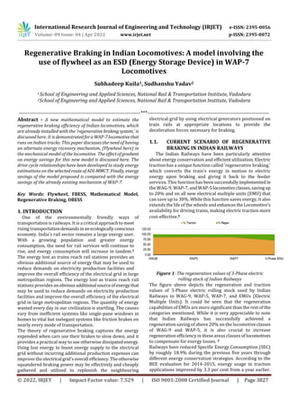
  • 1. International Research Journal of Engineering and Technology (IRJET) e-ISSN: 2395-0056 Volume: 09 Issue: 04 | Apr 2022 www.irjet.net p-ISSN: 2395-0072 © 2022, IRJET | Impact Factor value: 7.529 | ISO 9001:2008 Certified Journal | Page 3827 Regenerative Braking in Indian Locomotives: A model involving the use of flywheel as an ESD (Energy Storage Device) in WAP-7 Locomotives Subhadeep Kuila1, Sudhanshu Yadav2 1 School of Engineering and Applied Sciences, National Rail & Transportation Institute, Vadodara 2School of Engineering and Applied Sciences, National Rail & Transportation Institute, Vadodara ---------------------------------------------------------------------***--------------------------------------------------------------------- Abstract - A new mathematical model to estimate the regenerative braking efficiency of Indian locomotives, which are already installed with the 'regenerative brakingsystem,'is discussed here. It is demonstratedforaWAP-7locomotivethat runs on Indian tracks. This paper discusses the need of having an alternate energy recovery mechanism, (Flywheel here) in the mechanical model of the locomotive. The effectofgradient on energy savings for this new model is discussed here. The drive cycle relationships have been developed to study energy estimations on the selectedrouteofADI-MMCT. Finally, energy savings of the model proposed is compared with the energy savings of the already existing mechanism of WAP-7. Key Words: Flywheel, FBESS, Mathematical Model, Regenerative Braking, OBESS 1. INTRODUCTION One of the environmentally friendly ways of transportation is railways. It is a critical approach to meet rising transportationdemandsinanecologicallyconscious economy. India's rail sector remains a large energy user. With a growing population and greater energy consumption, the need for rail services will continue to rise, and energy consumption will increase in tandem.1 The energy lost as trains reach rail stations provides an obvious additional source of energy that may be used to reduce demands on electricity production facilities and improve the overall efficiency of the electrical grid in large metropolitan regions. The energy lost as trains reach rail stations provides anobvious additional sourceofenergythat may be used to reduce demands on electricity production facilities and improve the overall efficiency of the electrical grid in large metropolitan regions. The quantity of energy wasted every day in our civilization is startling. The causes vary from inefficient systems like single-pane windows in homes to vital but inelegant systems like friction brakes on nearly every mode of transportation. The theory of regenerative braking captures the energy expended when cars use their brakes to slow down, and it provides a practical way to use otherwise dissipatedenergy. Using lost energy to boost energy supply to the electrical grid without incurring additional production expenses can improve the electrical grid'soverall efficiency.Theotherwise squandered braking power may be effectively and cheaply gathered and utilized to replenish the neighbouring electrical grid by using electrical generators positioned on train rails at appropriate locations to provide the deceleration forces necessary for braking. 1.1. CURRENT SCENARIO OF REGENERATIVE BRAKING IN INDIAN RAILWAYS The Indian Railways have been particularly attentive about energy conservation and efficient utilization. Electric traction has a unique function called 'regenerative braking,' which converts the train's energy in motion to electric energy upon braking and giving it back to the feeder services. This function has beensuccessfullyimplemented in the WAG-9, WAP-7, and WAP-5locomotiveclasses,savingup to 20% and on all new electrical multiple units (EMU) that can save up to 30%. While this function saves energy, it also extends the life of the wheels andenhancestheLocomotive's availability for driving trains, making electric traction more cost-effective.3 Figure 1: The regeneration values of 3-Phase electric rolling stock of Indian Railways The figure above depicts the regeneration and traction values of 3-Phase electric rolling stock used by Indian Railways in WAG-9, WAP-5, WAP-7, and EMUs (Electric Multiple Units). It could be seen that the regeneration capabilities of EMUs are more significant than the rest of the categories mentioned. While it is very appreciable to note that Indian Railways has successfully achieved a regeneration saving of above 20% on the locomotiveclasses of WAG-9 and WAP-5, it is also crucial to increase regeneration efficiency in these areas classes of locomotives to compensate for energy losses. 3 Railways have reduced Specific Energy Consumption (SEC) by roughly 18.9% during the previous five years through different energy conservation strategies. According to the BEE evaluation for 2014-2015, energy usage in traction applications improved by 3.3 per cent from a year earlier.
  • 2. International Research Journal of Engineering and Technology (IRJET) e-ISSN: 2395-0056 Volume: 09 Issue: 04 | Apr 2022 www.irjet.net p-ISSN: 2395-0072 © 2022, IRJET | Impact Factor value: 7.529 | ISO 9001:2008 Certified Journal | Page 3828 Over several years, Indian Railways has also received 87 energy conservation awards. 1.2 COMPARATIVE ANALYSIS OF REGENERATIVE BRAKING ENERGY SAVINGS: CASE OF INDIAN RAILWAYS NCR & UNITED KINGDOM SWR We have tried to compare the case of Indian Railways' North-Central Region and United Kingdom's South-West Region running trains with Regenerative Braking capabilities to conclude with what measure Indian Railways should rely upon for achievingan excellentenergy- saving index. NCR has saved over 15 million power units by running these trains with three-phaseinductiontractionmotors with regeneration capabilities.4 Cutting down to numbers, we have 400 electric locomotives running across NCR, out of which 100 have regenerative capabilities, and the15million kWh saving of electricity is due to these 100 three-phase induction traction motors fitted locomotives only. More than 200 electric trains on the South-West Trains network have had equipment installedaspartofthescheme. These trains serve Guildford, Alton, Portsmouth, Reading, Southampton, and Weymouth in the London suburbs. They've all been upgraded to include the new energy-saving technologies. The technique saves 50 million kWh of electricity each year, enough to power around 11,500 UK households for a year.5 We could conclude, from the figures below that despite having double the number of trains equipped with Regeneration capabilities, the energy saving is almost 3.5 times that of the NCR region. The track on which these figures have been taken has approximately the same track length, which Trains running in SWR Class 458 Class 444 Figure 3: Proportion of 3-Phase ITM locomotives from NCR makes the comparison fair enough to decide what extra technologies UK's SWR uses that make it such energy efficient. We will be talking about that part in later sections of our paper. 1.3 MODERN ELECTRIC RAIL VEHICLE: OVERVIEW & POWER FLOW IN WAP-7 LOCOMOTIVE WAP-7 is the 7th generation of WAP class locomotives, where W stands for broad gauge (Wide), A stands for AC Electric locomotive, and P for Passenger locomotive. WAG-9 is the 9th generation of WAG class locomotives, where W stands for the same broad gauge (Wide), A stands for AC Electric locomotive, and G for Goods or freight locomotive. The major components of this WAP-7 locomotive are a) Pantograph, which collects the high tension current (25 kV) from the contact wire, b) Voltage Regulating Equipment, where the main transformer, consistsofanAutotransformer with 32 taps and a stepped-down transformer with two distinct secondary windings, steps down the high OHE voltage to a low voltage, c)Silicon Rectifiers, which converts the alternating current provided by secondary windings of the main transformer is into direct current utilizing two silicon rectifiers (RSI), one each supplying to set off three traction motors, d)Traction Induction Motor, which is the prime mover of the locomotive. Generally, a three-phase Induction motor is used as the primarytractionmotordue to its Electromagnetic properties.6 Figure 2: Main Components of a Modern Electric Rail Vehicle The power flow through the locomotive happens wherein, the "traction sub-station," a single-phase step-down transformer is linked to the three-phase utility system, which feeds energy to the overhead line (high-voltage) and the rail ("ground"). The pantograph captures the AC power and is then provided to the vehicle. The Locomotive is fitted with appropriate equipment to enable the loco pilot to manage the train's speed according to requirements by regulating the applied voltage to traction motors. The 25KV, single-phase AC power is gathered from the OHE by a roof- mounted pantograph and stepped down by a transformerin typical locomotives. Before being supplied to the traction motors, this supply is converted to DC using a full-wave silicon rectifier and related smoothing filter.Thevariationof the AC input voltage to the rectifier via an on-load tap changing arrangement on the primary winding of the locomotive transformer is used to manage torque and speed.7 Figure 3: Simplified view of power flow in a WAP-7 locomotive The Locomotive'sprimarytransformerstepsdownthe25 kV overhead AC supply. It feeds it to a front end (line) dual 4- quadrant line converter, which converts the AC to DC using Pulse Width Modulation (PWM) to achieve a unity power factor. This supply is connected to an input side converter through a DC connection, which serves as an energy reservoir. The VVVF Converter transforms the DC supply
  • 3. International Research Journal of Engineering and Technology (IRJET) e-ISSN: 2395-0056 Volume: 09 Issue: 04 | Apr 2022 www.irjet.net p-ISSN: 2395-0072 © 2022, IRJET | Impact Factor value: 7.529 | ISO 9001:2008 Certified Journal | Page 3829 into three phases, subsequently delivered to three-phase traction motors. The output of theDriveconverter(inverter) is a VVVF (Variable Voltage Variable Frequency) supply, which aids in adjusting the starting and operatingtorquesof three-phase traction motors to meet traffic needs. 1.4 BRAKING OF A WAP-7 LOCOMOTIVE In traction systems, there are two forms of braking:dynamic (electric) braking and classic friction braking. The produced current is used for regenerative braking when a traction motor is transferred toa generatorfordynamic braking. This braking is helpful for heavy-haul diesel electric locomotives operating on routes with significant downgrades. When regenerative braking is used to decelerate the train, the current in the electric motors is reversed.8 In a Conventional Friction Brake, the hydraulic mechanism mainly drives the braking system.Itconsistsofa primary, or master, cylinder filled with fluid and linked to a secondary or slave cylinder. When the brake pedal is depressed, a piston in the master cylinder depresses,forcing fluid through the circuit and into the slave cylinders at each wheel, which push the pistons to apply the brakes effectively. This system has improved over time with advancements like disc brakes, floating and multi-piston callipers, and power brakes, making braking more effective and comfortable for the driver, particularly with today's engines' more significant power outputs.9 Figure 4: Conventional Friction Braking of a WAP-7 locomotive Let us now look at the regenerative energy recovery mechanism used in Locomotive and the subsequent energy usage utilized by an accelerating train on the same contact line. It could be seen that the energy recovered by one train is sent back to the OHE line for other accelerating trains to feed upon it. Figure 5: Block diagram of energy recovery and usage on same OHE line by an accelerating train In Regenerative Braking of a WAP-7 locomotive, if we get energy back from the Traction motor, it acts as a generator, generating electrical energy from the kinetic energy when braked upon. So, in the case of regenerative braking, and Induction Motor acts as an Induction Generator. Induction Motor acts as an Induction generator when the slip becomes negative, i.e., when the slip of motor is less than 0, then kicks in the regenerative braking capability of the motor, and when the slip is greater than 0. The motor tractioncapability acts upon the device. S R S N N slip N   NS is synchronous speed and NR is speed of rotor In easy words: Slip>0, NS>NR: Induction Motor Slip<0, NS<NR: Induction Generator When the brakes are applied, the NS is reduced to such a level that the value of NS is less than the NR. Thus, the motor acts as a generator, generating electricity from the mechanical shaft movement due to inertia. NS could be altered as it depends upon the frequency of the Alternating Current supplied to the motor. The slip could be changed when braking is needed to make it less than 0. 10 By reducing the frequency of AC supply, we could suddenly reduce the NS or synchronous speed,butNRorthe rotor speed would not reduce suddenly due to the inertia it has gained by rotating. This is how the NS or the slip is changed for making the motor behaveasa generator. Weuse Variable Frequency Drives (VFD) to change the frequencyof the AC being provided to the motor. A variable frequency drive (VFD) is a motor controller that controlsthefrequency and voltage of an electric motor's power supply. As soon as the slip becomes negative, the motor's torque also becomes negative, i.e., it reverses the direction of applied torque. The torque of the motor tries to adjust itself by changing from negative to positive, but when the value of torque in its quest of becoming positive touches the value of 0, i.e., zero torque, the supply of current is cut down to the motor, which forces the motor to stop. We receive excess energy as an energy-saving from this regeneration mechanism. The same could be understood from the graph given below- Figure 6: Torque and Speed Characteristics of an Induction motor
  • 4. International Research Journal of Engineering and Technology (IRJET) e-ISSN: 2395-0056 Volume: 09 Issue: 04 | Apr 2022 www.irjet.net p-ISSN: 2395-0072 © 2022, IRJET | Impact Factor value: 7.529 | ISO 9001:2008 Certified Journal | Page 3830 2. MATHEMATICAL MODELING OFWAP-7TRAINS The mathematical model for WAP7 locomotive developed in this research uses the equations ofmotion.Thetractiveeffort Ftrac., track resistance force Tres, and the gradient force Tgrad are considered as the three main operating force on the train’s body. − − = · a= (1) Meff is the effective mass of the train, Fa is the net resultant force accelerating the train. 2.1. Equations governing train dynamics The motion of train is majorly governed by the newtons third law of motion. The effective mass of the train is dependent upon the mass of locomotives, tare mass of the carriages and the mass of the payload. (2) Here, Mloco is the mass of the locomotive, Ncarr Is the total number if the carriages, Mtare is the tare mass of the carriage and Mpayload is payload per vehicle. By using (1) and (2) we can find the acceleration as: (3) Tractive effort is the net force applied by the locomotive parallel to the direction of motion. The tractive effort is constrained by the motor current limits and the mechanical restriction. Values of the starting effort, continuous traction effort and braking effort is taken from the official documentation. A train's track resistance is its velocity- dependent resistance to motion. The semi-empirical Davis equation is commonly used to calculate resistance. = + + (4) DA ,DB ,DC are the coefficients for the various frictional force. Effect of gradient with θ as track gradient calculated as: (5) 2.2. Train Parameters The focus of our study is the WAP 7 locomotive, for that we have chosen Shatabdi Express through the route ADI-MMCT (Ahmedabad Jn – Mumbai Central) would be used. This convoy is chosen because it is one of the fastest convoys on one of the busiest sections. The data used is given in the table below. Table 1 – Data for WAP 7 and Shatabdi Convoy 2.3. Drive Cycle and Energy Estimation A driving cycle is necessary to evaluate the train's energy consumption because the efficiencyofahybridpowertrainis highly dependent on the duty cycle as well as route parameters. We used the data available on the Ahmedabad- Mumbai route of Shatabdi express for recreating the driving cycle in simulation. The recreated driving cycle's distances and time were tested and validated against figures given by erail.in. Table (2) below shows the input used for the driving cycle, which should be read from left to right. Sr no. Station waitin g time (sec) Trave l Time (sec) Distance (m) 1 Ahmedaba d 0 2040 45000 2 Nadiad 120 1020 19000 3 Anand 120 1800 35000 4 Vadodara 300 2820 71000 5 Bharuch 120 2760 58000 6 Surat 300 3840 93000 7 Vapi 120 5220 140000 8 Borivali 180 3420 30000 9 MMCT 0 Table 2 – Route data for drive cycle The track's gradient data is not given, but the model can handle gradients, allowing broad dependencies on uniform gradients to be demonstrated. Based on a modified version of the velocity-step approach (Ref. Jong J-C, Chang S), driving cycle is created. The driving cycle is set up to correspond to the distance and time requirements listed in data table provided above. The approach is modified by introducing a constant velocity part in the simulation that helps in meeting the timeframefor the given distance. There are three phases to each driving section: acceleration, constant velocity motion, and deceleration as depicted in the figure given below. The acceleration (section a), constant speed (section b) and deceleration trajectory (section c).
  • 5. International Research Journal of Engineering and Technology (IRJET) e-ISSN: 2395-0056 Volume: 09 Issue: 04 | Apr 2022 www.irjet.net p-ISSN: 2395-0072 © 2022, IRJET | Impact Factor value: 7.529 | ISO 9001:2008 Certified Journal | Page 3831 Figure 7: Drive cycle, showing the three sections Accelerationstartsat each stationand establishes a constant speed, while the deceleration trajectory (section c) is dependent upon, thenextarrivingstation,brakingpowerand safety and comfort restrictions. Distance covered in all the three phases are computed concurrently as the velocity is increased in each step in an iterative manner. As the net distance travelled (area under the velocity time curve) matches or exceeds the driving length of thegivensectionwe stop the acceleration. Then the train travels at a constant speed for a pre decided length, and then starts to deaccelerateas it reaches the calculated braking distance.As a result, the time criteria are met precisely, whereas the distances are near accurate. After using equation 3 for determining acceleration, we moved on to determining velocity, formula used for that is. (6) The distance covered was updated using following equation. (7) The data vital to this simulation is the power consumption throughout the journey. The instantaneous tractive power required by the train is determined by: (8) The energy consumption and energy recovered by the regenerative braking are what we're interested in. The following is the formula for energy. (9) The energy consumption during the traction will be calculated by using: (10) The energy recovered during the braking of train will be calculated using: (11) 2.4. Implementation In Python, numerical model incorporating all the equations discussed above was created.Drivingcycleiscomputedafter taking in the input of route profile, train parameters and other constraints. The velocity-step algorithm is applied at every section of track. Continuouscomputationisperformed to calculate the distance traveled and braking distance required. For each velocity step, it starts with calculatingthe force required to overcome the force of friction and other resistances. Then it moves onto calculate the resultant acceleration using the equation (3) provided above. Further it updates the velocity and acceleration using equations 6 and 7. Next it checks the braking distance and braking time required to stop this train, after this the time for which the train will run at a constant speed is calculated. The distance travelled in all three (accelerating, constant speed, braking) phases is added up. This process is repeated until the sum of distances meet the prescribed distance of the section. After generating the drive cycle all time-dependent kinematic variables and forces are calculated, and the energy consumption is evaluated during postprocessing using the equations 10 and 11. Below is the flow chart depicting the outline of the whole process implemented to obtain results. Figure 8: Basic modules and steps used in Python modelling 3. RESULTS Below are the results and graphs obtained from the simulation. This simulation estimates the total energy consumed by the train in traction, we can use this to compute the energy taken from substation using equation 12. (12) Here E_trac^Ac is the total energy takenfromthesubstation, E_trac^ is the traction energy obtained from equation 10. η_1 is the induction motor’s efficiency to convert the input electrical energy to output traction energy. Similarly, simulation also produces the cumulative braking energy produced during drive cycles. We can use this to obtain the net amount of energy arriving at the flywheel by using equation (13). (13)
  • 6. International Research Journal of Engineering and Technology (IRJET) e-ISSN: 2395-0056 Volume: 09 Issue: 04 | Apr 2022 www.irjet.net p-ISSN: 2395-0072 © 2022, IRJET | Impact Factor value: 7.529 | ISO 9001:2008 Certified Journal | Page 3832 Recovered energy is equal to the multiplication of energy stored in flywheel with flywheel’s efficiency. (14) In the equation (13) is the energy reaching the flywheel energy storage system (FESS). Multiplied with efficiency of the FESS we obtain that is the energy stored in the FESS. Since the energy must again pass through the induction motor to reach the wheelsofthetrain, the energy recovered is equal to the energy collected by the FESS multiplied by . (15) We also obtain the value of efficiency gain, which is defined as the ratio of energy recovered to the ratio of energy spent through-out the trip (16). As well as the value of energy recovery efficiency which is defined as the ratio of energy recovered to braking energy (17). (16) (17) 3.1. Results for zero gradient Graphs below of passenger stock (18 LHB II Ac Coaches) being pulled by the WAP 7 locomotive on the route shownin table 1. Velocity-Time Curve The maximum velocity attained 28.72 m/s. Acceleration-Time curve Peak acceleration for this run is 0.31m/s2, peak deacceleration is 0.051m/s2. Power-Time curve Peak accelerationpowerforthisrunis4.79Megawatts, peak power during deacceleration is -1.54 Megawatts. Traction Energy-Time curve Total consumption of energy in whole travel time is 4.65×10⁹ watt-hrs. Braking Energy-Time curve Total consumption of energy while braking is 2.304*109 watt-hrs. Table below shows the various combinations of passenger stock being pulled by the WAP 7 locomotive on the route shown in table 1. The value for the efficiency of induction motor is taken as 0.88, and the efficiency of Flywheel as 0.90.
  • 7. International Research Journal of Engineering and Technology (IRJET) e-ISSN: 2395-0056 Volume: 09 Issue: 04 | Apr 2022 www.irjet.net p-ISSN: 2395-0072 © 2022, IRJET | Impact Factor value: 7.529 | ISO 9001:2008 Certified Journal | Page 3833 Table 3: Estimated recovered energy for various train configurations on route shown in table 1 For a train consisting of 18 fully loaded LHB II AC coaches the total energy spent in traction is 5.29×10^6 kWh. The braking energy generated is 2.304×10^6 kWh. Total energy that can be recovered if on-board FESS is used 1.6×10^6 kWh, which is around 30% of total energy supplied for the traction. Similarly, for all other composition of the stock value of ε ranges from 0.29 to 0.31. Whereas the value of ϵ is constant for all the compositions. Figure 9: Comparison of trains running with and without FESS Total energy consumed over the trip represented by orange curve is 4.65×10^6 kWh and for the blue curveis2.36×10^6 kWh. Estimated energy savings by using FESS in this case is 2.29×10^6 kWh. 4. CONCLUSIONS The results show that utilizing the FESS can save a significant amount of energy. The estimated energy savings varied depending on the track, payload, number of cars per train, and kind of FESS. The net recovered energy ranges from 29-31% of the total energy consumed. With increasing gradient, the energy savings from a flywheel decreased due to less requirement of braking on up-terrain. The feasibility of a FESS for decreasing energy usage in passenger rail transportation systems is confirmed in this study. The technique and resultscanbeapplicabletovarious rail routes, even if the results were achieved for a specific route. 5. REFERENCES [1] Douglas, H.; Roberts, C.; Hillmansen, S.; Schmid, F. An assessment of available measures to reduce traction energy use in railway networks. Energy Conv. Manag. 2015, 106, 1149–1165, Available at: http://dx.doi.org/10.1016/j.enconman.2015.10.053 [2] Asegid Belay Kebede, Getachew Biru Worku, A research on regenerative braking energy recovery: A case of Addis Ababa light rail transit, Science Direct, 2021, Available at: https://www.sciencedirect.com/science/article/pii/S25901 16821000151 [3] Energy Scenario, RAILWAYS SYSTEM FOR ANALYSIS OF VIDYUT ENERGY, [online], no date, Available at: https://www.railsaver.gov.in/en_scenario.html [4] Ashraf Jamal, 'Regenerative braking helps Railways to save energy, money, Times of India, 26 September 2011 [online], Available at: https://timesofindia.indiatimes.com/city/allahabad/regene rative-braking-helps-railways-to-save-energy- money/articleshow/10131180.cm [5] South-West trains complete £2.2M investment in Regenerative Braking system to drive greener trains, News Releases, Stagecoach, 29 March 2012 [online] [6] M Tulbure, R Both, Models for AC locomotive Regenerative Braking, IEEE Xplore, [online], no date [7] How Electric Locomotives (Electric Trains) Work, StudyElectrical, 2019, [online] [8] Vlad Radu, Understanding Conventional Friction Brakes and the Regenerative Braking System, Autoevolution, 4 October 2020, https://www.autoevolution.com/news/understanding- conventional-friction-brakes-and-the-regenerative-braking- system-149614.htm [9] Regenerative Braking of Induction Motor, Electrical Yatra, [Blog], no date [10] Regenerative Braking of 3 Phase Induction Motor, Lecture 28, Electrical Yatra, 18 September 2018