TYPES OF ANTENNAS
AND
ITSAPPLICATIONS
Presented by
Dr.A.PramodKumar. M.Tech,Ph.D.
Assistant Professor
Department of ECE
Vardhaman College of Engineering
2.
Micro-strip Antennas
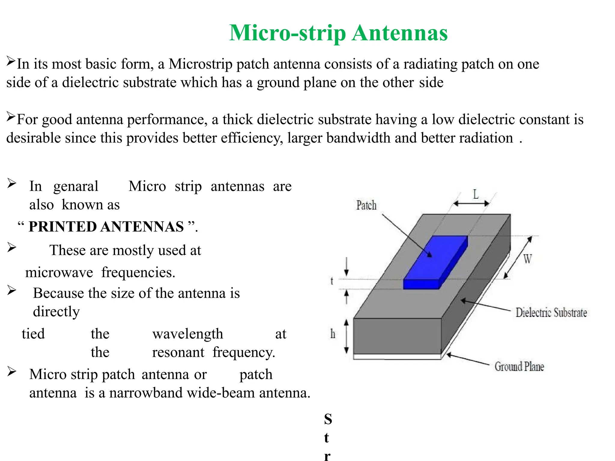
In itsmost basic form, a Microstrip patch antenna consists of a radiating patch on one
side of a dielectric substrate which has a ground plane on the other side
For good antenna performance, a thick dielectric substrate having a low dielectric constant is
desirable since this provides better efficiency, larger bandwidth and better radiation .
In genaral Micro strip antennas are
also known as
“ PRINTED ANTENNAS ”.
These are mostly used at
microwave frequencies.
Because the size of the antenna is
directly
tied the wavelength at
the resonant frequency.
Micro strip patch antenna or patch
antenna is a narrowband wide-beam antenna.
S
t
r
3.
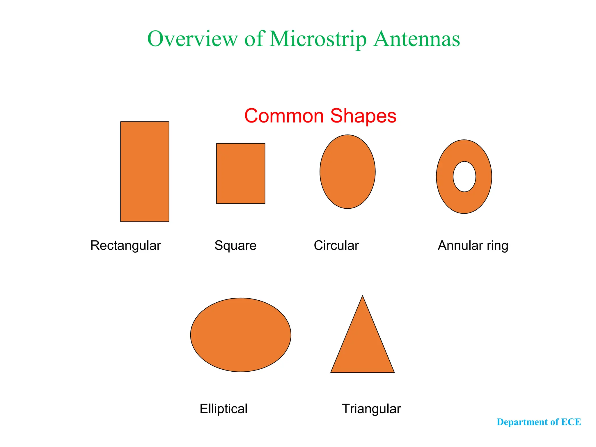
Overview of MicrostripAntennas
Common Shapes
Rectangular Square Circular
Elliptical
Annular ring
Triangular
Department of ECE
4.
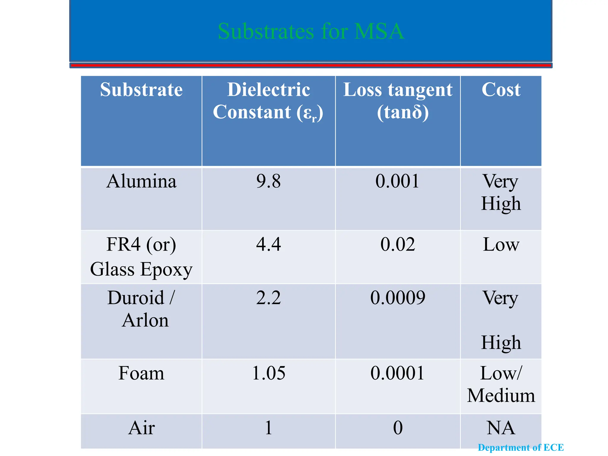
Substrates for MSA
SubstrateDielectric
Constant (εr)
Loss tangent
(tanδ)
Cost
Alumina 9.8 0.001 Very
High
FR4 (or)
Glass Epoxy
4.4 0.02 Low
Duroid /
Arlon
2.2 0.0009 Very
High
Foam 1.05 0.0001 Low/
Medium
Air 1 0 NA
Department of ECE
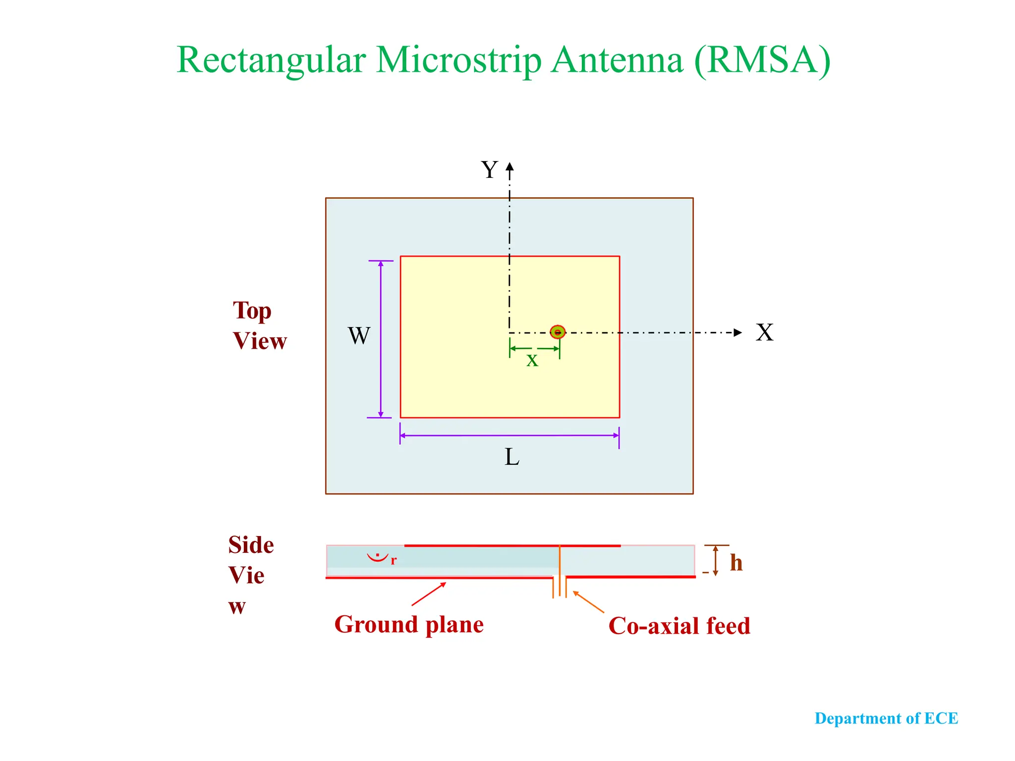
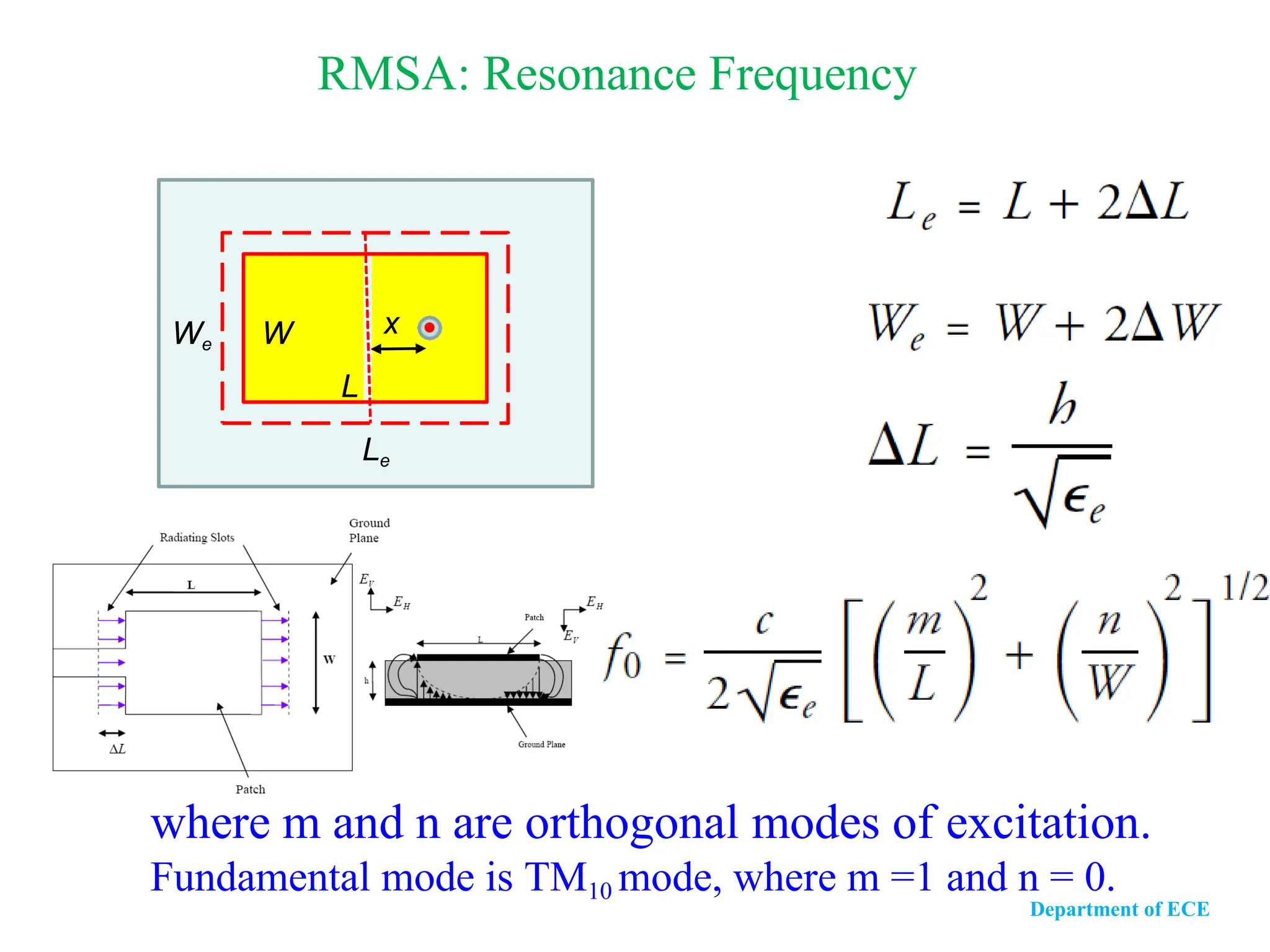
RMSA: Resonance Frequency
wherem and n are orthogonal modes of excitation.
Fundamental mode is TM10 mode, where m =1 and n = 0.
L
Le
We W x
Department of ECE
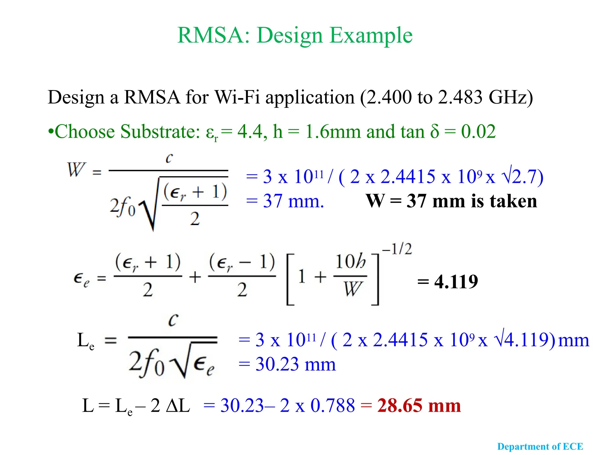
RMSA: Design Example
Designa RMSA for Wi-Fi application (2.400 to 2.483 GHz)
•Choose Substrate: εr = 4.4, h = 1.6mm and tan δ = 0.02
= 3 x 10¹¹ / ( 2 x 2.4415 x 109 x √2.7)
= 37 mm. W = 37 mm is taken
= 4.119
Le = 3 x 10¹¹ / ( 2 x 2.4415 x 109 x √4.119)mm
= 30.23 mm
L = Le – 2 ∆L = 30.23– 2 x 0.788 = 28.65 mm
Department of ECE
9.
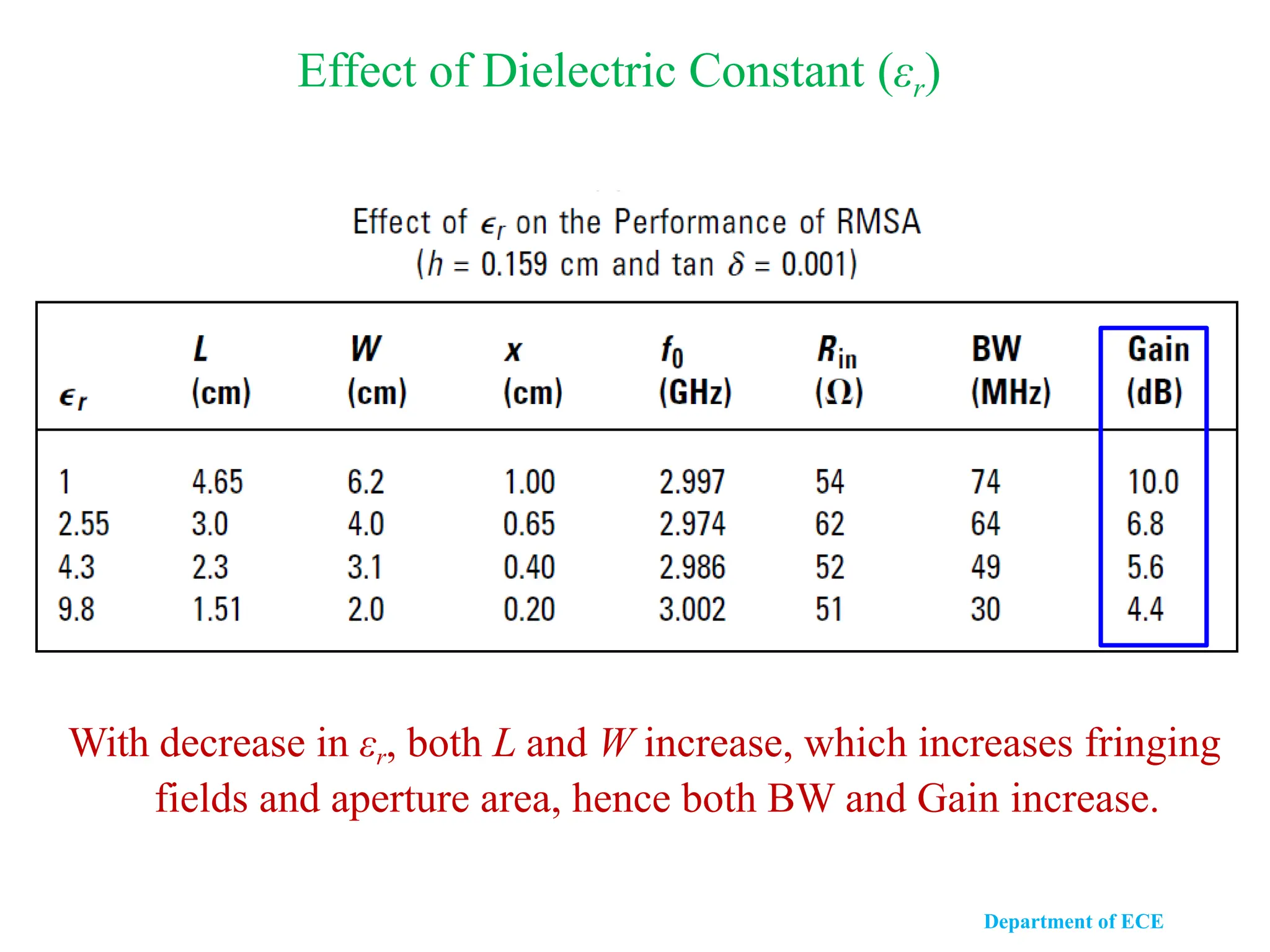
Effect of DielectricConstant (εr)
With decrease in εr, both L and W increase, which increases fringing
fields and aperture area, hence both BW and Gain increase.
Department of ECE
10.
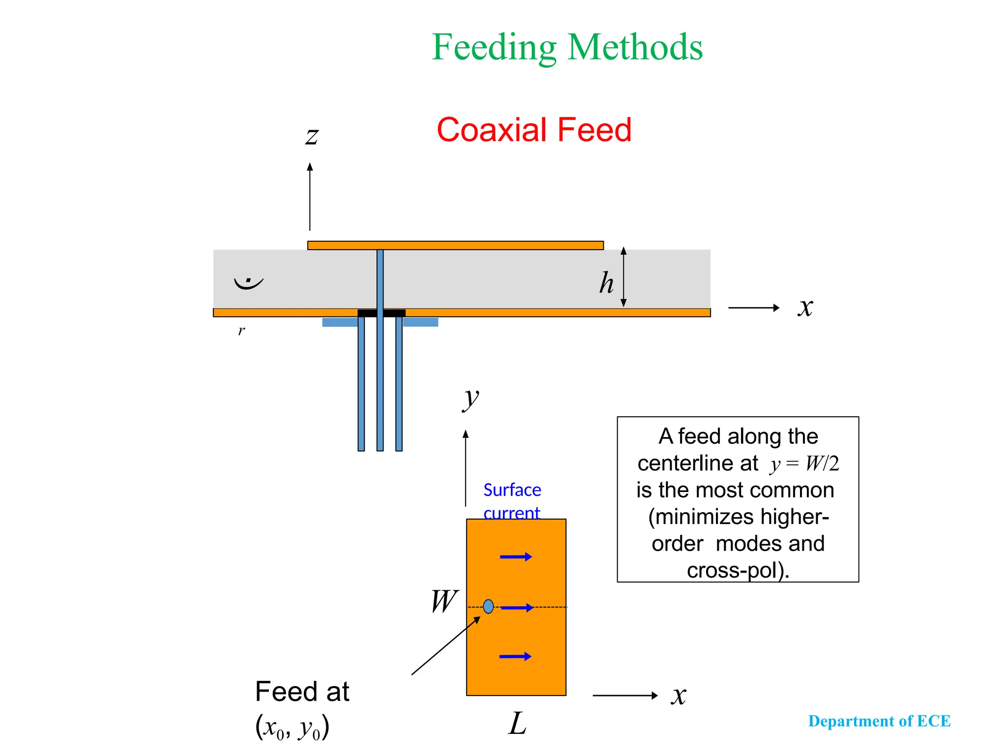
Coaxial Feed
A feedalong the
centerline at y = W/2
is the most common
(minimizes higher-
order modes and
cross-pol).
x
y
L
W
Feed at
(x0, y0)
Surface
current
x
r
h
z
Feeding Methods
Department of ECE
11.
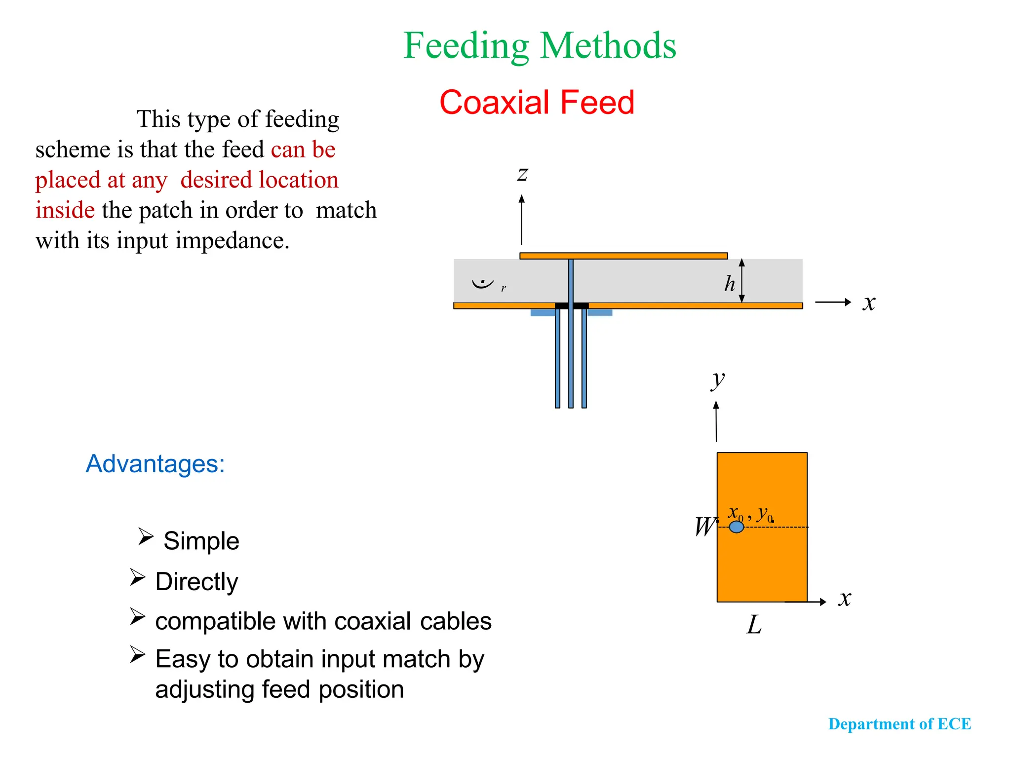
Advantages:
Simple
Directly
compatible with coaxial cables
Easy to obtain input match by
adjusting feed position
This type of feeding
scheme is that the feed can be
placed at any desired location
inside the patch in order to match
with its input impedance.
Coaxial Feed
x
r h
z
Feeding Methods
x
y
L
W
x0 , y0
Department of ECE
12.
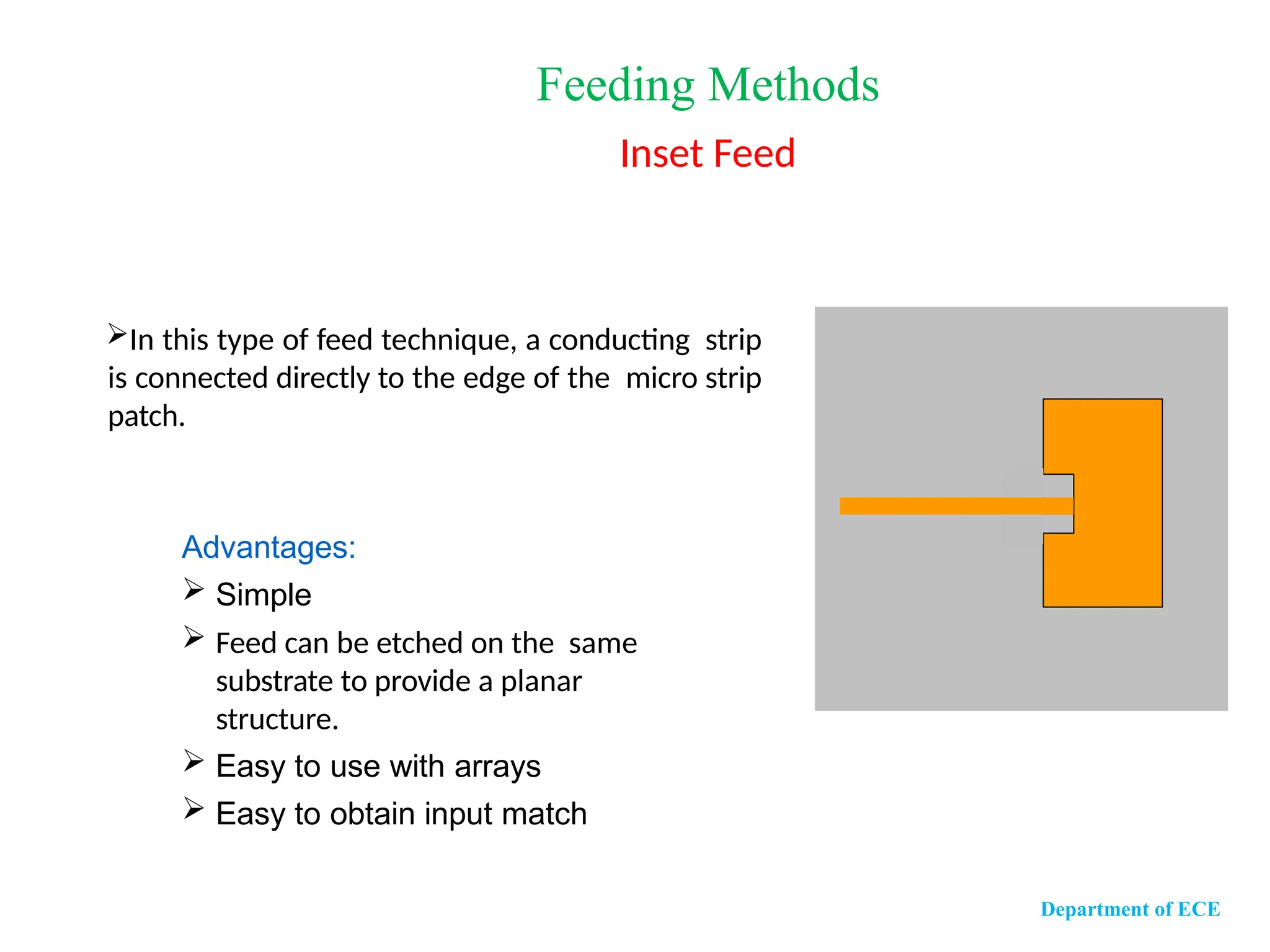
Advantages:
Simple
Feedcan be etched on the same
substrate to provide a planar
structure.
Easy to use with arrays
Easy to obtain input match
In this type of feed technique, a conducting strip
is connected directly to the edge of the micro strip
patch.
Feeding Methods
Inset Feed
Department of ECE
13.
Advantages:
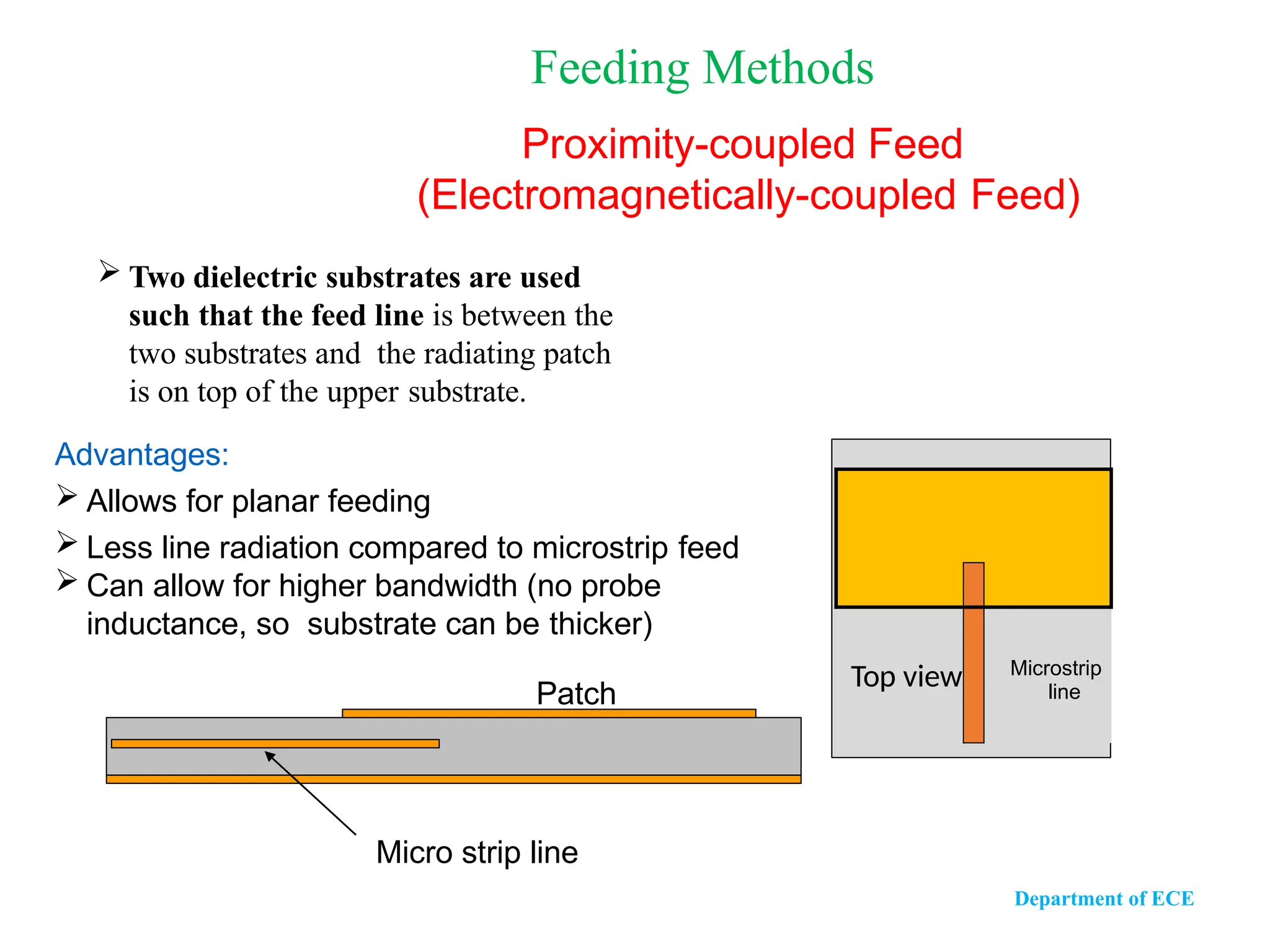
Allows forplanar feeding
Less line radiation compared to microstrip feed
Can allow for higher bandwidth (no probe
inductance, so substrate can be thicker)
Two dielectric substrates are used
such that the feed line is between the
two substrates and the radiating patch
is on top of the upper substrate.
Feeding Methods
Proximity-coupled Feed
(Electromagnetically-coupled Feed)
T
o
Top view Microstrip
line
Department of ECE
Patch
Micro strip line
14.
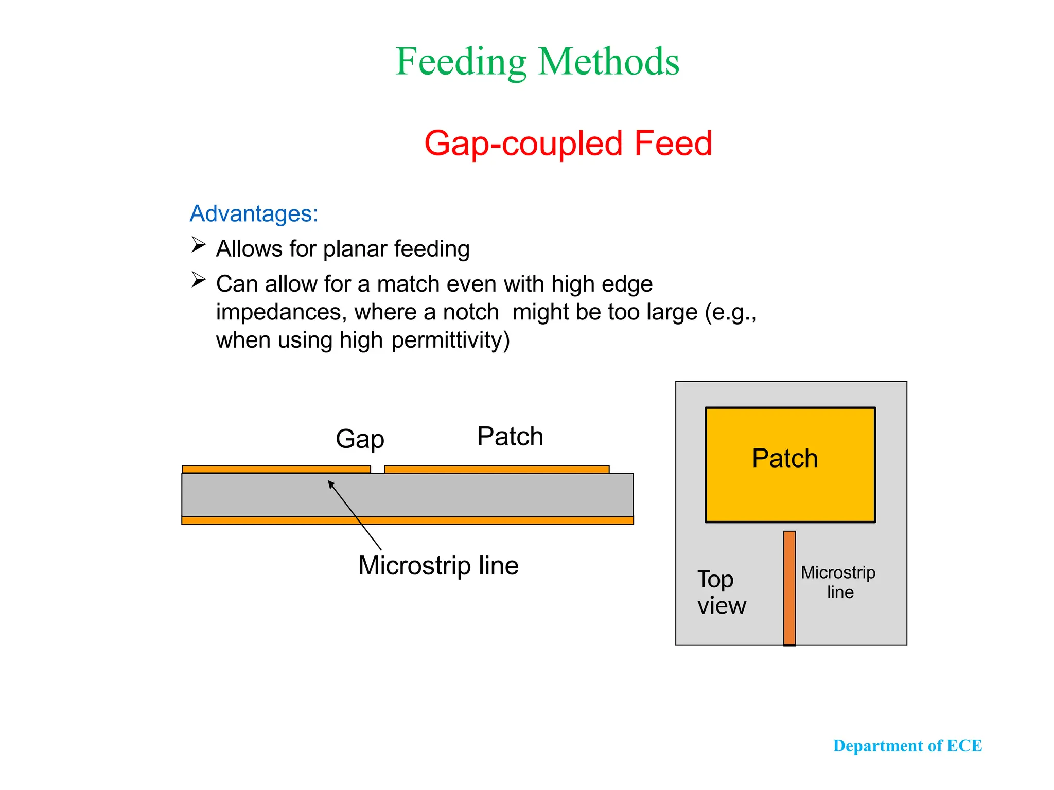
Advantages:
Allows forplanar feeding
Can allow for a match even with high edge
impedances, where a notch might be too large (e.g.,
when using high permittivity)
Microstrip line
Patch
Gap
Feeding Methods
Gap-coupled Feed
Patch
Top
view
Microstrip
line
Department of ECE
15.
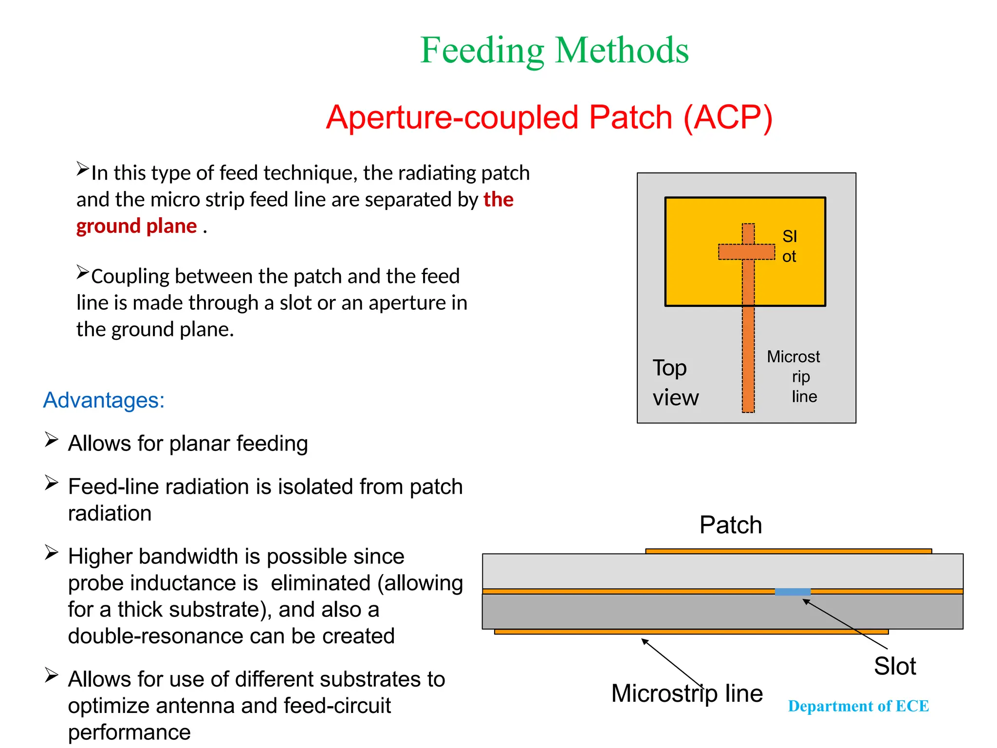
Advantages:
Allows forplanar feeding
Feed-line radiation is isolated from patch
radiation
Higher bandwidth is possible since
probe inductance is eliminated (allowing
for a thick substrate), and also a
double-resonance can be created
Allows for use of different substrates to
optimize antenna and feed-circuit
performance
In this type of feed technique, the radiating patch
and the micro strip feed line are separated by the
ground plane .
Coupling between the patch and the feed
line is made through a slot or an aperture in
the ground plane.
Patch
Microstrip line
Slot
Feeding Methods
Aperture-coupled Patch (ACP)
Top
view
Sl
ot
Microst
rip
line
Department of ECE
16.
Advantages
Light weight,low volume, low profile, planar
configuration, which can be made conformal
Low fabrication cost and ease of mass
production
Linear and circular polarizations are possible
Dual frequency antennas can be easily
realized
Feed lines and matching network can be easily
integrated with antenna structure
Department of ECE
17.
Applications
Pagers andmobile phones
Doppler and other radars
Satellite communication
Radio altimeter
Command guidance and telemetry in
missiles
Satellite navigation receiver
Biomedical radiator
Department of ECE
Introduction
In Reflector antenna,another antenna need to excite it.
Dipole
Horn
Slot
used for
excite so
called
primary
antenna
Reflector
called as
secondary
antenna DR. RAFAEL ABRANTES PENCHEL − IWT 2015
Department of ECE
20.
Reflector antennasare widely used to modify the radiation
pattern of a radiating element.
For example, the backward radiation from an antenna may be
eliminated with a plane sheet reflector of large dimensions.
In general, a beam of predetermined characteristics may be
produced by means of a large, suitably shaped and illuminated
reflector surface.
Reflector antennas are widely used for high gain antennas .
We can easily achieve above 30dB for microwave and higher
frequencies.
Department of ECE
21.
Types of Reflectors
Reflectorrepresent any shape most common
geometrics are
Flat sheet reflector or Plane reflector
Corner reflector
Curved or parabolic reflectors
Department of ECE
22.
Department of ECE
Flatsheet reflector or plane reflector
Simplest form of reflector antenna is kept infront of the feed
Energy is radiated in the desired direction
To increase the directivity, large flat sheet placed infront of the
half dipole
Main advantage is
Reduce backward radiation and increase gain in forward
direction
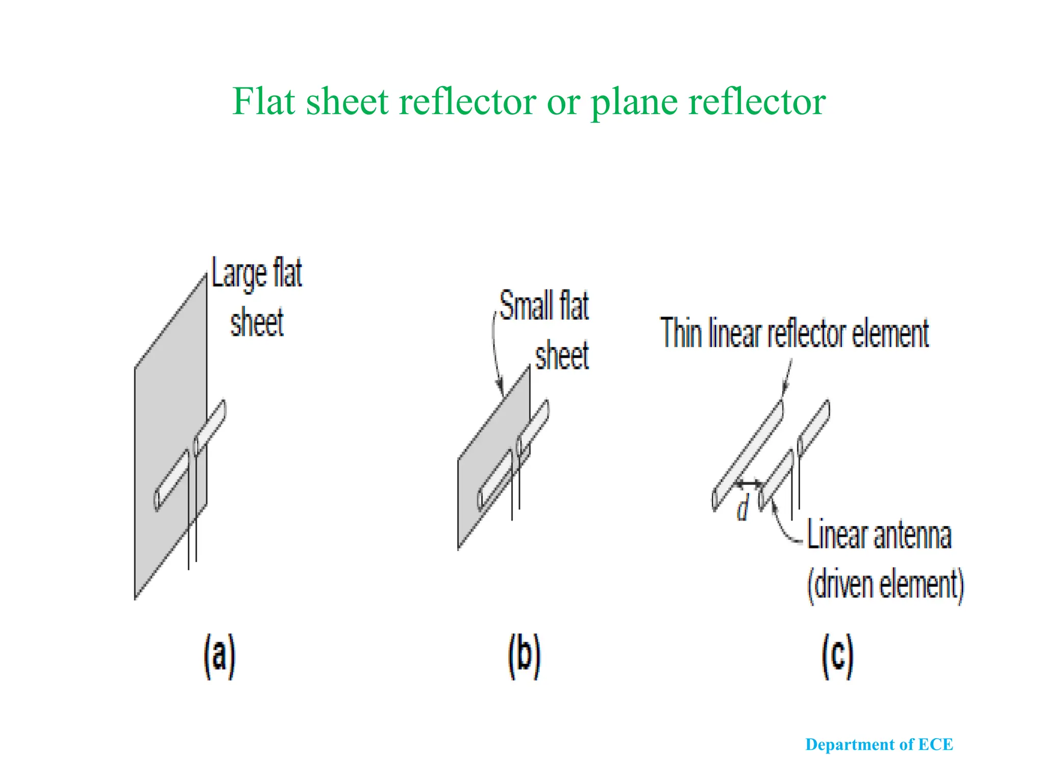
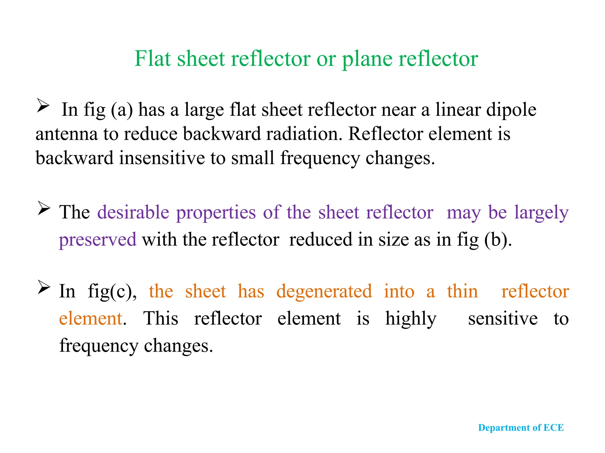
In fig(a) has a large flat sheet reflector near a linear dipole
antenna to reduce backward radiation. Reflector element is
backward insensitive to small frequency changes.
The desirable properties of the sheet reflector may be largely
preserved with the reflector reduced in size as in fig (b).
In fig(c), the sheet has degenerated into a thin reflector
element. This reflector element is highly sensitive to
frequency changes.
Flat sheet reflector or plane reflector
Department of ECE
Department of ECE
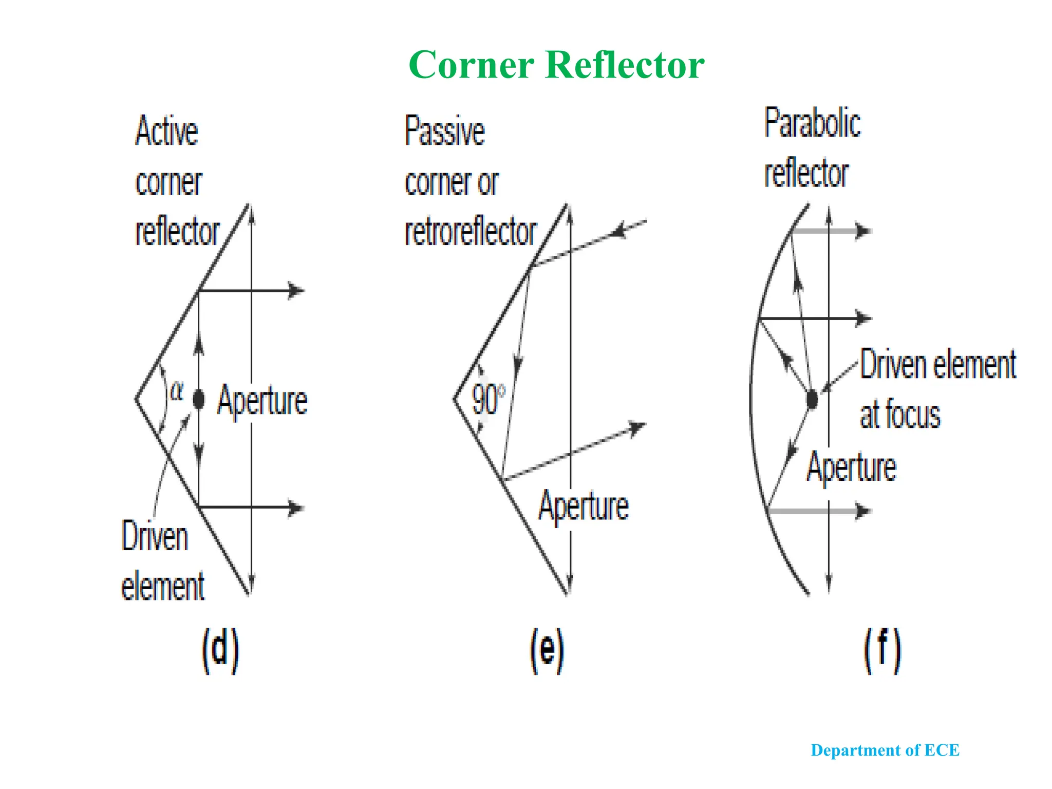
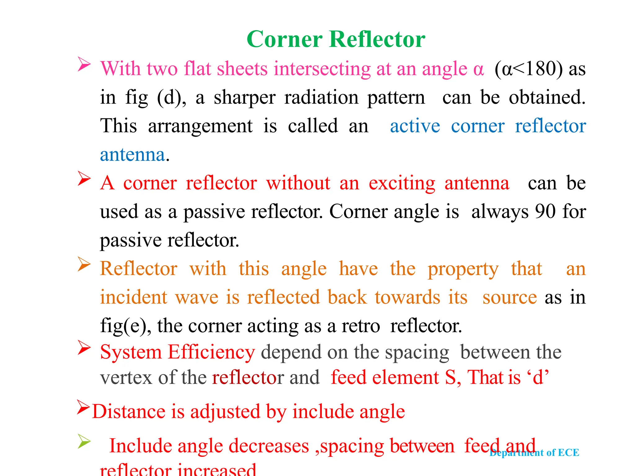
With two flat sheets intersecting at an angle α (α<180) as
in fig (d), a sharper radiation pattern can be obtained.
This arrangement is called an active corner reflector
antenna.
A corner reflector without an exciting antenna can be
used as a passive reflector. Corner angle is always 90 for
passive reflector.
Reflector with this angle have the property that an
incident wave is reflected back towards its source as in
fig(e), the corner acting as a retro reflector.
System Efficiency depend on the spacing between the
vertex of the reflector and feed element S, That is ‘d’
Distance is adjusted by include angle
Include angle decreases ,spacing between feed and
Corner Reflector
27.
Department of ECE
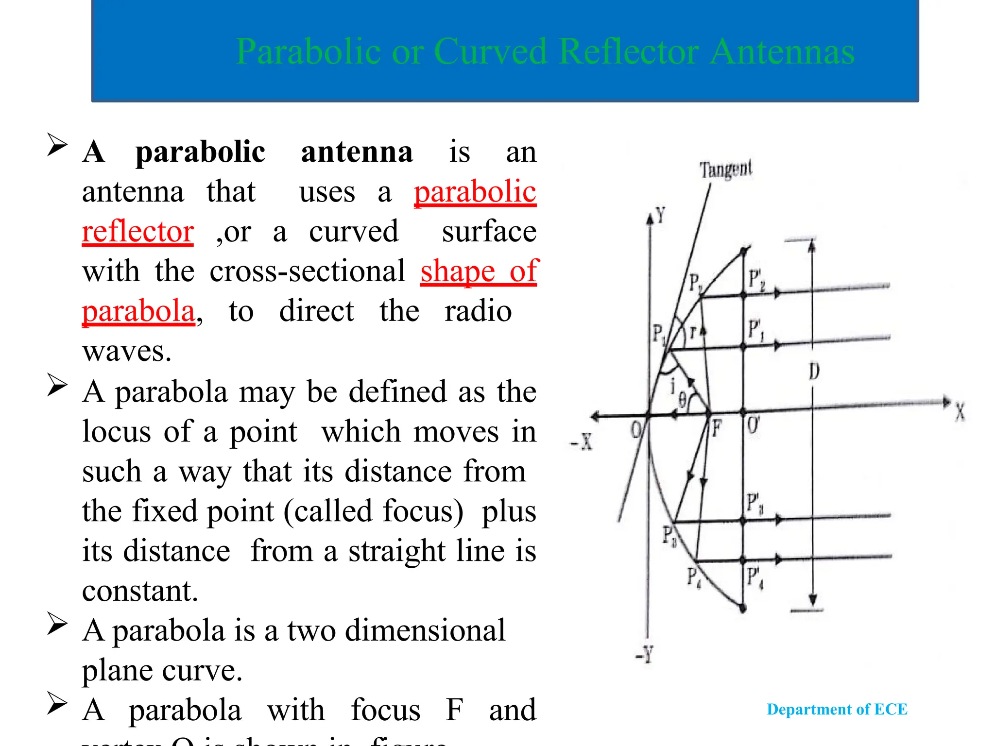
Parabolicor Curved Reflector Antennas
A parabolic antenna is an
antenna that uses a parabolic
reflector ,or a curved surface
with the cross-sectional shape of
parabola, to direct the radio
waves.
A parabola may be defined as the
locus of a point which moves in
such a way that its distance from
the fixed point (called focus) plus
its distance from a straight line is
constant.
A parabola is a two dimensional
plane curve.
A parabola with focus F and
28.
Department of ECE
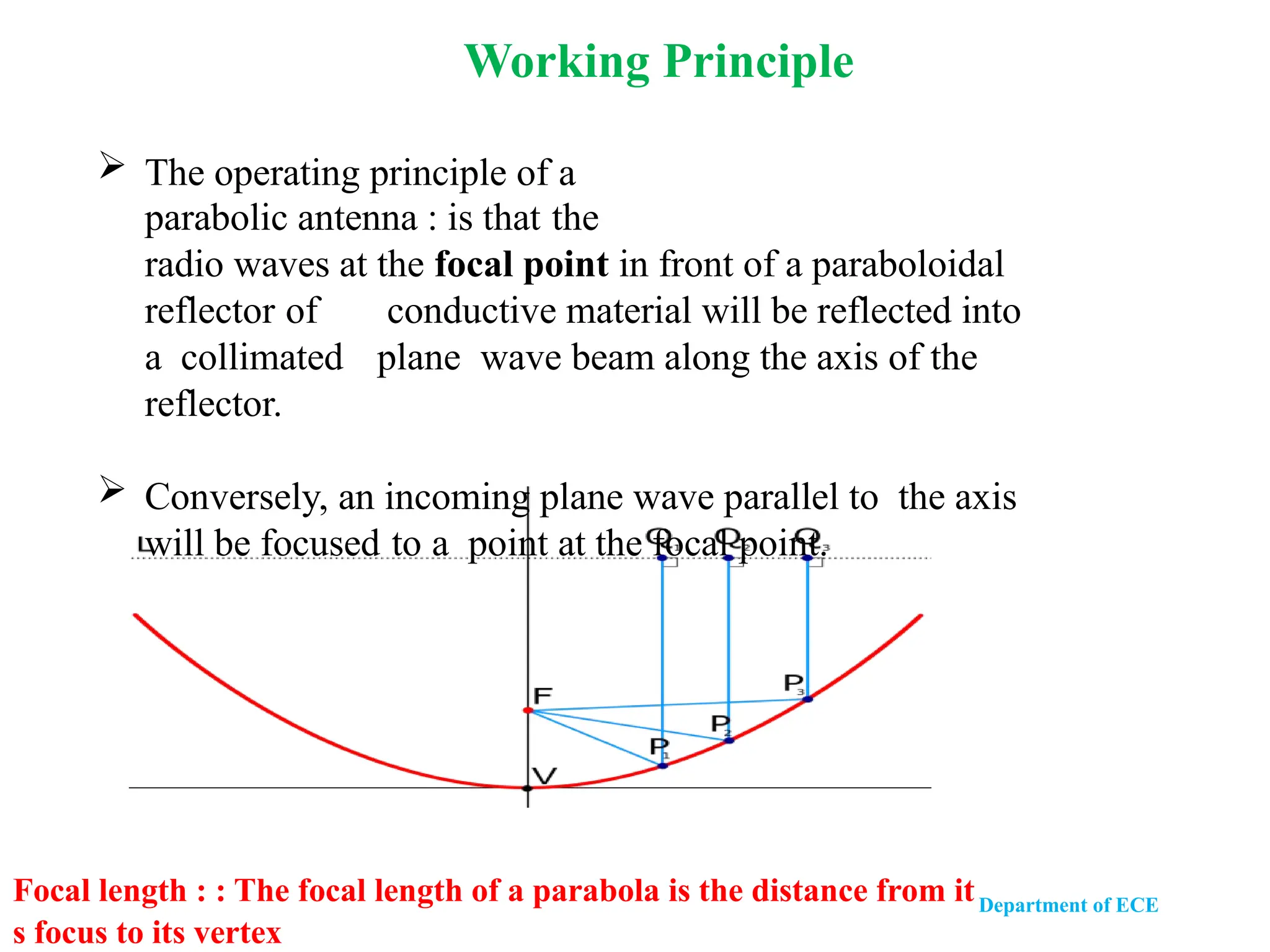
The operating principle of a
parabolic antenna : is that the
radio waves at the focal point in front of a paraboloidal
reflector of conductive material will be reflected into
a collimated plane wave beam along the axis of the
reflector.
Conversely, an incoming plane wave parallel to the axis
will be focused to a point at the focal point.
Focal length : : The focal length of a parabola is the distance from it
s focus to its vertex : The focal length of a parabola is the distance from its focus to i
Working Principle
29.
Department of ECE
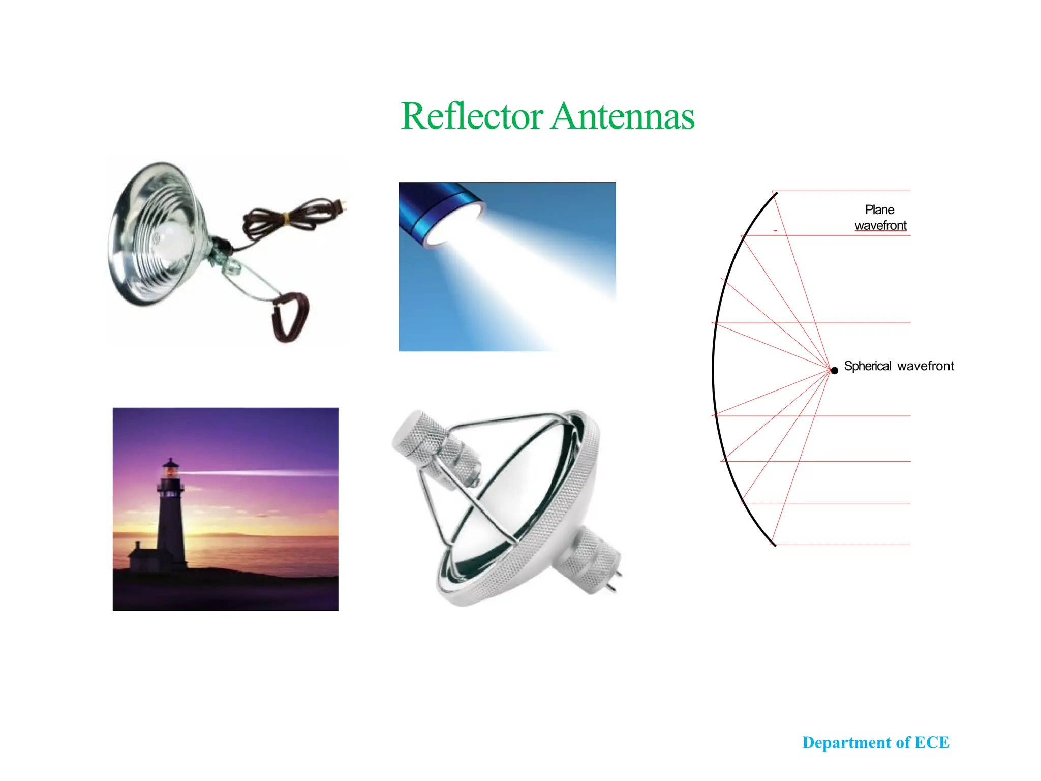
In fact, parabola converts a spherical wave front
coming from the focus into a plane wave front at the
mouth of the parabola as in fig .
This results that the reflected ray is parallel to the
parabolic axis, regardless of the particular value of Ө.
i.e., All the waves originating from focus will be
reflected parallel to the parabolic axis.
This implies that all the wave reaching at the
aperture plane are in phase.
According to law of reflection, the angle of
incidence and angle of reflection will be equal.
Cont- Working Principle
30.
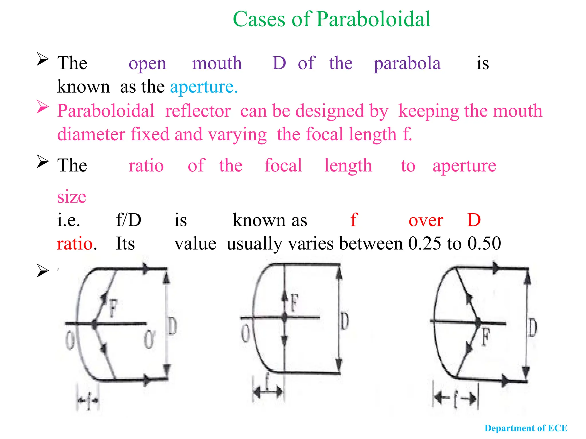
The openmouth D of the parabola is
known as the aperture.
Paraboloidal reflector can be designed by keeping the mouth
diameter fixed and varying the focal length f.
The ratio of the focal length to aperture
size
i.e. f/D is known as f over D
ratio. Its value usually varies between 0.25 to 0.50
There are 3 possible cases. (i) f<D/4 (ii) f= D/4 (iii) f>D/4
Cases of Paraboloidal
Department of ECE
31.
In thefirst case, the focal length is small such that the focus
lies well inside the mouth aperture. In this case it is difficult to
get a source giving adequately uniform illumination over
such a wide angle.
In the second case, the focus lies in the plane of the open
mouth. The focal length is equal to one fourth of open mouth
diameter. (D/4)
In the third case, when the focal length is large such that the
focus lies beyond the open mouth, it becomes difficult to focus
all the radiation from the source on the reflector.
Department of ECE
32.
Features of parabolicantenna
Greater directivity and Gain .
Parabolic or dish antennas are NOT frequency
dependant.
Receives and radiates signal in one direction only .
Produce sharp and narrow beam width of any antenna types .
Reduction in spill over and minor lobe radiation
Simple in construction
Quite inexpensive
Ability to place feed in a convenient location.
Department of ECE
33.
Department of ECE
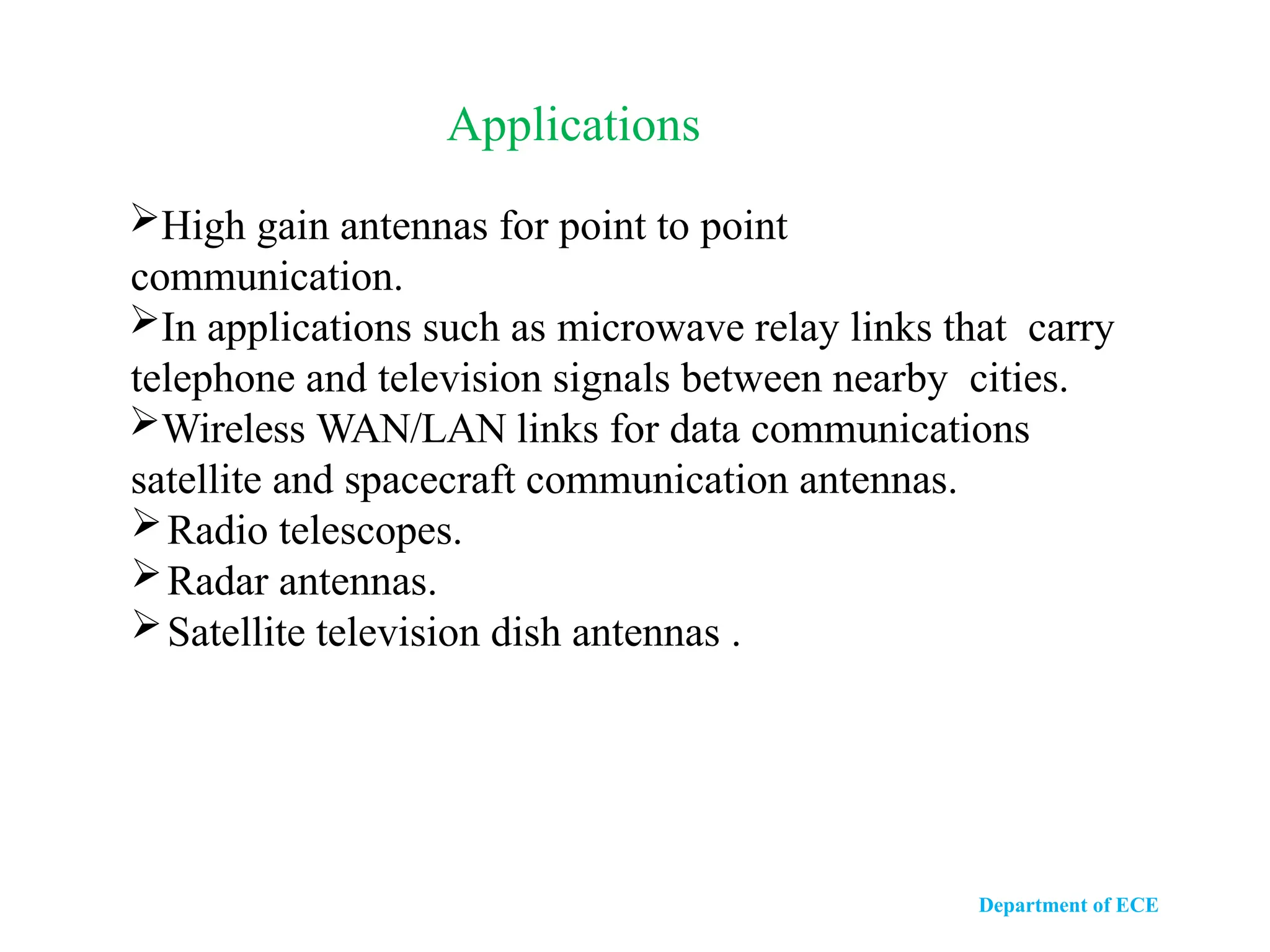
Highgain antennas for point to point
communication.
In applications such as microwave relay links that carry
telephone and television signals between nearby cities.
Wireless WAN/LAN links for data communications
satellite and spacecraft communication antennas.
Radio telescopes.
Radar antennas.
Satellite television dish antennas .
Applications
Department of ECE
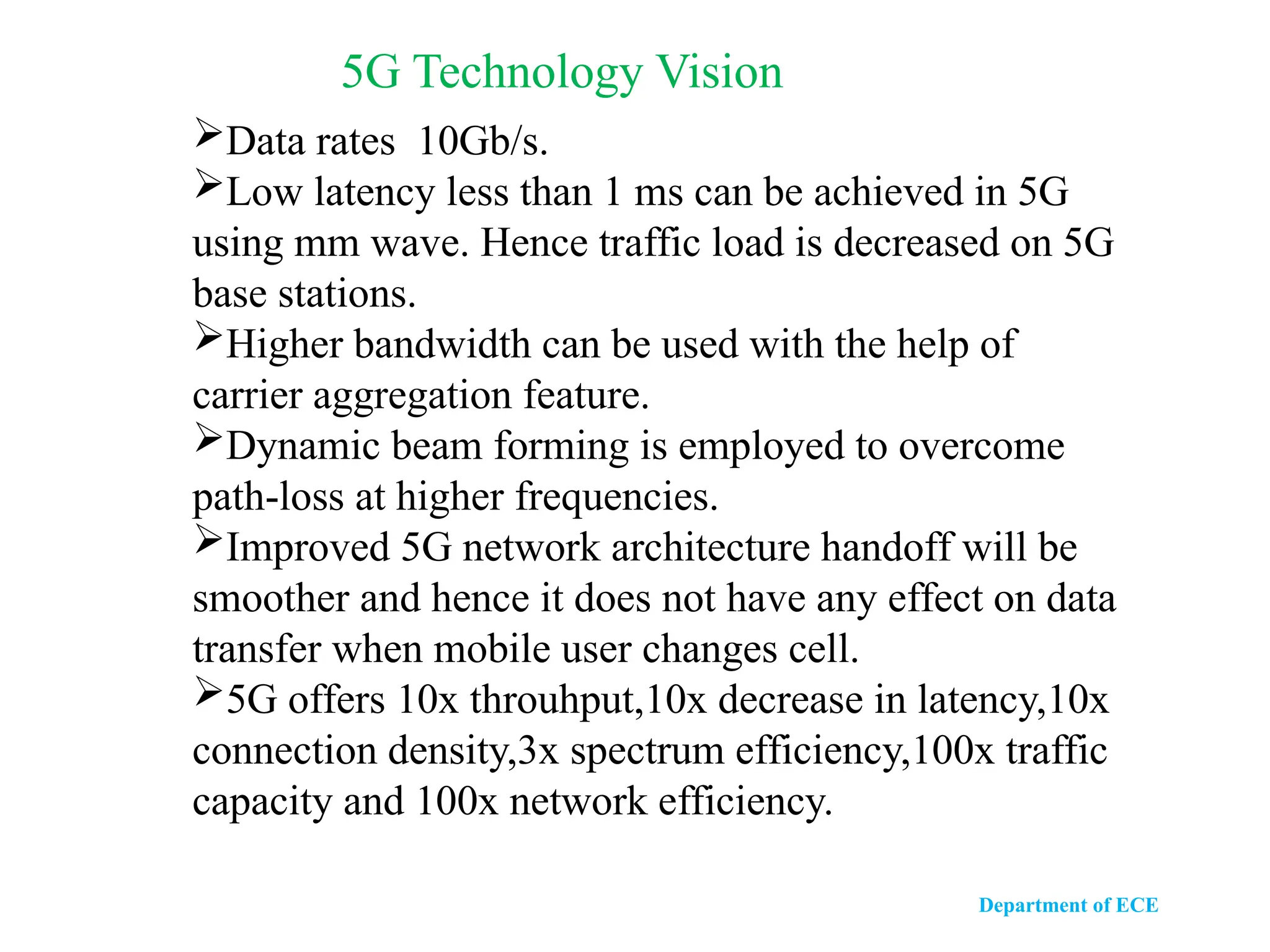
5GTechnology Vision
Data rates 10Gb/s.
Low latency less than 1 ms can be achieved in 5G
using mm wave. Hence traffic load is decreased on 5G
base stations.
Higher bandwidth can be used with the help of
carrier aggregation feature.
Dynamic beam forming is employed to overcome
path-loss at higher frequencies.
Improved 5G network architecture handoff will be
smoother and hence it does not have any effect on data
transfer when mobile user changes cell.
5G offers 10x throuhput,10x decrease in latency,10x
connection density,3x spectrum efficiency,100x traffic
capacity and 100x network efficiency.
36.
Department of ECE
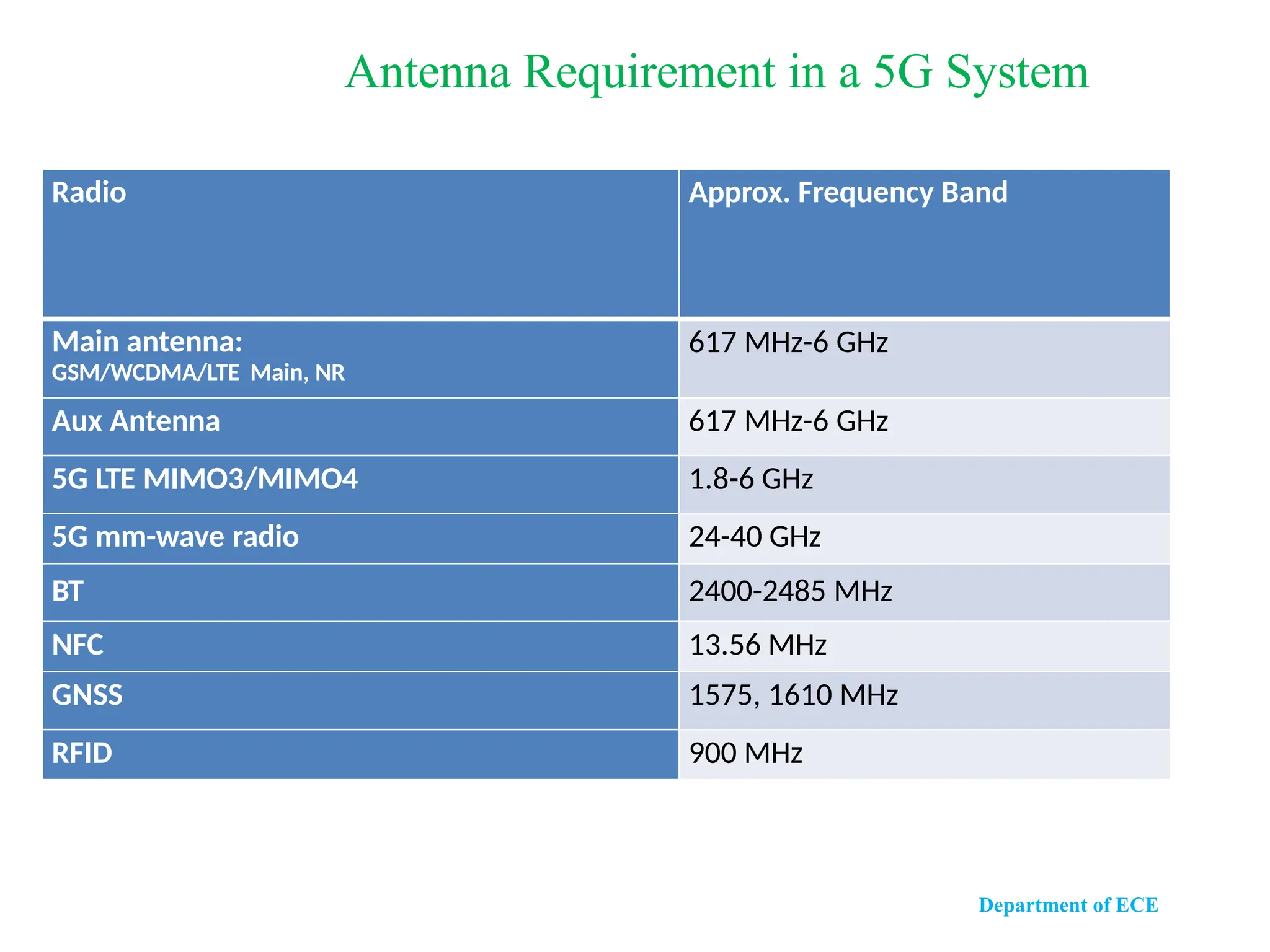
RadioApprox. Frequency Band
Main antenna:
GSM/WCDMA/LTE Main, NR
617 MHz-6 GHz
Aux Antenna 617 MHz-6 GHz
5G LTE MIMO3/MIMO4 1.8-6 GHz
5G mm-wave radio 24-40 GHz
BT 2400-2485 MHz
NFC 13.56 MHz
GNSS 1575, 1610 MHz
RFID 900 MHz
Antenna Requirement in a 5G System
37.
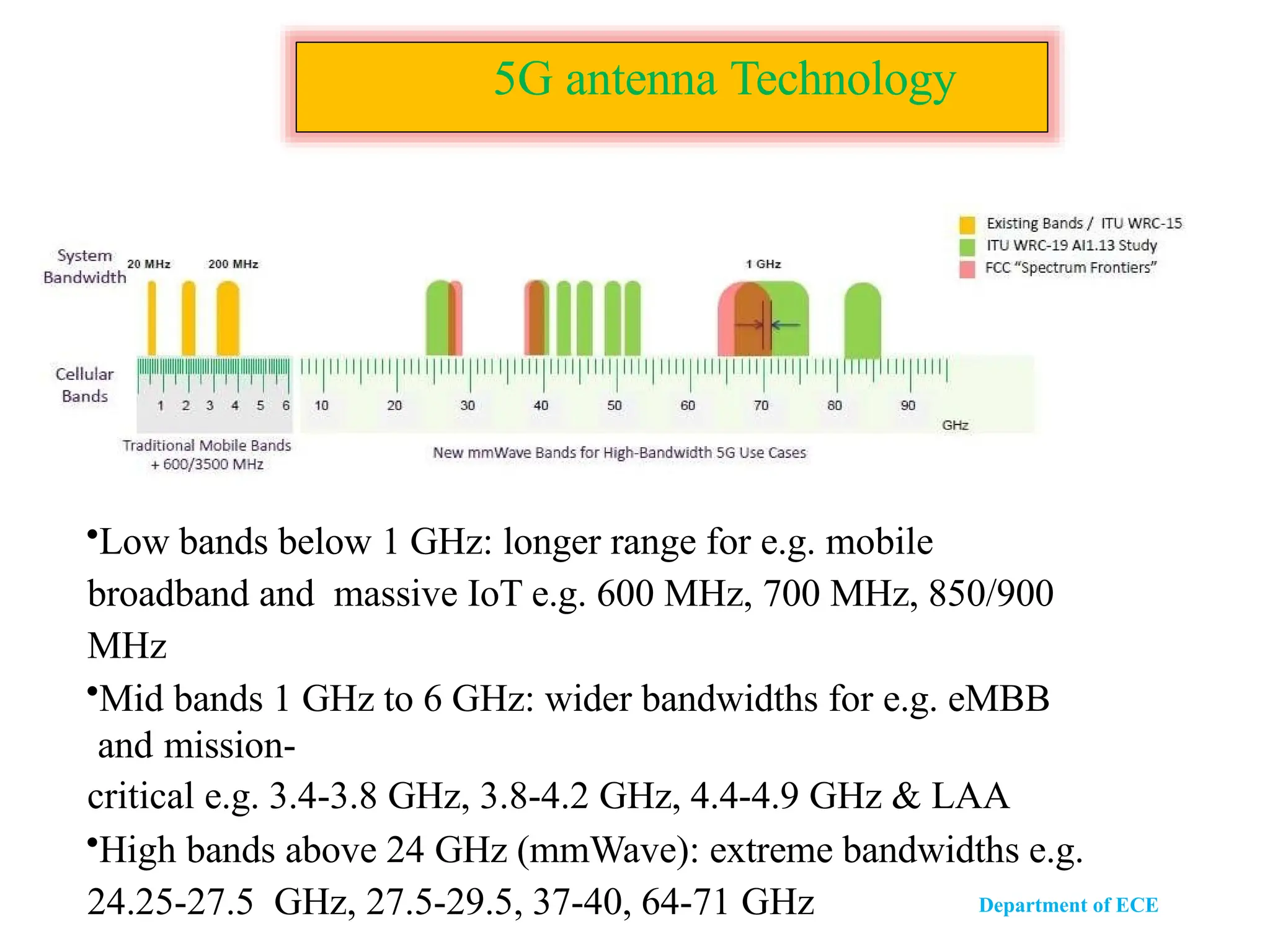
5G antenna Technology
•Lowbands below 1 GHz: longer range for e.g. mobile
broadband and massive IoT e.g. 600 MHz, 700 MHz, 850/900
MHz
•Mid bands 1 GHz to 6 GHz: wider bandwidths for e.g. eMBB
and mission-
critical e.g. 3.4-3.8 GHz, 3.8-4.2 GHz, 4.4-4.9 GHz & LAA
•High bands above 24 GHz (mmWave): extreme bandwidths e.g.
24.25-27.5 GHz, 27.5-29.5, 37-40, 64-71 GHz Department of ECE
38.
Department of ECE
Rx
Tx
X1
X2
-
Xn
Y1
Y2
-
Ym
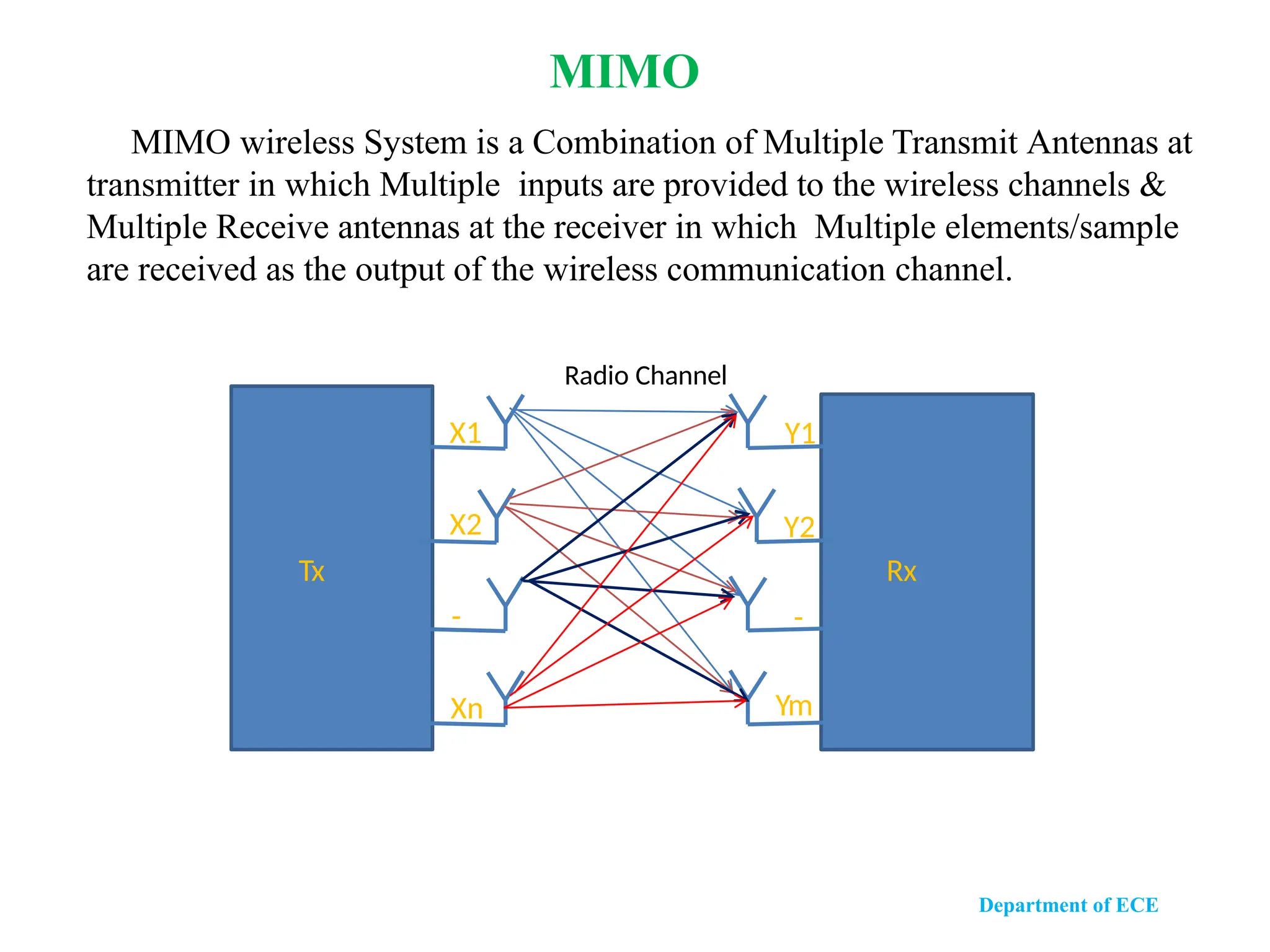
MIMOwireless System is a Combination of Multiple Transmit Antennas at
transmitter in which Multiple inputs are provided to the wireless channels &
Multiple Receive antennas at the receiver in which Multiple elements/sample
are received as the output of the wireless communication channel.
Radio Channel
MIMO
39.
1.Driverless automobiles
2.Wireline convergence
3.Massive Machine Type Communications (mMTC)
4.Ultra Reliable and Low Latency Communications (URLLC)
5.Satellite access.
6.Vehicle-to-Everything (V2X) communications
Department of ECE
Applications of 5G


![[BROCHURE] Italy Tour Project | @SlideON](https://cdn.slidesharecdn.com/ss_thumbnails/brochure8-251215152319-2805af68-thumbnail.jpg?width=640&height=640&fit=bounds)


