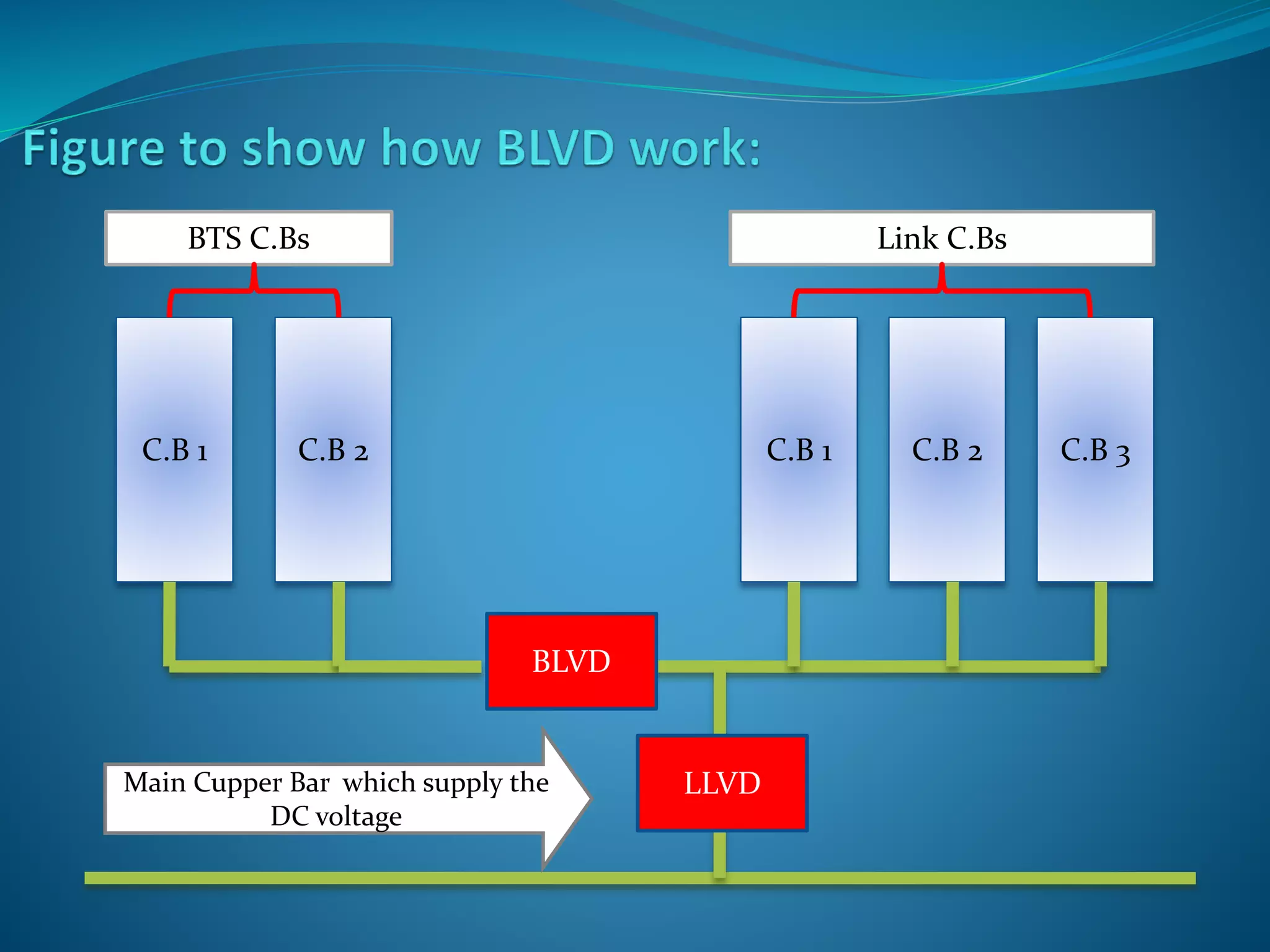
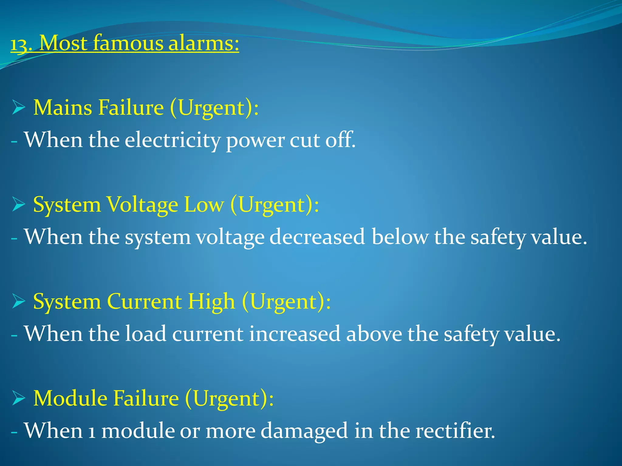
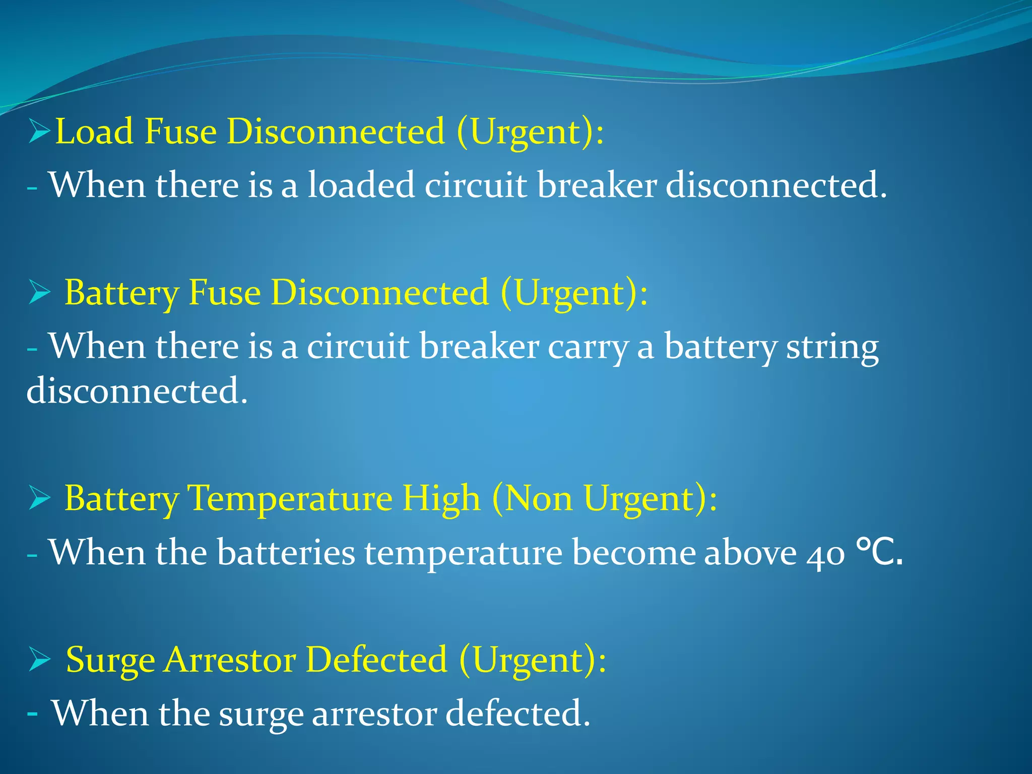
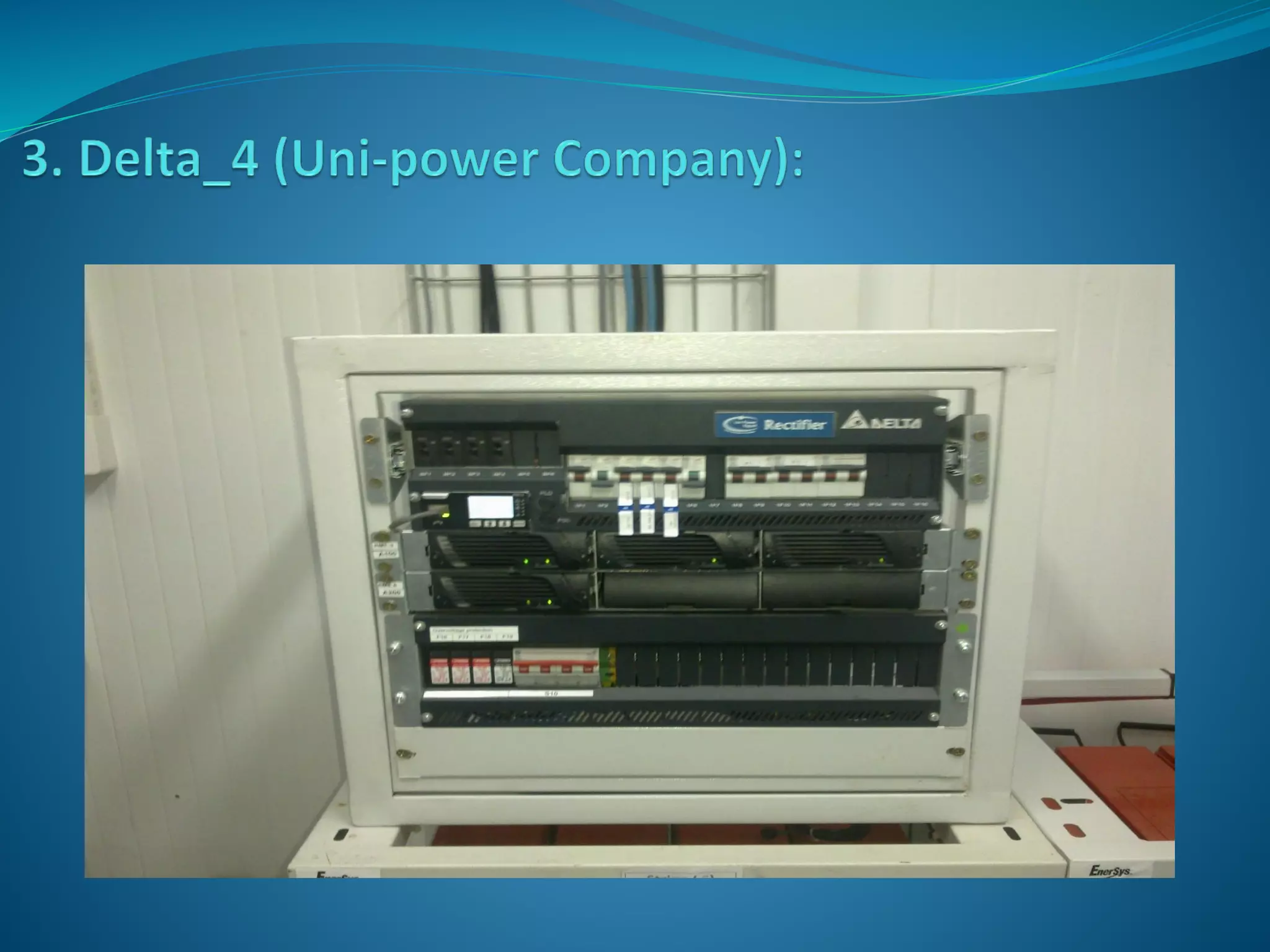
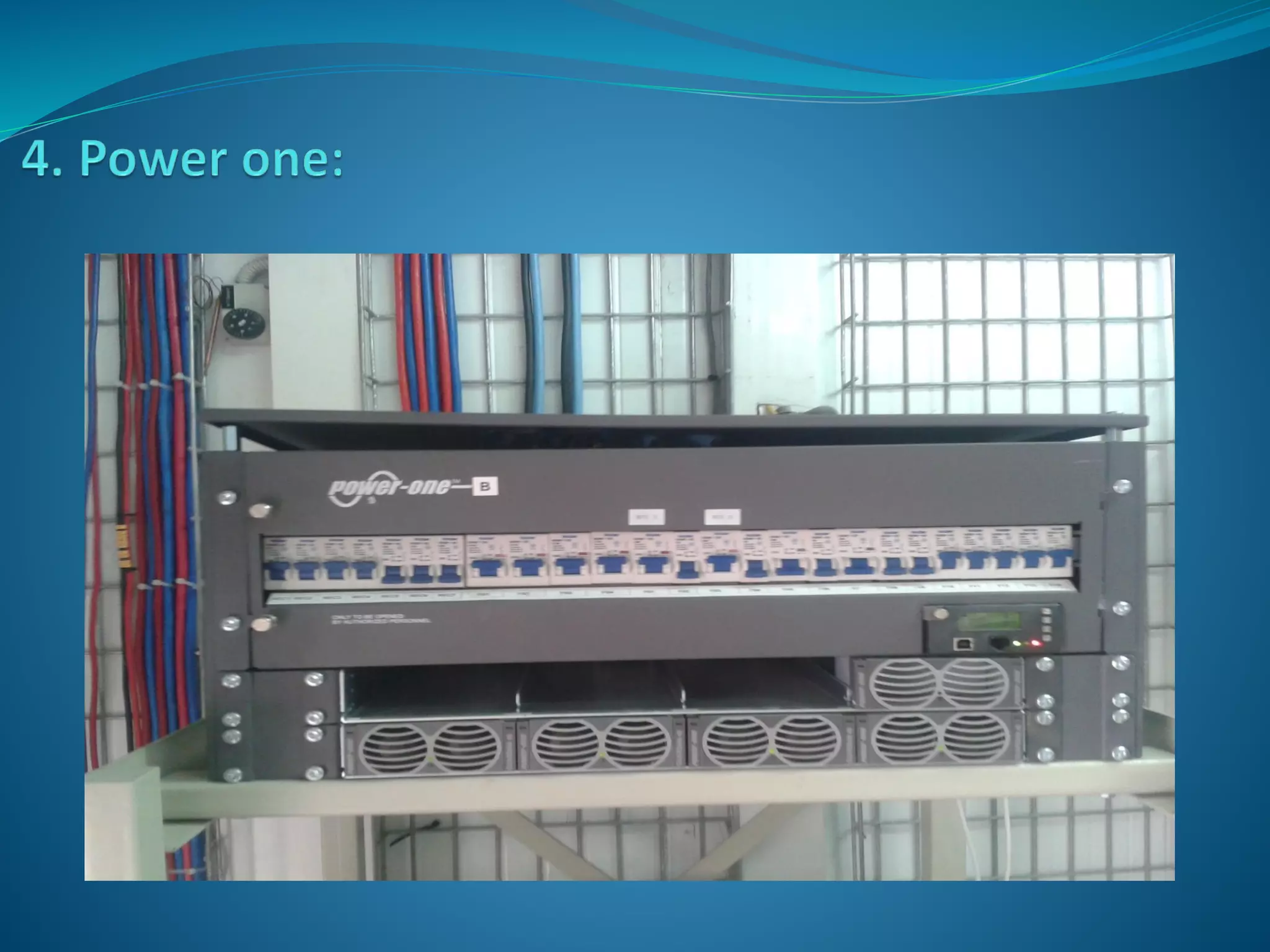
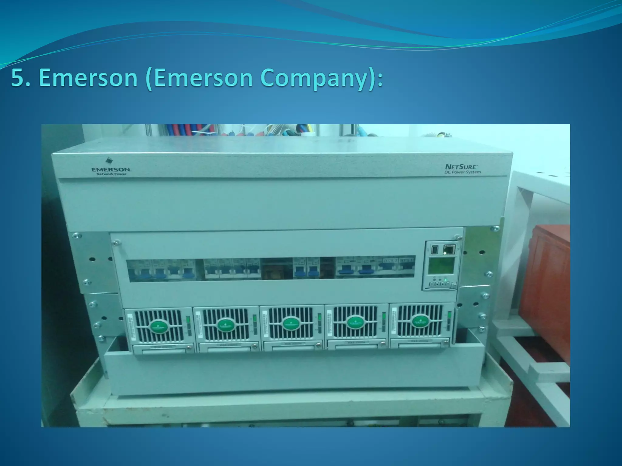
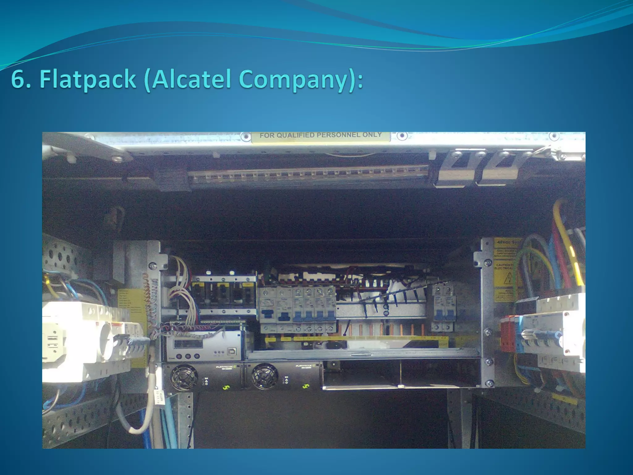
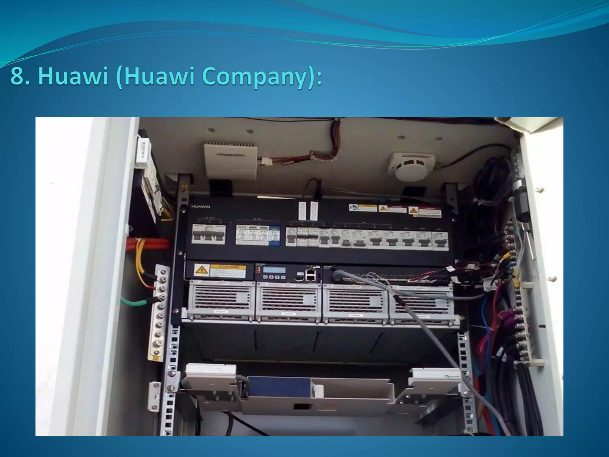
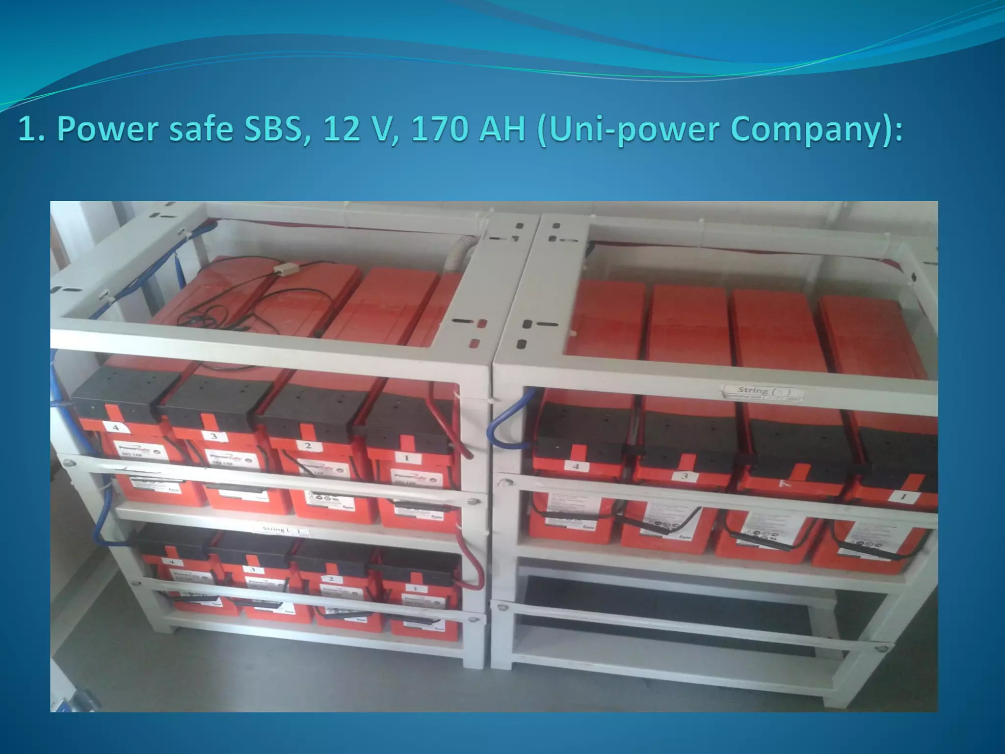
 Each site must have a rectifier as it is the way to convert the AC
voltage to DC voltage, and all our telecom equipments working
with DC voltage.
 In case of Solar Cell, the rectifiers not used as the Solar Cells
generate DC Voltage directly.
 Also the rectifiers responsible for charging the back up battery
system, which cover the site in the case of electricity cut off.
 There is a lot of types of the rectifiers, but all have the same
working concept as we will show.
Load C.Bs with
different ratings
to connect -ve
cables
3 Phase AC C.B
Rectifier Modules –
PSUs (Power
Supply Unit)
Rectifier
Display
Batteries C.Bs
Surge Arrestor
PSUs - Modules
C.Bs
Cupper bar to
connect +ve
cables
Cupper bar
connected to
C.Bs
1. Circuit Breaker (C.B) Ratings:
2. Rectifier Modules – PSUs (Power Supply Unit):
 The modules is the main part in the rectifier as it is the
responsible for converting the AC voltage to DC voltage, and
charging the batteries.
 The high number of modules give better performance to the
rectifier , and faster the charging of the batteries and it depend on
the site loads and the number of batteries strings.
 We must know how to change the modules in each rectifier type.
C.B Rating No. of poles Used for
6 A Single pole For microwave links
25 A Single pole For microwave links
63 A Single pole For main C.B in DC box
80 A Single pole For BSC, BTS, 3G, and main C.B in DC box
100 A Four pole For input 3 phase EC
125 A Single pole For battery string
3. DC box connected to the rectifier:
- It used in nodal sites, as it have a lot of microwave links, and we
can’t connect all of it in the rectifier.
- The main idea of the alarm box to connect 1 C.B with high rating
to the rectifier and made it the main C.B, then connect with it
many C.B with low ratings and connecting it to the microwave
links.
Main
C.B
C.B
for
link
2
C.B
for
link
3
C.B
for
link
1
Cupper bar (+VE terminal)
To
link
3
To
link
1
To
link
2
To
Rectifier
DC Box from inside:
DC Box from outside:
4. BLVD to disconnect the load and LLVD to disconnect the
back up batteries:
 The BLVD (Battery Low Voltage Disconnect) is a relay
inside the rectifier used in nodal sites or BSCs which carry a
lot of loads to protect the site from totally down.
 It is a relay connected between the microwave C.B and the
load C.Bs (like BTS or 3G), and it adjusted from the rectifier to
disconnect the DC voltage delivered to the not necessary load
C.Bs like BTSs at a specific DC voltage, and let the back up
batteries carry the Microwaves C.Bs only.
 LLVD (Low Load Voltage Disconnect) it is another coil
adjusted at the rectifier to disconnect the back up batteries at
very low voltage to can save the batteries from damaging, and
it is almost adjusted at 43.2 Volt, and of course when this relay
working, the all site will be down.
 As shown in the next figure, the BLVD located between the
microwaves C.B and the not necessary load C.Bs inside the
rectifier, when the power cut off the batteries started to
supply the site, if the DC voltage of the batteries reached to
low value (almost be 45.2 VDC) the rectifier give an order to
the BLVD to open its coil, so the DC voltage will be delivered
to the microwaves C.Bs only, when the voltage reach to very
low value, the LLVD will disconnect the all loads and batteries.
C.B 1 C.B 2 C.B 1 C.B 2 C.B 3
BLVD
BTS C.Bs Link C.Bs
Main Cupper Bar which supply the
DC voltage
LLVD
5. System Voltage:
- It is the voltage on the rectifier at a specific moment.
- In case of the batteries full charge and there is electricity, this
voltage reach to its maximum (almost 54.5 V DC).
- In case of power cut off, this voltage reads the voltage of the
batteries strings which will decreased every time till the batteries
become empty of charge.
6. Load Current:
- It is the drawn current (all loads in the site) at a specific moment.
- This current value pending on the devices in the site.
7. Battery Current:
- It is the drawn current by the batteries at a specific moment.
- It will be 0 A in case of full charging, and will have value in case of
charging.
8. Password:
- To change any setting in the rectifier, we should now its
password, and it is different from type to another.
9. Alarms cable connection:
- Each rectifier give 3 alarms:
 Rectifier alarm (Major).
 Main Power alarm (Major).
 Non urgent alarm (Minor).
- Each alarm of these alarms have a certain interface with the BTS
in the alarms board and it different from type to another.
-We should know how to connect this alarm cable and its
arrangement from the rectifier control board to the BTS alarms
board.
10. Alarms list:
- If the rectifier has alarm, it reported in its alarm list, so we should
know how to get this alarm list for each rectifier to can handle the
existing alarm.
11. Alarm Log:
- When the rectifier get alarm, it saved in its alarms log, and we can
use this log to know the date and time of each alarm reported on
the rectifier.
12. Alarms limits:
- Through this option we can control the limits at which the
rectifier will get alarm.
- As example: the rectifier get alarm High Temperature at 40 ℃, we
can adjust it from the alarms limits option to get alarm at 35 ℃
13. Most famous alarms:
 Mains Failure (Urgent):
- When the electricity power cut off.
 System Voltage Low (Urgent):
- When the system voltage decreased below the safety value.
 System Current High (Urgent):
- When the load current increased above the safety value.
 Module Failure (Urgent):
- When 1 module or more damaged in the rectifier.
Load Fuse Disconnected (Urgent):
- When there is a loaded circuit breaker disconnected.
 Battery Fuse Disconnected (Urgent):
- When there is a circuit breaker carry a battery string
disconnected.
 Battery Temperature High (Non Urgent):
- When the batteries temperature become above 40 ℃.
 Surge Arrestor Defected (Urgent):
- When the surge arrestor defected.
14. Surge arrestor:
 It is a kind of high rating fuses to protect the rectifier from
high voltage.
 When it defected, it may on or more fuse needed to be
changed.
 Each site must have back up batteries strings, to supply the
site with DC voltage in the case of EC cut off.
The site devices operate with -48 V DC, so we must make
each string provide this voltage, for example if each battery
has 12 V DC, so the string will have 4 batteries (4 batteries *
12 V DC = 48 V DC).
 We increased the batteries strings according to the load of
the site or its importance.
We should know the battery ampere hour (AH), a battery
with a specification that reads (150 AH @ 15 hours) will
provide 10 amps of current at a useable voltage continuously
for 15 hours.
A common mistake is made when it is assumed that the 150
AH battery will also provide 150 amps for 1 hour, In fact, a
battery of this type may only provide about 40 minutes of
continuous 150 amp service at best.
Rectifiers and Back up Batteries at Telecom Sites

Rectifiers and Back up Batteries at Telecom Sites

  • 2.
     Each sitemust have a rectifier as it is the way to convert the AC voltage to DC voltage, and all our telecom equipments working with DC voltage.  In case of Solar Cell, the rectifiers not used as the Solar Cells generate DC Voltage directly.  Also the rectifiers responsible for charging the back up battery system, which cover the site in the case of electricity cut off.  There is a lot of types of the rectifiers, but all have the same working concept as we will show.
  • 3.
    Load C.Bs with differentratings to connect -ve cables 3 Phase AC C.B Rectifier Modules – PSUs (Power Supply Unit) Rectifier Display Batteries C.Bs Surge Arrestor PSUs - Modules C.Bs Cupper bar to connect +ve cables Cupper bar connected to C.Bs
  • 5.
    1. Circuit Breaker(C.B) Ratings: 2. Rectifier Modules – PSUs (Power Supply Unit):  The modules is the main part in the rectifier as it is the responsible for converting the AC voltage to DC voltage, and charging the batteries.  The high number of modules give better performance to the rectifier , and faster the charging of the batteries and it depend on the site loads and the number of batteries strings.  We must know how to change the modules in each rectifier type. C.B Rating No. of poles Used for 6 A Single pole For microwave links 25 A Single pole For microwave links 63 A Single pole For main C.B in DC box 80 A Single pole For BSC, BTS, 3G, and main C.B in DC box 100 A Four pole For input 3 phase EC 125 A Single pole For battery string
  • 6.
    3. DC boxconnected to the rectifier: - It used in nodal sites, as it have a lot of microwave links, and we can’t connect all of it in the rectifier. - The main idea of the alarm box to connect 1 C.B with high rating to the rectifier and made it the main C.B, then connect with it many C.B with low ratings and connecting it to the microwave links. Main C.B C.B for link 2 C.B for link 3 C.B for link 1 Cupper bar (+VE terminal) To link 3 To link 1 To link 2 To Rectifier
  • 7.
    DC Box frominside:
  • 8.
    DC Box fromoutside:
  • 9.
    4. BLVD todisconnect the load and LLVD to disconnect the back up batteries:  The BLVD (Battery Low Voltage Disconnect) is a relay inside the rectifier used in nodal sites or BSCs which carry a lot of loads to protect the site from totally down.  It is a relay connected between the microwave C.B and the load C.Bs (like BTS or 3G), and it adjusted from the rectifier to disconnect the DC voltage delivered to the not necessary load C.Bs like BTSs at a specific DC voltage, and let the back up batteries carry the Microwaves C.Bs only.
  • 10.
     LLVD (LowLoad Voltage Disconnect) it is another coil adjusted at the rectifier to disconnect the back up batteries at very low voltage to can save the batteries from damaging, and it is almost adjusted at 43.2 Volt, and of course when this relay working, the all site will be down.  As shown in the next figure, the BLVD located between the microwaves C.B and the not necessary load C.Bs inside the rectifier, when the power cut off the batteries started to supply the site, if the DC voltage of the batteries reached to low value (almost be 45.2 VDC) the rectifier give an order to the BLVD to open its coil, so the DC voltage will be delivered to the microwaves C.Bs only, when the voltage reach to very low value, the LLVD will disconnect the all loads and batteries.
  • 11.
    C.B 1 C.B2 C.B 1 C.B 2 C.B 3 BLVD BTS C.Bs Link C.Bs Main Cupper Bar which supply the DC voltage LLVD
  • 12.
    5. System Voltage: -It is the voltage on the rectifier at a specific moment. - In case of the batteries full charge and there is electricity, this voltage reach to its maximum (almost 54.5 V DC). - In case of power cut off, this voltage reads the voltage of the batteries strings which will decreased every time till the batteries become empty of charge. 6. Load Current: - It is the drawn current (all loads in the site) at a specific moment. - This current value pending on the devices in the site. 7. Battery Current: - It is the drawn current by the batteries at a specific moment. - It will be 0 A in case of full charging, and will have value in case of charging.
  • 13.
    8. Password: - Tochange any setting in the rectifier, we should now its password, and it is different from type to another. 9. Alarms cable connection: - Each rectifier give 3 alarms:  Rectifier alarm (Major).  Main Power alarm (Major).  Non urgent alarm (Minor). - Each alarm of these alarms have a certain interface with the BTS in the alarms board and it different from type to another. -We should know how to connect this alarm cable and its arrangement from the rectifier control board to the BTS alarms board.
  • 14.
    10. Alarms list: -If the rectifier has alarm, it reported in its alarm list, so we should know how to get this alarm list for each rectifier to can handle the existing alarm. 11. Alarm Log: - When the rectifier get alarm, it saved in its alarms log, and we can use this log to know the date and time of each alarm reported on the rectifier. 12. Alarms limits: - Through this option we can control the limits at which the rectifier will get alarm. - As example: the rectifier get alarm High Temperature at 40 ℃, we can adjust it from the alarms limits option to get alarm at 35 ℃
  • 15.
    13. Most famousalarms:  Mains Failure (Urgent): - When the electricity power cut off.  System Voltage Low (Urgent): - When the system voltage decreased below the safety value.  System Current High (Urgent): - When the load current increased above the safety value.  Module Failure (Urgent): - When 1 module or more damaged in the rectifier.
  • 16.
    Load Fuse Disconnected(Urgent): - When there is a loaded circuit breaker disconnected.  Battery Fuse Disconnected (Urgent): - When there is a circuit breaker carry a battery string disconnected.  Battery Temperature High (Non Urgent): - When the batteries temperature become above 40 ℃.  Surge Arrestor Defected (Urgent): - When the surge arrestor defected.
  • 17.
    14. Surge arrestor: It is a kind of high rating fuses to protect the rectifier from high voltage.  When it defected, it may on or more fuse needed to be changed.
  • 27.
     Each sitemust have back up batteries strings, to supply the site with DC voltage in the case of EC cut off. The site devices operate with -48 V DC, so we must make each string provide this voltage, for example if each battery has 12 V DC, so the string will have 4 batteries (4 batteries * 12 V DC = 48 V DC).  We increased the batteries strings according to the load of the site or its importance.
  • 28.
    We should knowthe battery ampere hour (AH), a battery with a specification that reads (150 AH @ 15 hours) will provide 10 amps of current at a useable voltage continuously for 15 hours. A common mistake is made when it is assumed that the 150 AH battery will also provide 150 amps for 1 hour, In fact, a battery of this type may only provide about 40 minutes of continuous 150 amp service at best.