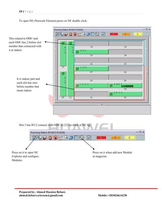
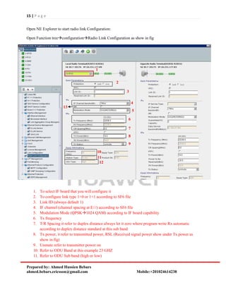
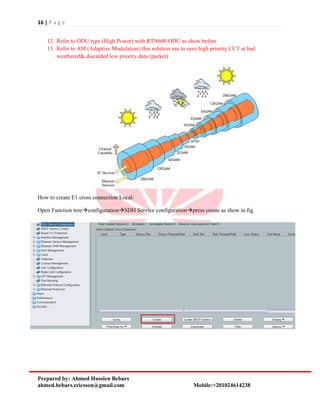
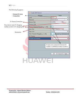
1 | P a g e
Prepared by: Ahmed Hussien Bebars
ahmed.bebars.ericsson@gmail.com Mobile:+201024614238
RTN 950
1. Outdoor:
There are two main types:
 RTN600 ODU
 RTN XMC ODU
RTN 600 ODU types:
 High Power
 Standard Power
 Low Power
Comparison between ODU:
Low power (LP) Standard Power (SP) High Power (HP)
Modulation Supported QPSK-16QAM QPSK256 QAM QPSK256 QAM
Channel Spacing 3.528 MHz 3.528 MHz 756 MHz
Min Tx power / Max
Rx Power
0 /-20 dBm -6 /-20-25 dBm 1 /-20-25 dBm
How read RAU Label at site:
MODEL:
1: refer to RAU Band 2: refer to equipment type PDH (P) or SDH (S)
3: refer to T/R (duplex distance) 4: refer to Sub band 5: refer to high power (P) & low power (N)
6: refer to output power level (standard or high)
Show ODU type
(SP or LP or HP)
Show frequency range support by this RAU
2 | P a g e
Prepared by: Ahmed Hussien Bebars
ahmed.bebars.ericsson@gmail.com Mobile:+201024614238
Table show example from Sub band and duplex distance at ODU:
ODU:
As show in figure, according to ODU direction at installation determine link Polarization (H or V), where
is no horn separated as Ericsson ODU
RTN XMC ODU
RTN 600 ODU
RTN XMC types:
XMC-1 XMC-2
Modulation Supported QPSK-16QAM QPSK256 QAM
Channel Spacing 3.528 MHz 3.556MHz
Min Tx power / Max Rx Power According to frequency According to frequency
ODU types Low capacity for PDH High power
Frequency band 723 GHz 742 GHz
3 | P a g e
Prepared by: Ahmed Hussien Bebars
ahmed.bebars.ericsson@gmail.com Mobile:+201024614238
Label:
Hybrid Coupler (Power Splitter):
There are two types:
 Balanced: losses between standard and Main equal (3dBm)
 Un Balanced: losses at stand by 6 dBm
Label:
Model:
1: indicate hybrid Coupler 2: refer to frequency band 3: refer to Balanced (B) or UN Balanced (U)
4: refer to losses at standby
Show frequency band and 2
indicate XMC-2 & 1 for
XMC-1
Show RAU sub
band Hi or low
Show frequency range
supported
4 | P a g e
Prepared by: Ahmed Hussien Bebars
ahmed.bebars.ericsson@gmail.com Mobile:+201024614238
IF cable type:
Type Applicable Distance
(Distance Between an
IDU and an ODU)
Connector IF Jumper
Required
ODU Side IDU Side
5D
cable
< 120 m Type N, male connector Type TNC, male connector No
RG-8U
cable
120 m to 180 m Type N, male connector Type N, male connector Yes
1/2-
inch
cable
180 m to 300 m Type N, male connector Type N, male connector Yes
Note: A 5D cable connects the IF interface of an ODU to the IF interface of an IDU. An RG-8U cable or 1/2-inch
cable connects the IF interface of an ODU to the IF jumper of an IDU
5 | P a g e
Prepared by: Ahmed Hussien Bebars
ahmed.bebars.ericsson@gmail.com Mobile:+201024614238
IF Specification of ODU:
Item Specification
IF Signal
Center frequency of the input IF 350 MHz
Center frequency of the RX IF 140 MHz
Return loss of the IF interface < -15 dB
ODU O&M Signal
Modulation mode ASK
Uplink signal 5.5 MHz
Downlink signal 10 MHz
Indoor:
Minimum requirements to install RTN:
1. Chassis
2. CST or CSH (main processing card)
3. IFU2 or any IF board to connect with ODU
4. FAN
5. PIU (Power interface Unit)
Chassis:
Air flow:
Heights: 2U
6 | P a g e
Prepared by: Ahmed Hussien Bebars
ahmed.bebars.ericsson@gmail.com Mobile:+201024614238
All Board installed in chassis is half slot:
Controlling Board:
CST (Control switching and timing board) CSH (Control Switching and Hybrid board)
Valid slots 7/8 main 7 & stand by 8 7/8 main 7
Service
Supported
Provide 32x32 cross connection VC4 Provide 32x32 cross connection VC4
Support VC12 (E1) & VC4 Support VC12 (E1) & VC4 & 10G Packet switching
DCN Support out band DCN Support out band and in band DCN
NMS/COM port Port RJ45 Node Management (NM) Port RJ45 Node Management (NM)
EXT To manage cascaded nodes To manage cascaded nodes
Caution: never connect EXT port and NMS port with one cable as show in fig, where two ports connected
internal on same hub
CST:
CSH:
Each card has compact flash (CF) and Dip switch to take back up from main memory like as RMM at
NPU (Ericsson vendor)
1: refer to dip switch
2: refer CF card
7 | P a g e
Prepared by: Ahmed Hussien Bebars
ahmed.bebars.ericsson@gmail.com Mobile:+201024614238
There are two buttons at card interface:
Button Name Description
CF RCV CF configuration restoration button After this button is pressed and held for eight seconds, the board
automatically restores the NE database from the CF card.
RST Warm reset button After this button is pressed, a warm reset is performed on the
board.
IF (Intermediate frequency) boards:
Main function convert baseband signal to IF (intermediate frequency)
IF1 IFU2 IFX2 ISU2 ISX2
Modulation
Supported
QPSK128
QAM
QPSK256
QAM
QPSK256
QAM
QPSK256
QAM
QPSK256
QAM
Channel spacing 728 MHZ 756 MHZ 756 MHZ 3.556 MHZ
E1 4E1STM 1 5 E175 E1 5 E175 E1 Support STM1& 2
STM1 or 5 E1 
75 E1
Support STM1& 2
STM1 or 5 E1 
75 E1
Packet rate NA 9420 Mb/S 9420 Mb/S 4456 M/bS 4456 M/bS
Min capacity 8 Mb/Sec 22 M 22 M 8 Mb/Sec 8 Mb/Sec
Max capacity 155 Mb/Sec 570 Mb/S 570 Mb/S 606 Mb/S 606 Mb/S
XPIC NA NA yes NA yes
Power -48 V -48 V -48 V -48 V -48 V
Slots (1+0)
priority
3,5,4,6,12 3,5,4,6,12 3,5,4,6,12 3,5,4,6,12 3,5,4,6,12
Slots (1+1)
Priority
3&5, 4&6, 1&2 3&5, 4&6, 1&2 3&5, 4&6, 1&2 3&5, 4&6, 1&2 3&5, 4&6, 1&2
DCN Out band only In band & Out
band
In band & Out
band
In band & Out
band
In band & Out
band
AM (Adaptive
Modulation)
NA yes yes only
in Integrated IP
radio mode
only
in Integrated IP
radio mode
IF1 Board:
IFU2:
8 | P a g e
Prepared by: Ahmed Hussien Bebars
ahmed.bebars.ericsson@gmail.com Mobile:+201024614238
IFX2:
ISU2:
ISX2:
Ethernet interface Board:
Use to drop Ethernet frame IEEE 802.3 at site
EM6T EM6TA EM6F EM6FA
FE (fast Ethernet) 4 Electrical 4 Electrical 4 Electrical 4 Electrical
GE (Giga Ethernet) 2 Electrical 2 Electrical 2 SFP (Optical) 2 SFP (Optical)
Valid Slots 4,6,2,1,3,5 4,6,2,1,3,5 4,6,2,1,3,5 4,6,2,1,3,5
9 | P a g e
Prepared by: Ahmed Hussien Bebars
ahmed.bebars.ericsson@gmail.com Mobile:+201024614238
EFP8: support Ethernet over PDH support 8 ports 10/100 Mb/Sec
Valid slots: 4, 6, 1,2,3,5
SL1D & SL1DA: use to support one STM1 or 2 STM1 channelized & two ports SFP according to SFP
type it will support electrical or Optical
SP3S & SP3D: use to support E1 dropping at site
SP3S Support 16 E1 & SP3D Support 32 E1
SP3S:
SP3D:
10 | P a g e
Prepared by: Ahmed Hussien Bebars
ahmed.bebars.ericsson@gmail.com Mobile:+201024614238
E1 cable:
E1 Panel:
Use to drop E1
physically dir RBS
PIU (Power Interface Unit):
Power cable
Input Voltage: -38.4 V to -72.0 V
FAN:
Power Consumption: 4.1 W at room temp
Power Consumption: 29 W at high temp
11 | P a g e
Prepared by: Ahmed Hussien Bebars
ahmed.bebars.ericsson@gmail.com Mobile:+201024614238
U2000 Management Server
To get current alarm at RTN node press right click on RTN node as show in fig. and choose current
alarms:
The following fig appear
Alarm with green color it mean alarm clear if color
gray it mean alarm still found
12 | P a g e
Prepared by: Ahmed Hussien Bebars
ahmed.bebars.ericsson@gmail.com Mobile:+201024614238
Main alarms and solution:
Card Alarm Meaning
CSH/CST
BD-Status & Hard Bad Card faulty & changed
RPS-IND
It mean there is switching from main to
stand by
APS-IND
indicating that the MS protection
switching occurs on SL1D card
IF1/IFU2/ISU2
IF cable Open
MW LOF Indicating that the radio frame is lost.
BD Status & Hard Bad Card faulty & changed
Volt Loss
indicating that the power voltage is
unavailable solve cold restart
MAC_EXT_EXC
indicates that the number of bit errors at
the MAC layer crosses the threshold
SL1D
TU AIS Hard Bad Cross connection not complete at path
R-LOS
indicating that the signals on the receive
line side are lost
BD status & Hard Bad Card faulty & changed
SP3D/SP3S
T-LOS
indicating that the 2 Mbit/s analog
signal is lost at the specific port
TU-AIS
There is problem at cross connection
(AIS)
UP E1 AIS E1 down from far end physical
Down E1 AIS E1 down from near end physical
BD status & Hard Bad Card faulty & changed
ODU
Radio RSL low
indicating that the radio receive power is
very low (like as RF input level)
Radio TSL low
indicating that the radio transmit power
is very low
BD status & Hard Bad Card faulty & changed
EM6F/EM6T
Eth LOS
indicating the loss of Ethernet port
connection
Eth excessive BER
Solution force speed (100 Mb/S) not
Auto negotiation
BD status & Hard Bad Card faulty & changed
13 | P a g e
Prepared by: Ahmed Hussien Bebars
ahmed.bebars.ericsson@gmail.com Mobile:+201024614238
There are two types for history alarms:
1. History alarms on NMS: this types get all alarms that synched between node at site &
U2000 server if node became down MNG & restored MNG again after specific time this
duration not synched by U2000 to get alarms at this duration use the second type
2. History alarms on NE: get all alarms on NE at site actual
to know link between two NE node and position for IF at each NE ( Site and facing) press on line
between two NE the following table appear as show in fig
This mark mean link 1+0
It mean link
from R2856
to R2853
3-IFU2 mean card IFU2 install
at slot 3 at site Source (R2856)
It mean card IFU2 install
at slot 4 at destination
(Facing)
14 | P a g e
Prepared by: Ahmed Hussien Bebars
ahmed.bebars.ericsson@gmail.com Mobile:+201024614238
To open NE (Network Element) press on NE double click:
Slot 3 has IFU2 connect with ODU at (23) as show in NE fig
It is indoor part and
each slot has zero
before number that
mean indoor
This related to ODU and
each ODU has 2 before slot
number that connected with
it at indoor
Press on it to open NE
Explorer and configure
Modules
Press on it when add new Module
at magazine
15 | P a g e
Prepared by: Ahmed Hussien Bebars
ahmed.bebars.ericsson@gmail.com Mobile:+201024614238
Open NE Explorer to start radio link Configuration:
Open Function treeconfigurationRadio Link Configuration as show in fig
1. To select IF board that you will configure it
2. To configure link type 1+0 or 1+1 according to SF6 file
3. Link ID (always default 1)
4. IF channel (channel spacing at E///) according to SF6 file
5. Modulation Mode (QPSK1024 QAM) according to IF board capability
6. Tx frequency
7. T/R Spacing it refer to duplex distance always let it zero where program write Rx automatic
according to duplex distance standard at this sub band
8. Tx power, it refer to transmitted power, RSL (Received signal power show under Tx power as
show in fig)
9. Unmute refer to transmitter power on
10. Refer to ODU Band at this example 23 GHZ
11. Refer to ODU Sub band (high or low)
1
2
3
4
5
6
7
8
9
10
11
12
13
16 | P a g e
Prepared by: Ahmed Hussien Bebars
ahmed.bebars.ericsson@gmail.com Mobile:+201024614238
12. Refer to ODU type (High Power) with RTN600 ODU as show before
13. Refer to AM (Adaptive Modulation) this solution use to save high priority CCT at bad
weathered& discarded low priority data (packet)
How to create E1 cross connection Local:
Open Function treeconfigurationSDH Service configurationpress create as show in fig
17 | P a g e
Prepared by: Ahmed Hussien Bebars
ahmed.bebars.ericsson@gmail.com Mobile:+201024614238
The following fig appears:
It mean E1 cross
Connection
E1 Source Connection
Press here to select E1 dropping
number as show in E1 dropping fig
Destination
It mean cross connection between E1
number 2 at SP3D & number 2 at IFU2
18 | P a g e
Prepared by: Ahmed Hussien Bebars
ahmed.bebars.ericsson@gmail.com Mobile:+201024614238
E1 dropping fig:
At SP3D card
The same steps with IFU2 Boarded you make cross connection at this indoor, at facing indoor received
E1 from the same E1 number that you selected here to drop it at destination card
Green slot mean available card can
make cross connection on it, Blue
Boarder mean it is selected
Select mark on needed
E1
19 | P a g e
Prepared by: Ahmed Hussien Bebars
ahmed.bebars.ericsson@gmail.com Mobile:+201024614238
To delete E1 locally (at Site):
Right click on CCT and choose Expand to Bidirectional (and start delete E1 number 2 as we created
before)
20 | P a g e
Prepared by: Ahmed Hussien Bebars
ahmed.bebars.ericsson@gmail.com Mobile:+201024614238
Native Ethernet Service types:
1. E-Line
2. E-LAN
3. QinQ
Steps to create E-LAN Service:
Open NE ExplorerConfigurationInterface ManagementEthernet Interface as show in fig
21 | P a g e
Prepared by: Ahmed Hussien Bebars
ahmed.bebars.ericsson@gmail.com Mobile:+201024614238
Configure LAN interface that will use in E-LAN Service:
Card EM6F use to support Native Ethernet LAN port and should be set this parameter at LAN Port
1. LAN Port Number
2. Port status :Enable
3. Encapsulation type: 802.1Q
4. Working Mode: Auto (auto negotiate Speed)
5. Name: description
Set Port Rule:
1. Tag aware (forward frame that has VLAN Tag and drop another tag)
2. Access (forward all frames like as no tag on frame)
3. Hybrid (forward frame with Tag or no tag)
1
2
3 4
5
22 | P a g e
Prepared by: Ahmed Hussien Bebars
ahmed.bebars.ericsson@gmail.com Mobile:+201024614238
Set parameter (Hybrid) as show in fig
Set Microwave port (at TN called WAN Port)
Open NE ExplorerConfigurationInterface ManagementMicrowave Interface
Set parameter 802.1 and write description at name part
23 | P a g e
Prepared by: Ahmed Hussien Bebars
ahmed.bebars.ericsson@gmail.com Mobile:+201024614238
Set tag type (Hybrid)
To create VLAN & assign Microwave port and EM6F port in the same VLAN (Switching)
Open NE ExplorerConfigurationEthernet Service ManagementE-LAN Service
Press here to start
switching service
24 | P a g e
Prepared by: Ahmed Hussien Bebars
ahmed.bebars.ericsson@gmail.com Mobile:+201024614238
1- Service ID: number range 1-4294967295
2- Service name: describe VLAN Name as TN
3- Press configure to start port selection
process
1- Ports that will started switching process
between them
2- VLAN ID, you can write range from VLAN
ID for ex 1-10 or write different VLAN ID
120,11,12 on the same port
1
2
3
1
2
25 | P a g e
Prepared by: Ahmed Hussien Bebars
ahmed.bebars.ericsson@gmail.com Mobile:+201024614238
RTN Management parameter:
To set RTN IP
Open NE ExplorerCommunicationCommunication Parameters
7 for all RTN
installed at VF
eg network

Rtn

  • 1.
    1 | Pa g e Prepared by: Ahmed Hussien Bebars ahmed.bebars.ericsson@gmail.com Mobile:+201024614238 RTN 950 1. Outdoor: There are two main types:  RTN600 ODU  RTN XMC ODU RTN 600 ODU types:  High Power  Standard Power  Low Power Comparison between ODU: Low power (LP) Standard Power (SP) High Power (HP) Modulation Supported QPSK-16QAM QPSK256 QAM QPSK256 QAM Channel Spacing 3.528 MHz 3.528 MHz 756 MHz Min Tx power / Max Rx Power 0 /-20 dBm -6 /-20-25 dBm 1 /-20-25 dBm How read RAU Label at site: MODEL: 1: refer to RAU Band 2: refer to equipment type PDH (P) or SDH (S) 3: refer to T/R (duplex distance) 4: refer to Sub band 5: refer to high power (P) & low power (N) 6: refer to output power level (standard or high) Show ODU type (SP or LP or HP) Show frequency range support by this RAU
  • 2.
    2 | Pa g e Prepared by: Ahmed Hussien Bebars ahmed.bebars.ericsson@gmail.com Mobile:+201024614238 Table show example from Sub band and duplex distance at ODU: ODU: As show in figure, according to ODU direction at installation determine link Polarization (H or V), where is no horn separated as Ericsson ODU RTN XMC ODU RTN 600 ODU RTN XMC types: XMC-1 XMC-2 Modulation Supported QPSK-16QAM QPSK256 QAM Channel Spacing 3.528 MHz 3.556MHz Min Tx power / Max Rx Power According to frequency According to frequency ODU types Low capacity for PDH High power Frequency band 723 GHz 742 GHz
  • 3.
    3 | Pa g e Prepared by: Ahmed Hussien Bebars ahmed.bebars.ericsson@gmail.com Mobile:+201024614238 Label: Hybrid Coupler (Power Splitter): There are two types:  Balanced: losses between standard and Main equal (3dBm)  Un Balanced: losses at stand by 6 dBm Label: Model: 1: indicate hybrid Coupler 2: refer to frequency band 3: refer to Balanced (B) or UN Balanced (U) 4: refer to losses at standby Show frequency band and 2 indicate XMC-2 & 1 for XMC-1 Show RAU sub band Hi or low Show frequency range supported
  • 4.
    4 | Pa g e Prepared by: Ahmed Hussien Bebars ahmed.bebars.ericsson@gmail.com Mobile:+201024614238 IF cable type: Type Applicable Distance (Distance Between an IDU and an ODU) Connector IF Jumper Required ODU Side IDU Side 5D cable < 120 m Type N, male connector Type TNC, male connector No RG-8U cable 120 m to 180 m Type N, male connector Type N, male connector Yes 1/2- inch cable 180 m to 300 m Type N, male connector Type N, male connector Yes Note: A 5D cable connects the IF interface of an ODU to the IF interface of an IDU. An RG-8U cable or 1/2-inch cable connects the IF interface of an ODU to the IF jumper of an IDU
  • 5.
    5 | Pa g e Prepared by: Ahmed Hussien Bebars ahmed.bebars.ericsson@gmail.com Mobile:+201024614238 IF Specification of ODU: Item Specification IF Signal Center frequency of the input IF 350 MHz Center frequency of the RX IF 140 MHz Return loss of the IF interface < -15 dB ODU O&M Signal Modulation mode ASK Uplink signal 5.5 MHz Downlink signal 10 MHz Indoor: Minimum requirements to install RTN: 1. Chassis 2. CST or CSH (main processing card) 3. IFU2 or any IF board to connect with ODU 4. FAN 5. PIU (Power interface Unit) Chassis: Air flow: Heights: 2U
  • 6.
    6 | Pa g e Prepared by: Ahmed Hussien Bebars ahmed.bebars.ericsson@gmail.com Mobile:+201024614238 All Board installed in chassis is half slot: Controlling Board: CST (Control switching and timing board) CSH (Control Switching and Hybrid board) Valid slots 7/8 main 7 & stand by 8 7/8 main 7 Service Supported Provide 32x32 cross connection VC4 Provide 32x32 cross connection VC4 Support VC12 (E1) & VC4 Support VC12 (E1) & VC4 & 10G Packet switching DCN Support out band DCN Support out band and in band DCN NMS/COM port Port RJ45 Node Management (NM) Port RJ45 Node Management (NM) EXT To manage cascaded nodes To manage cascaded nodes Caution: never connect EXT port and NMS port with one cable as show in fig, where two ports connected internal on same hub CST: CSH: Each card has compact flash (CF) and Dip switch to take back up from main memory like as RMM at NPU (Ericsson vendor) 1: refer to dip switch 2: refer CF card
  • 7.
    7 | Pa g e Prepared by: Ahmed Hussien Bebars ahmed.bebars.ericsson@gmail.com Mobile:+201024614238 There are two buttons at card interface: Button Name Description CF RCV CF configuration restoration button After this button is pressed and held for eight seconds, the board automatically restores the NE database from the CF card. RST Warm reset button After this button is pressed, a warm reset is performed on the board. IF (Intermediate frequency) boards: Main function convert baseband signal to IF (intermediate frequency) IF1 IFU2 IFX2 ISU2 ISX2 Modulation Supported QPSK128 QAM QPSK256 QAM QPSK256 QAM QPSK256 QAM QPSK256 QAM Channel spacing 728 MHZ 756 MHZ 756 MHZ 3.556 MHZ E1 4E1STM 1 5 E175 E1 5 E175 E1 Support STM1& 2 STM1 or 5 E1  75 E1 Support STM1& 2 STM1 or 5 E1  75 E1 Packet rate NA 9420 Mb/S 9420 Mb/S 4456 M/bS 4456 M/bS Min capacity 8 Mb/Sec 22 M 22 M 8 Mb/Sec 8 Mb/Sec Max capacity 155 Mb/Sec 570 Mb/S 570 Mb/S 606 Mb/S 606 Mb/S XPIC NA NA yes NA yes Power -48 V -48 V -48 V -48 V -48 V Slots (1+0) priority 3,5,4,6,12 3,5,4,6,12 3,5,4,6,12 3,5,4,6,12 3,5,4,6,12 Slots (1+1) Priority 3&5, 4&6, 1&2 3&5, 4&6, 1&2 3&5, 4&6, 1&2 3&5, 4&6, 1&2 3&5, 4&6, 1&2 DCN Out band only In band & Out band In band & Out band In band & Out band In band & Out band AM (Adaptive Modulation) NA yes yes only in Integrated IP radio mode only in Integrated IP radio mode IF1 Board: IFU2:
  • 8.
    8 | Pa g e Prepared by: Ahmed Hussien Bebars ahmed.bebars.ericsson@gmail.com Mobile:+201024614238 IFX2: ISU2: ISX2: Ethernet interface Board: Use to drop Ethernet frame IEEE 802.3 at site EM6T EM6TA EM6F EM6FA FE (fast Ethernet) 4 Electrical 4 Electrical 4 Electrical 4 Electrical GE (Giga Ethernet) 2 Electrical 2 Electrical 2 SFP (Optical) 2 SFP (Optical) Valid Slots 4,6,2,1,3,5 4,6,2,1,3,5 4,6,2,1,3,5 4,6,2,1,3,5
  • 9.
    9 | Pa g e Prepared by: Ahmed Hussien Bebars ahmed.bebars.ericsson@gmail.com Mobile:+201024614238 EFP8: support Ethernet over PDH support 8 ports 10/100 Mb/Sec Valid slots: 4, 6, 1,2,3,5 SL1D & SL1DA: use to support one STM1 or 2 STM1 channelized & two ports SFP according to SFP type it will support electrical or Optical SP3S & SP3D: use to support E1 dropping at site SP3S Support 16 E1 & SP3D Support 32 E1 SP3S: SP3D:
  • 10.
    10 | Pa g e Prepared by: Ahmed Hussien Bebars ahmed.bebars.ericsson@gmail.com Mobile:+201024614238 E1 cable: E1 Panel: Use to drop E1 physically dir RBS PIU (Power Interface Unit): Power cable Input Voltage: -38.4 V to -72.0 V FAN: Power Consumption: 4.1 W at room temp Power Consumption: 29 W at high temp
  • 11.
    11 | Pa g e Prepared by: Ahmed Hussien Bebars ahmed.bebars.ericsson@gmail.com Mobile:+201024614238 U2000 Management Server To get current alarm at RTN node press right click on RTN node as show in fig. and choose current alarms: The following fig appear Alarm with green color it mean alarm clear if color gray it mean alarm still found
  • 12.
    12 | Pa g e Prepared by: Ahmed Hussien Bebars ahmed.bebars.ericsson@gmail.com Mobile:+201024614238 Main alarms and solution: Card Alarm Meaning CSH/CST BD-Status & Hard Bad Card faulty & changed RPS-IND It mean there is switching from main to stand by APS-IND indicating that the MS protection switching occurs on SL1D card IF1/IFU2/ISU2 IF cable Open MW LOF Indicating that the radio frame is lost. BD Status & Hard Bad Card faulty & changed Volt Loss indicating that the power voltage is unavailable solve cold restart MAC_EXT_EXC indicates that the number of bit errors at the MAC layer crosses the threshold SL1D TU AIS Hard Bad Cross connection not complete at path R-LOS indicating that the signals on the receive line side are lost BD status & Hard Bad Card faulty & changed SP3D/SP3S T-LOS indicating that the 2 Mbit/s analog signal is lost at the specific port TU-AIS There is problem at cross connection (AIS) UP E1 AIS E1 down from far end physical Down E1 AIS E1 down from near end physical BD status & Hard Bad Card faulty & changed ODU Radio RSL low indicating that the radio receive power is very low (like as RF input level) Radio TSL low indicating that the radio transmit power is very low BD status & Hard Bad Card faulty & changed EM6F/EM6T Eth LOS indicating the loss of Ethernet port connection Eth excessive BER Solution force speed (100 Mb/S) not Auto negotiation BD status & Hard Bad Card faulty & changed
  • 13.
    13 | Pa g e Prepared by: Ahmed Hussien Bebars ahmed.bebars.ericsson@gmail.com Mobile:+201024614238 There are two types for history alarms: 1. History alarms on NMS: this types get all alarms that synched between node at site & U2000 server if node became down MNG & restored MNG again after specific time this duration not synched by U2000 to get alarms at this duration use the second type 2. History alarms on NE: get all alarms on NE at site actual to know link between two NE node and position for IF at each NE ( Site and facing) press on line between two NE the following table appear as show in fig This mark mean link 1+0 It mean link from R2856 to R2853 3-IFU2 mean card IFU2 install at slot 3 at site Source (R2856) It mean card IFU2 install at slot 4 at destination (Facing)
  • 14.
    14 | Pa g e Prepared by: Ahmed Hussien Bebars ahmed.bebars.ericsson@gmail.com Mobile:+201024614238 To open NE (Network Element) press on NE double click: Slot 3 has IFU2 connect with ODU at (23) as show in NE fig It is indoor part and each slot has zero before number that mean indoor This related to ODU and each ODU has 2 before slot number that connected with it at indoor Press on it to open NE Explorer and configure Modules Press on it when add new Module at magazine
  • 15.
    15 | Pa g e Prepared by: Ahmed Hussien Bebars ahmed.bebars.ericsson@gmail.com Mobile:+201024614238 Open NE Explorer to start radio link Configuration: Open Function treeconfigurationRadio Link Configuration as show in fig 1. To select IF board that you will configure it 2. To configure link type 1+0 or 1+1 according to SF6 file 3. Link ID (always default 1) 4. IF channel (channel spacing at E///) according to SF6 file 5. Modulation Mode (QPSK1024 QAM) according to IF board capability 6. Tx frequency 7. T/R Spacing it refer to duplex distance always let it zero where program write Rx automatic according to duplex distance standard at this sub band 8. Tx power, it refer to transmitted power, RSL (Received signal power show under Tx power as show in fig) 9. Unmute refer to transmitter power on 10. Refer to ODU Band at this example 23 GHZ 11. Refer to ODU Sub band (high or low) 1 2 3 4 5 6 7 8 9 10 11 12 13
  • 16.
    16 | Pa g e Prepared by: Ahmed Hussien Bebars ahmed.bebars.ericsson@gmail.com Mobile:+201024614238 12. Refer to ODU type (High Power) with RTN600 ODU as show before 13. Refer to AM (Adaptive Modulation) this solution use to save high priority CCT at bad weathered& discarded low priority data (packet) How to create E1 cross connection Local: Open Function treeconfigurationSDH Service configurationpress create as show in fig
  • 17.
    17 | Pa g e Prepared by: Ahmed Hussien Bebars ahmed.bebars.ericsson@gmail.com Mobile:+201024614238 The following fig appears: It mean E1 cross Connection E1 Source Connection Press here to select E1 dropping number as show in E1 dropping fig Destination It mean cross connection between E1 number 2 at SP3D & number 2 at IFU2
  • 18.
    18 | Pa g e Prepared by: Ahmed Hussien Bebars ahmed.bebars.ericsson@gmail.com Mobile:+201024614238 E1 dropping fig: At SP3D card The same steps with IFU2 Boarded you make cross connection at this indoor, at facing indoor received E1 from the same E1 number that you selected here to drop it at destination card Green slot mean available card can make cross connection on it, Blue Boarder mean it is selected Select mark on needed E1
  • 19.
    19 | Pa g e Prepared by: Ahmed Hussien Bebars ahmed.bebars.ericsson@gmail.com Mobile:+201024614238 To delete E1 locally (at Site): Right click on CCT and choose Expand to Bidirectional (and start delete E1 number 2 as we created before)
  • 20.
    20 | Pa g e Prepared by: Ahmed Hussien Bebars ahmed.bebars.ericsson@gmail.com Mobile:+201024614238 Native Ethernet Service types: 1. E-Line 2. E-LAN 3. QinQ Steps to create E-LAN Service: Open NE ExplorerConfigurationInterface ManagementEthernet Interface as show in fig
  • 21.
    21 | Pa g e Prepared by: Ahmed Hussien Bebars ahmed.bebars.ericsson@gmail.com Mobile:+201024614238 Configure LAN interface that will use in E-LAN Service: Card EM6F use to support Native Ethernet LAN port and should be set this parameter at LAN Port 1. LAN Port Number 2. Port status :Enable 3. Encapsulation type: 802.1Q 4. Working Mode: Auto (auto negotiate Speed) 5. Name: description Set Port Rule: 1. Tag aware (forward frame that has VLAN Tag and drop another tag) 2. Access (forward all frames like as no tag on frame) 3. Hybrid (forward frame with Tag or no tag) 1 2 3 4 5
  • 22.
    22 | Pa g e Prepared by: Ahmed Hussien Bebars ahmed.bebars.ericsson@gmail.com Mobile:+201024614238 Set parameter (Hybrid) as show in fig Set Microwave port (at TN called WAN Port) Open NE ExplorerConfigurationInterface ManagementMicrowave Interface Set parameter 802.1 and write description at name part
  • 23.
    23 | Pa g e Prepared by: Ahmed Hussien Bebars ahmed.bebars.ericsson@gmail.com Mobile:+201024614238 Set tag type (Hybrid) To create VLAN & assign Microwave port and EM6F port in the same VLAN (Switching) Open NE ExplorerConfigurationEthernet Service ManagementE-LAN Service Press here to start switching service
  • 24.
    24 | Pa g e Prepared by: Ahmed Hussien Bebars ahmed.bebars.ericsson@gmail.com Mobile:+201024614238 1- Service ID: number range 1-4294967295 2- Service name: describe VLAN Name as TN 3- Press configure to start port selection process 1- Ports that will started switching process between them 2- VLAN ID, you can write range from VLAN ID for ex 1-10 or write different VLAN ID 120,11,12 on the same port 1 2 3 1 2
  • 25.
    25 | Pa g e Prepared by: Ahmed Hussien Bebars ahmed.bebars.ericsson@gmail.com Mobile:+201024614238 RTN Management parameter: To set RTN IP Open NE ExplorerCommunicationCommunication Parameters 7 for all RTN installed at VF eg network