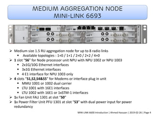
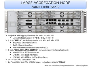
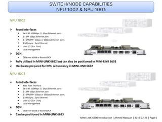
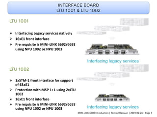
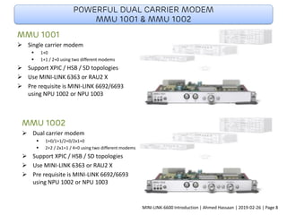
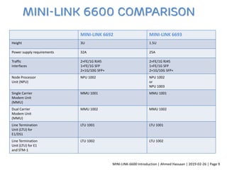
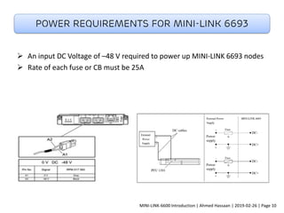
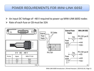
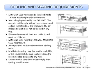
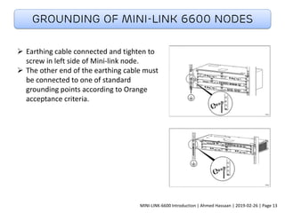
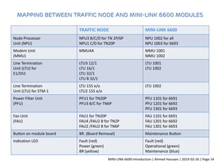
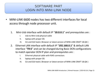
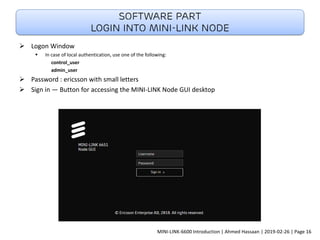
Transport Network evolution
MINI-LINK 6600 nodes
F u t u r e p r o o f w i t h b a c k wa r d c o m pat i b i l i t y
MINI-LINK-6600 Introduction | Ahmed Hassaan | 2019-02-26 | Page 1
MINI-LINK-6600 Introduction | Ahmed Hassaan | 2019-02-26 | Page 2
MINI-LINK-6600 Introduction | Ahmed Hassaan | 2019-02-26 | Page 3
Medium Aggregation Node
MINI-LINK 6693
➢ Medium size 1.5 RU aggregation node for up to 8 radio links
▪ Available topologies : 1+0 / 1+1 / 2+0 / 2+2 / 4+0
➢ 1 slot “S6” for Node processor unit NPU with NPU 1002 or NPU 1003
▪ 2x1G/10G Ethernet interfaces
▪ 3x1G Ethernet interfaces
▪ 4 E1 interface for NPU 1003 only
➢ 4 slots “S1,S2,S4&S5” for Modems or interface plug in unit
▪ MMU 1001 or 1002 dual carrier
▪ LTU 1001 with 16E1 interfaces
▪ LTU 1002 with 16E1 or 1xSTM-1 interfaces
➢ 1x Fan Unit FAU 1301 at slot “S0”
➢ 1x Power Filter Unit PFU 1301 at slot “S3” with dual power input for power
redundancy
MINI-LINK-6600 Introduction | Ahmed Hassaan | 2019-02-26 | Page 4
Large aggregation node
MINI-LINK 6692
➢ Large size 3 RU aggregation node for up to 16 radio links
▪ Available topologies : 1+0 / 1+1 / 2+0 / 2+2 / 4+0
➢ 2 slots “S9&S10” for Node processor unit NPU with NPU 1002
▪ 2x1G/10G Ethernet interfaces
▪ 3x1G Ethernet interfaces
▪ NPU redundancy with additional NPU 1002
➢ 8 slots “S1,S2,S5,S6,S7,S8,S11&S12” for Modems or interface plug in unit
▪ MMU 1001 or 1002 dual carrier
▪ LTU 1001 with 16E1 interfaces
▪ LTU 1002 with 16E1 or 1xSTM-1 interfaces
➢ 1x Fan Unit FAU 1201 at slot “S0”
➢ 2x Power Filter Unit PFU 1201 for power redundancy at slots “S3&S4”
MINI-LINK-6600 Introduction | Ahmed Hassaan | 2019-02-26 | Page 5
Switch/node capabilities
NPU 1002 & NPU 1003
NPU 1002
➢ Front Interfaces
▪ 2x RJ 45 100Mbps / 1 Gbps Ethernet ports
▪ 1 x SFP 1Gbps Ethernet port
▪ 2 x SFP/SFP+ 1Gbps or 10Gbps Ethernet ports
▪ 2 MHz sync , Sync Ethernet
▪ User I/O (3 in 3 out)
▪ Local management
➢ DCN
▪ DCN over VLAN or Routed DCN
➢ Fully utilized in MINI-LINK 6692 but can also be positioned in MINI-LINK 6693
➢ Hardware prepared for NPU redundancy in MINI-LINK 6692
NPU 1003
➢ Front Interfaces
▪ 4xE1 front interface
▪ 2x RJ 45 100Mbps / 1 Gbps Ethernet ports
▪ 1 x SFP 1Gbps Ethernet port
▪ 2 x SFP/SFP+ 1Gbps or 10Gbps Ethernet ports
▪ 2 MHz sync , Sync Ethernet
▪ User I/O (2 in 1 out)
▪ Local management
➢ DCN
▪ DCN over VLAN or Routed DCN
➢ Can be positioned in MINI-LINK 6693
MINI-LINK-6600 Introduction | Ahmed Hassaan | 2019-02-26 | Page 6
Interface board
LTU 1001 & LTU 1002
LTU 1001
➢ Interfacing Legacy services natively
➢ 16xE1 front interface
➢ Pre requisite is MINI-LINK 6692/6693
using NPU 1002 or NPU 1003
LTU 1002
➢ 1xSTM-1 front interface for support
of 63xE1
➢ Protection with MSP 1+1 using 2xLTU
1002
➢ 16xE1 front interface
➢ Pre requisite is MINI-LINK 6692/6693
using NPU 1002 or NPU 1003
MINI-LINK-6600 Introduction | Ahmed Hassaan | 2019-02-26 | Page 7
Powerful dual carrier modem
MMU 1001 & MMU 1002
MMU 1001
➢ Single carrier modem
▪ 1+0
▪ 1+1 / 2+0 using two different modems
➢ Support XPIC / HSB / SD topologies
➢ Use MINI-LINK 6363 or RAU2 X
➢ Pre requisite is MINI-LINK 6692/6693
using NPU 1002 or NPU 1003
MMU 1002
➢ Dual carrier modem
▪ 1+0/1+1/2+0/2x1+0
▪ 2+2 / 2x1+1 / 4+0 using two different modems
➢ Support XPIC / HSB / SD topologies
➢ Use MINI-LINK 6363 or RAU2 X
➢ Pre requisite is MINI-LINK 6692/6693
using NPU 1002 or NPU 1003
MINI-LINK-6600 Introduction | Ahmed Hassaan | 2019-02-26 | Page 8
MINI-LINK 6692 MINI-LINK 6693
Height 3U 1.5U
Power supply requirements 32A 25A
Traffic
interfaces
2×FE/1G RJ45
1×FE/1G SFP
2×1G/10G SFP+
2×FE/1G RJ45
1×FE/1G SFP
2×1G/10G SFP+
Node Processor
Unit (NPU)
NPU 1002 NPU 1002
or
NPU 1003
Single Carrier
Modem Unit
(MMU)
MMU 1001 MMU 1001
Dual Carrier
Modem Unit
(MMU)
MMU 1002 MMU 1002
Line Termination
Unit (LTU) for
E1/DS1
LTU 1001 LTU 1001
Line Termination
Unit (LTU) for E1
and STM-1
LTU 1002 LTU 1002
MINI-LINK 6600 Comparison
MINI-LINK-6600 Introduction | Ahmed Hassaan | 2019-02-26 | Page 9
➢ An input DC Voltage of –48 V required to power up MINI-LINK 6693 nodes
➢ Rate of each fuse or CB must be 25A
Power requirements for MINI-LINK 6693
MINI-LINK-6600 Introduction | Ahmed Hassaan | 2019-02-26 | Page 10
➢ An input DC Voltage of –48 V required to power up MINI-LINK 6692 nodes
➢ Rate of each fuse or CB must be 32A
Power requirements for MINI-LINK 6692
MINI-LINK-6600 Introduction | Ahmed Hassaan | 2019-02-26 | Page 11
Cooling and Spacing requirements
➢ MINI-LINK 6600 nodes can be installed inside
19” rack according to their dimensions
➢ Air-cooling is provided by the FAN UNIT . The
air enters at the right side of the enclosure and
exits at the left side of the enclosure. The air
inlet and outlet must not be blocked in any
way.
➢ Distance between air inlet and outlet to wall
must be ≥ 20 mm.
➢ MINI-LINK 6693 height is 1.5U while MINI-LINK
6692 height is 3U.
➢ All empty slots must be covered with dummy
units.
➢ Insufficient cooling may shorten the useful life
of the equipment. Be sure to always keep the
recommended distance to any wall.
➢ Environmental conditions must comply with
cooling specifications.
MINI-LINK-6600 Introduction | Ahmed Hassaan | 2019-02-26 | Page 12
Grounding of MINI-LINK 6600 NODES
➢ Earthing cable connected and tighten to
screw in left side of Mini-link node.
➢ The other end of the earthing cable must
be connected to one of standard
grounding points according to Orange
acceptance criteria.
MINI-LINK-6600 Introduction | Ahmed Hassaan | 2019-02-26 | Page 13
Mapping between Traffic Node and MINI-LINK 6600 modules
TRAFFIC NODE MINI-LINK 6600
Node Processor
Unit (NPU)
NPU3 B/C/D for TN 2P/6P
NPU1 C/D for TN20P
NPU 1002 for all
NPU 1003 for 6693
Modem Unit
(MMU)
MMU4A MMU 1001
MMU 1002
Line Termination
Unit (LTU) for
E1/DS1
LTU3 12/1
LTU 16/1
LTU 32/1
LTU B 32/1
LTU 1001
LTU 1002
Line Termination
Unit (LTU) for STM-1
LTU 155 e/o
LTU2 155 e/o
LTU 1002
Power Filter Unit
(PFU)
PFU1 for TN20P
PFU3 B/C for TN6P
PFU 1101 for 6691
PFU 1201 for 6692
PFU 1301 for 6693
Fan Unit
(FAU)
FAU1 for TN20P
FAU4 /FAU2 B for TN2P
FAU2 /FAU2 B for TN6P
FAU 1101 for 6691
FAU 1201 for 6692
FAU 1301 for 6693
Button on module board BR. (Board Removal) Maintenance Button
Indication LED Fault (red)
Power (green)
BR (yellow)
Fault (red)
Operational (green)
Maintenance (blue)
MINI-LINK-6600 Introduction | Ahmed Hassaan | 2019-02-26 | Page 14
• MINI-LINK 6600 nodes has two different interfaces for local
access through node processor unit.
1. Mini-Usb interface with default IP “10.0.0.1” and prerequisites are :
I. Usb to Mini-Usb physical cable
II. laptop with proper OS
III. CLI and GUI tools ( Browser or latest version of MINI-LINK CRAFT 18.Q4 )
2. Ethernet LAN interface with default IP “192.168.0.1” & default LAN
interface “TR:5” and can be changed during Basic DCN configurations
to match operator DCN IP plan and prerequisites are :
I. Ethernet physical cable with RJ45 connectors
II. laptop with proper OS
III. CLI and GUI tools ( Browser or latest version of MINI-LINK CRAFT 18.Q4 )
Software part
Login into Mini-link node
MINI-LINK-6600 Introduction | Ahmed Hassaan | 2019-02-26 | Page 15
➢ Logon Window
▪ In case of local authentication, use one of the following:
control_user
admin_user
➢ Password : ericsson with small letters
➢ Sign in — Button for accessing the MINI-LINK Node GUI desktop
Software part
Login into Mini-link node
MINI-LINK-6600 Introduction | Ahmed Hassaan | 2019-02-26 | Page 16
User Interface Overview
A : Management tree — Shows the
tree of managed objects
B : Main area — Contains the main
area for working with the NE.
C : Notification list — Displays alarm
notifications
D : Title bar — Contains the current
page title and buttons for commonly
used tasks.
E : Licenses counter — Displays the
total number of license notifications
in the NE
F : Alarms counter — Displays the
total number of active alarms in the
NE
G : User settings menu — Contains
general user settings and the Log Out
button
Software part
Login into Mini-link node
MINI-LINK-6600 Introduction | Ahmed Hassaan | 2019-02-26 | Page 17
Software part
Radio link configurations
MINI-LINK-6600 Introduction | Ahmed Hassaan | 2019-02-26 | Page 18
Software part
Radio link configurations
MINI-LINK-6600 Introduction | Ahmed Hassaan | 2019-02-26 | Page 19
Software part
RSL window
MINI-LINK-6600 Introduction | Ahmed Hassaan | 2019-02-26 | Page 20
Software part
RSL window
MINI-LINK-6600 Introduction | Ahmed Hassaan | 2019-02-26 | Page 21
Software part
Link performance
MINI-LINK-6600 Introduction | Ahmed Hassaan | 2019-02-26 | Page 22
Software part
DCN configurations ( Basic NE )
MINI-LINK-6600 Introduction | Ahmed Hassaan | 2019-02-26 | Page 23
Software part
DCN configurations ( ospf area )
MINI-LINK-6600 Introduction | Ahmed Hassaan | 2019-02-26 | Page 24
Software part
Supervision ping test via cli tool
➢ We have three different cli windows
1. CLI window opened in MINI-LINK CRAFT window
2. Cmd window in START menu in windows OS
3. PuTTY CLI tool and it is recommended
MINI-LINK-6600 Introduction | Ahmed Hassaan | 2019-02-26 | Page 25
Software part
Node alarms
MINI-LINK-6600 Introduction | Ahmed Hassaan | 2019-02-26 | Page 26
Software part
TDM E1 loop test
MINI-LINK-6600 Introduction | Ahmed Hassaan | 2019-02-26 | Page 27
Ericsson Mini-link 6600 Nodes

Ericsson Mini-link 6600 Nodes

  • 1.
  • 2.
    F u tu r e p r o o f w i t h b a c k wa r d c o m pat i b i l i t y MINI-LINK-6600 Introduction | Ahmed Hassaan | 2019-02-26 | Page 1
  • 3.
    MINI-LINK-6600 Introduction |Ahmed Hassaan | 2019-02-26 | Page 2
  • 4.
    MINI-LINK-6600 Introduction |Ahmed Hassaan | 2019-02-26 | Page 3
  • 5.
    Medium Aggregation Node MINI-LINK6693 ➢ Medium size 1.5 RU aggregation node for up to 8 radio links ▪ Available topologies : 1+0 / 1+1 / 2+0 / 2+2 / 4+0 ➢ 1 slot “S6” for Node processor unit NPU with NPU 1002 or NPU 1003 ▪ 2x1G/10G Ethernet interfaces ▪ 3x1G Ethernet interfaces ▪ 4 E1 interface for NPU 1003 only ➢ 4 slots “S1,S2,S4&S5” for Modems or interface plug in unit ▪ MMU 1001 or 1002 dual carrier ▪ LTU 1001 with 16E1 interfaces ▪ LTU 1002 with 16E1 or 1xSTM-1 interfaces ➢ 1x Fan Unit FAU 1301 at slot “S0” ➢ 1x Power Filter Unit PFU 1301 at slot “S3” with dual power input for power redundancy MINI-LINK-6600 Introduction | Ahmed Hassaan | 2019-02-26 | Page 4
  • 6.
    Large aggregation node MINI-LINK6692 ➢ Large size 3 RU aggregation node for up to 16 radio links ▪ Available topologies : 1+0 / 1+1 / 2+0 / 2+2 / 4+0 ➢ 2 slots “S9&S10” for Node processor unit NPU with NPU 1002 ▪ 2x1G/10G Ethernet interfaces ▪ 3x1G Ethernet interfaces ▪ NPU redundancy with additional NPU 1002 ➢ 8 slots “S1,S2,S5,S6,S7,S8,S11&S12” for Modems or interface plug in unit ▪ MMU 1001 or 1002 dual carrier ▪ LTU 1001 with 16E1 interfaces ▪ LTU 1002 with 16E1 or 1xSTM-1 interfaces ➢ 1x Fan Unit FAU 1201 at slot “S0” ➢ 2x Power Filter Unit PFU 1201 for power redundancy at slots “S3&S4” MINI-LINK-6600 Introduction | Ahmed Hassaan | 2019-02-26 | Page 5
  • 7.
    Switch/node capabilities NPU 1002& NPU 1003 NPU 1002 ➢ Front Interfaces ▪ 2x RJ 45 100Mbps / 1 Gbps Ethernet ports ▪ 1 x SFP 1Gbps Ethernet port ▪ 2 x SFP/SFP+ 1Gbps or 10Gbps Ethernet ports ▪ 2 MHz sync , Sync Ethernet ▪ User I/O (3 in 3 out) ▪ Local management ➢ DCN ▪ DCN over VLAN or Routed DCN ➢ Fully utilized in MINI-LINK 6692 but can also be positioned in MINI-LINK 6693 ➢ Hardware prepared for NPU redundancy in MINI-LINK 6692 NPU 1003 ➢ Front Interfaces ▪ 4xE1 front interface ▪ 2x RJ 45 100Mbps / 1 Gbps Ethernet ports ▪ 1 x SFP 1Gbps Ethernet port ▪ 2 x SFP/SFP+ 1Gbps or 10Gbps Ethernet ports ▪ 2 MHz sync , Sync Ethernet ▪ User I/O (2 in 1 out) ▪ Local management ➢ DCN ▪ DCN over VLAN or Routed DCN ➢ Can be positioned in MINI-LINK 6693 MINI-LINK-6600 Introduction | Ahmed Hassaan | 2019-02-26 | Page 6
  • 8.
    Interface board LTU 1001& LTU 1002 LTU 1001 ➢ Interfacing Legacy services natively ➢ 16xE1 front interface ➢ Pre requisite is MINI-LINK 6692/6693 using NPU 1002 or NPU 1003 LTU 1002 ➢ 1xSTM-1 front interface for support of 63xE1 ➢ Protection with MSP 1+1 using 2xLTU 1002 ➢ 16xE1 front interface ➢ Pre requisite is MINI-LINK 6692/6693 using NPU 1002 or NPU 1003 MINI-LINK-6600 Introduction | Ahmed Hassaan | 2019-02-26 | Page 7
  • 9.
    Powerful dual carriermodem MMU 1001 & MMU 1002 MMU 1001 ➢ Single carrier modem ▪ 1+0 ▪ 1+1 / 2+0 using two different modems ➢ Support XPIC / HSB / SD topologies ➢ Use MINI-LINK 6363 or RAU2 X ➢ Pre requisite is MINI-LINK 6692/6693 using NPU 1002 or NPU 1003 MMU 1002 ➢ Dual carrier modem ▪ 1+0/1+1/2+0/2x1+0 ▪ 2+2 / 2x1+1 / 4+0 using two different modems ➢ Support XPIC / HSB / SD topologies ➢ Use MINI-LINK 6363 or RAU2 X ➢ Pre requisite is MINI-LINK 6692/6693 using NPU 1002 or NPU 1003 MINI-LINK-6600 Introduction | Ahmed Hassaan | 2019-02-26 | Page 8
  • 10.
    MINI-LINK 6692 MINI-LINK6693 Height 3U 1.5U Power supply requirements 32A 25A Traffic interfaces 2×FE/1G RJ45 1×FE/1G SFP 2×1G/10G SFP+ 2×FE/1G RJ45 1×FE/1G SFP 2×1G/10G SFP+ Node Processor Unit (NPU) NPU 1002 NPU 1002 or NPU 1003 Single Carrier Modem Unit (MMU) MMU 1001 MMU 1001 Dual Carrier Modem Unit (MMU) MMU 1002 MMU 1002 Line Termination Unit (LTU) for E1/DS1 LTU 1001 LTU 1001 Line Termination Unit (LTU) for E1 and STM-1 LTU 1002 LTU 1002 MINI-LINK 6600 Comparison MINI-LINK-6600 Introduction | Ahmed Hassaan | 2019-02-26 | Page 9
  • 11.
    ➢ An inputDC Voltage of –48 V required to power up MINI-LINK 6693 nodes ➢ Rate of each fuse or CB must be 25A Power requirements for MINI-LINK 6693 MINI-LINK-6600 Introduction | Ahmed Hassaan | 2019-02-26 | Page 10
  • 12.
    ➢ An inputDC Voltage of –48 V required to power up MINI-LINK 6692 nodes ➢ Rate of each fuse or CB must be 32A Power requirements for MINI-LINK 6692 MINI-LINK-6600 Introduction | Ahmed Hassaan | 2019-02-26 | Page 11
  • 13.
    Cooling and Spacingrequirements ➢ MINI-LINK 6600 nodes can be installed inside 19” rack according to their dimensions ➢ Air-cooling is provided by the FAN UNIT . The air enters at the right side of the enclosure and exits at the left side of the enclosure. The air inlet and outlet must not be blocked in any way. ➢ Distance between air inlet and outlet to wall must be ≥ 20 mm. ➢ MINI-LINK 6693 height is 1.5U while MINI-LINK 6692 height is 3U. ➢ All empty slots must be covered with dummy units. ➢ Insufficient cooling may shorten the useful life of the equipment. Be sure to always keep the recommended distance to any wall. ➢ Environmental conditions must comply with cooling specifications. MINI-LINK-6600 Introduction | Ahmed Hassaan | 2019-02-26 | Page 12
  • 14.
    Grounding of MINI-LINK6600 NODES ➢ Earthing cable connected and tighten to screw in left side of Mini-link node. ➢ The other end of the earthing cable must be connected to one of standard grounding points according to Orange acceptance criteria. MINI-LINK-6600 Introduction | Ahmed Hassaan | 2019-02-26 | Page 13
  • 15.
    Mapping between TrafficNode and MINI-LINK 6600 modules TRAFFIC NODE MINI-LINK 6600 Node Processor Unit (NPU) NPU3 B/C/D for TN 2P/6P NPU1 C/D for TN20P NPU 1002 for all NPU 1003 for 6693 Modem Unit (MMU) MMU4A MMU 1001 MMU 1002 Line Termination Unit (LTU) for E1/DS1 LTU3 12/1 LTU 16/1 LTU 32/1 LTU B 32/1 LTU 1001 LTU 1002 Line Termination Unit (LTU) for STM-1 LTU 155 e/o LTU2 155 e/o LTU 1002 Power Filter Unit (PFU) PFU1 for TN20P PFU3 B/C for TN6P PFU 1101 for 6691 PFU 1201 for 6692 PFU 1301 for 6693 Fan Unit (FAU) FAU1 for TN20P FAU4 /FAU2 B for TN2P FAU2 /FAU2 B for TN6P FAU 1101 for 6691 FAU 1201 for 6692 FAU 1301 for 6693 Button on module board BR. (Board Removal) Maintenance Button Indication LED Fault (red) Power (green) BR (yellow) Fault (red) Operational (green) Maintenance (blue) MINI-LINK-6600 Introduction | Ahmed Hassaan | 2019-02-26 | Page 14
  • 16.
    • MINI-LINK 6600nodes has two different interfaces for local access through node processor unit. 1. Mini-Usb interface with default IP “10.0.0.1” and prerequisites are : I. Usb to Mini-Usb physical cable II. laptop with proper OS III. CLI and GUI tools ( Browser or latest version of MINI-LINK CRAFT 18.Q4 ) 2. Ethernet LAN interface with default IP “192.168.0.1” & default LAN interface “TR:5” and can be changed during Basic DCN configurations to match operator DCN IP plan and prerequisites are : I. Ethernet physical cable with RJ45 connectors II. laptop with proper OS III. CLI and GUI tools ( Browser or latest version of MINI-LINK CRAFT 18.Q4 ) Software part Login into Mini-link node MINI-LINK-6600 Introduction | Ahmed Hassaan | 2019-02-26 | Page 15
  • 17.
    ➢ Logon Window ▪In case of local authentication, use one of the following: control_user admin_user ➢ Password : ericsson with small letters ➢ Sign in — Button for accessing the MINI-LINK Node GUI desktop Software part Login into Mini-link node MINI-LINK-6600 Introduction | Ahmed Hassaan | 2019-02-26 | Page 16
  • 18.
    User Interface Overview A: Management tree — Shows the tree of managed objects B : Main area — Contains the main area for working with the NE. C : Notification list — Displays alarm notifications D : Title bar — Contains the current page title and buttons for commonly used tasks. E : Licenses counter — Displays the total number of license notifications in the NE F : Alarms counter — Displays the total number of active alarms in the NE G : User settings menu — Contains general user settings and the Log Out button Software part Login into Mini-link node MINI-LINK-6600 Introduction | Ahmed Hassaan | 2019-02-26 | Page 17
  • 19.
    Software part Radio linkconfigurations MINI-LINK-6600 Introduction | Ahmed Hassaan | 2019-02-26 | Page 18
  • 20.
    Software part Radio linkconfigurations MINI-LINK-6600 Introduction | Ahmed Hassaan | 2019-02-26 | Page 19
  • 21.
    Software part RSL window MINI-LINK-6600Introduction | Ahmed Hassaan | 2019-02-26 | Page 20
  • 22.
    Software part RSL window MINI-LINK-6600Introduction | Ahmed Hassaan | 2019-02-26 | Page 21
  • 23.
    Software part Link performance MINI-LINK-6600Introduction | Ahmed Hassaan | 2019-02-26 | Page 22
  • 24.
    Software part DCN configurations( Basic NE ) MINI-LINK-6600 Introduction | Ahmed Hassaan | 2019-02-26 | Page 23
  • 25.
    Software part DCN configurations( ospf area ) MINI-LINK-6600 Introduction | Ahmed Hassaan | 2019-02-26 | Page 24
  • 26.
    Software part Supervision pingtest via cli tool ➢ We have three different cli windows 1. CLI window opened in MINI-LINK CRAFT window 2. Cmd window in START menu in windows OS 3. PuTTY CLI tool and it is recommended MINI-LINK-6600 Introduction | Ahmed Hassaan | 2019-02-26 | Page 25
  • 27.
    Software part Node alarms MINI-LINK-6600Introduction | Ahmed Hassaan | 2019-02-26 | Page 26
  • 28.
    Software part TDM E1loop test MINI-LINK-6600 Introduction | Ahmed Hassaan | 2019-02-26 | Page 27